SlideShare a Scribd company logo
1 of 27
Download to read offline
Chapter 9
Shaping Machines
9.1 Introduction
The shaper is a machine tool having a reciprocating cutting tool of the lathe type, which
takes a straight line cut. It is primarily intended to produce flat surfaces. These surfaces
may be horizontal, vertical or inclined. The main significance of this machine lies in its
greater flexibilityon account of ease in work holding, quick adjustment and use of tools of
relatively simple design. In the light of above fact it is almost an indispensable machine in
tool rooms die making shops and general repair shops for the production of a few identical
shapes of jobs. It can also be adopted for producing curved and irregular surfaces.
9.2 Working Principle
The working principle of a shaper is illustrated in the Fig.9.1.
Fig.9.1. Working Principle of a Shaper
On a shaper the job is usually fixed in a vice on the machine table. The tool is held in the
tool post, mounted on the ram of the machine. As the ram reciprocates to and for the cutting
tool cuts the material in forward stroke only except in case of
9.2
draw cuts shaper, in which the tool cuts in backward stroke of the ram. The other stroke in
both the cases remains idle, as there is no cutting action in this stroke and hence termed as
idle strokes.
9.3 Types of Shapers
Shapers are classified in a number of ways depending upon the general features of design or
the purpose for which they are intended. Shapers are classified under the following
headings.
1) According to the type of mechanism used for giving reciprocating motion to
the ram
(a) Crank type (b) Geared type (c) Hydraulic type
2) According to the position and travel of ram
(a) Horizontal type (b) Vertical type (c) Traveling head type
3) According to the type of design of the table:
(a) Standard shaper (b) universal shaper
4) According to the type of cutting stroke
(a) Push type (b) Draw type
9.3.1 Crank Shaper
This is the most common type of shaper in which a single point cutting tool is given' a
reciprocating motion equal to the length of the stroke desired while the work is clamped in
position on an adjustable table. In construction, the crank shaper employs a crank
mechanism to change circular motion of a large gear called "bull gear" incorporated in the
machine to reciprocating motion of the ram. The bull gear receives power either from an
individual motor or from an overhead line shaft if it is a belt driven shaper.
9.3.2 Geared type
The reciprocating motion of the ram in some type of shaper is effected by means of a rack
and pinion. The rack teeth, which are cut directly below the ram, mesh with a spur gear.
The pinion meshing with the rack is driven by a gear train. The speed and the direction in
which the machine will traverse depend on the number of gears in the gear train. This type
of shaper is not very widely used.
9.3.3 Hydraulic Shaper
In a hydraulic shaper reciprocating movement of the ram is obtained by hydraulic power.
Oil under high pressure is pumped in to the operating cylinder fitted with a piston. The end
of the piston rod is connected to the ram. The high-pressure oil first acts on one side of the
piston and then on the other causing the piston to reciprocate and the motion is transmitted
to the ram. The piston speed is changed by varying the amount of liquid delivered by the
pump. One of the most important advantages of this type of shaper is that the cutting speed
and force of the ram drive are constant
Shaping Machines 9.3
from the very beginning to the end of the cut. It also offers great flexibility up of motion
when the cutting tool is overloaded. Protecting the parts or the tools from breakage. Another
advantages is that the machine does not make any noise and operates very quietly.
9.3.4 Horizontal Shaper
In a horizontal shaper, the ram holding the tool reciprocates in a horizontal axis. Horizontal
shapers are mainly used to produce flat surfaces.
9.3.5 Vertical Shaper
In a vertical shaper, the ram holding the tool reciprocates in a vertical axis. In some of the
vertical machines provision is made to allow adjustment of the ram to an angle of about 10
degrees from the vertical position. Vertical shapers may be crank driven, rack driven, screw
driven or hydraulic power driven. The work table of a vertical shaper can be given cross,
longitudinal, and rotary movement. The tool used on a vertical shaper is entirely different
from that used on a horizontal shaper. Vertical shapers are very convenient for machining
internal surfaces, keyways, slots or grooves; large internal and external gears may also be
machined by indexing arrangement of the rotary table. There are vertical shapers, which are
specially designed for machining internal keyways. They are then called keyseaters.
9.3.6 Travelling Head Shaper
In a travelling head shaper, the ram carrying the tool while it reciprocates moves
crosswise to give the required feed. Heavy and unwiedly jobs, which are very difficult to
hold on the table of standard shaper and fed past the tool are, held static on the basement of
the machine while the ram reciprocates and supplies the feeding movements.
9.3.7 Standard or Plain Shaper
A shaper is termed as standard or plain when the table has only two movements, vertical
and horizontal, to give the feed. The table may or may not be supported at the outer end.
9.3.8 Universal Shaper
In a universal shaper in addition to the two movements provided on the table of a standard
shaper, the table can be swivelled about an axis parallel to the ram ways, and the upper
portion of the table can be tilted about a second horizontal axis perpendicular to the first
axis. As the work mounted on the table can be adjusted in different planes, the machine is
most suitable for different types of work and is given the name "universal". A universal
shaper is mostly used in tool room work.
9.3.9 Push Type Shaper
This is the most general type of shaper used in common practice. The metal is removed
when the ram moves away from the column, i.e., pushes the work.
9.4
9.3.10 Draw Type Shaper
In a draw shaper, the metal is removed when the ram moves towards the column of
the machine, i.e., draws the work towards the machine. The tool is set in a reversed
direction to that of a standard shaper. The ram is generally supported by an overhead
arm which ensures rigidity and eliminates deflection of the tool. In this shaper the
cutting pressure acts towards the column which relieves the cross rail and other
bearings from excessive loading and allows to take deep cuts. Vibration in these
machines is practically eliminated.
9.4 Principal Parts
9.4.1 Base
The base is the necessary bed or support required for all machine tools. The base
may be rigidly bolted to the floor of the shop or on the bench according to the size of
the machine. It is so designed that it can take up the entire load of the machine and
the forces set up by the cutting tool over the work. It is made of cast iron to resist
vibration and take up high compressive load.
9.4.2 Column
The column is a box like casting mounted upon the base. It encloses the ram driving
mechanism. Two accurately machined guide ways are provided on the top of the
column on which the ram reciprocates. The front vertical face of the column contains
levers, handles, etc, for operating the machine.
Fig.9.2. Illustrates different parts of a standard shaper
Shaping Machines 9.9
1) Table support
2) Table
3) Clapper box
4) Apron clamping blots
5) Down feed hand wheel
6) Swivel base degree graduations
7) Position of stroke adjustment hand wheel
8) Ram block locking handle
9) Ram
10) Column
11) Driving pulley
12) Base
13) Feed disc
14) Pawl mechanism
15) Elevating screw.
9.4.3 Cross rail
The cross rail is mounted on the front vertical guide ways of the column. It has two
parallel guide ways on its top in the vertical plane that are perpendicular to the ram
axis. The table may be raised or lowered to accommodate different sizes of jobs by
rotating an elevating screw which causes the cross rail to slide up and down on the
vertical face of the column. A horizontal cross feed screw which is fitted within the
cross rail and parallel to the top guide ways of the cross rail actuates the table to
move in a crosswise direction.
9.4.4 Saddle
The saddle is mounted on the crossrail which holds the table firmly on its top.
Crosswise movement of the saddle by rotating the cross feed screw by hand or
power causes the table to move sideways.
9.4.5 Table
The table, which is bolted to the saddle receives cross wise and vertical movements
from the saddle and crossrail. It is a box like casting having T-slots both on the top
and sides for clamping the work. In a universal shaper the table may be swiveled on
a horizontal axis and the upper part of the table may be tilted up or down. In a
heavier type shaper, the front face of the table is clamped with a table support to
make it more rigid.
9.4.6 Ram
The ram is the reciprocating member of the shaper. This is semi-cylindrical in from and
heavily ribbed inside to make it more rigid. It slides on the accurately machined dovetail
9.6
guideways on the top of the column and is connected to the reciprocating mechanism
contained within the column. It houses a screwed shaft for altering the position of
the ram with respect to the work and holds the tool head at the extreme forward end.
9.4.7 Tool head
The tool head of a shaper holds the tool
rigidly provides vertical and angular feed
movement of the tool and allows the tool to
have an automatic relief during its return
stroke. The vertical slide of the tool head
has a swivel base, which is held on a
circular seat on the ram. The swivel base is
graduated in degrees, so that the vertical
slide may be set perpendicular to the work
surface or at any desired angle. By rotating
the downfeed screw handle, the vertical
slide carrying the tool executes downfeed or
angular feed movement while machining
vertical or angular surface. The amount of
feed or depth of cut may be adjusted by a
micrometer dial on the top of the downfeed
screw. Apron consisting of clapper box,
clapper block and tool post is clamped upon
the vertical slide by a screw. By releasing
the clamping screw the apron may be
swivelled upon the apron swivel pin either
towards left or towards right with respect to the
vertical slide. This arrangement is necessary to provide relief to the tool while
making vertical or angular cuts. The two vertical walls on the apron called clapper
box houses the clapper block, which is connected to it by means of a hinge pin. The
tool post is mounted upon the clapper block on the forward cutting stroke the
clapper block fits securely to the clapper box to make a rigid tool support on the
return stroke a slight frictional drag of the tool on the work lifts the block out of the
clapper box a sufficient amount preventing the tool cutting edge from dragging and
consequent wear. The work surface is also prevented from any damage due to
dragging. Fig.9.3 illustrates the tool head of a shaper.
1) Down feed screw micrometer dial 2) Down feed screw
3) Vertical slide 4) Apron 5) Apron clamping bolt
6) Clapper block 7) Tool post 8) Washer
9) Apron swivel pin 10) Swivel base.
9.5 Shaper Size and Specification
The size of shapers is classified according to the maximum length of stroke. Push-cut
shapers can accept work sizes from 102-to 915 mm. Pull-cut shapers are made for
Fig.9.3. Tool head of a shaper
Shaping Machines 9.7
work reguirments up to 1.82 m. The maximum cross-feed distance is generally equiva-
lent. The maximum ram stroke, distance. Therefore, a shaper with a 406mm maximum
stroke, for example, is capable of machining a part with a plane surface that measures
at least 406 mm x 406 mm square.
9.5.1 Specifications of a shaper
Maximum ram stroke 700mm
Maximum tool overhang 840 mm
Distance between table surface and ram Maximum 400mm
Minimum 80 mm
Dimensions of table working surface 700 mm x 450 mm
Maximum travel of table Horizontal 700 mm
Vertical 320 mm
Horizontal feed per double stroke 0.25-5 mm
Principal movement motor power 7 kW
Overall dimensions 2785 x 1750 x 1780 mm.
9.6 Shaper Driving Mechanism
In a shaper, rotary movement of the drive is converted into reciprocating movement
by the mechanism contained within the column of the machine. The ram holding the
tool gets the reciprocating movement. In a standard shaper the metal is removed in
the forward stroke and the return stroke is idle. The time taken by idle stroke is
merely waste and should be minimised as far as possible. This can achieved by
making the shaper to complete its return stroke quicker than the forward one. Thus
the shaper mechanism should be so designed to perform the cutting stroke at a
comparatively shower speed than the return stroke and this mechanism is known as
quick return mechanism.
The reciprocating movement of the ram and the quick return mechanism of the
machine are usually obtained by any one of the following.
1) Crank and slotted lever mechanism
2) Whit-worth quick return mechanism
3) Hydraulic shaper mechanism
9.6.1 Crank and Slotted Lever Mechanism
The crank and slotted lever mechanism is shown in the Fig.9.4. It consists of slotted
link called rocker arm. The rocker arm is pivoted at its bottom end which forms the
fulcrum. At its upper it carries another short link which is attached to the ram block
(B). The ram block (B) can be clamped at the desired position by hand lever (L). The
rocker arm is provided with a sliding block (QJ in which the crank pin (P) revolves.
The sliding block can freely slide in the slot provided in the rocker arm. At the back
9.8
of the rocker arm a large gear wheel known as bull gear is provided. The motion of
the power is transmitted to the bull gear through a pinion, which receives its motion
from an individual motor or overhead line shaft through speed control mechanism.
A slotted disc (D), carrying a T-slot is fitted to the bull gear at its front, the crank pin
'P' is fitted in this slot and can be moved to any desired piston along the slot by
means of the bevel gears (BJ and (B2) and adjusting screw (S). The bevel gears (B2) is
concentric with the bull gear and the other bevel gear (BJ is attached to the lead
screw (S) at its one ends as shown in the Fig. The axes of bevel gears (BJ and (B2) are
at right angles to each other and called as miter gears.
Fig.9.4. Crank and slotted lever mechanism
As the bull gear rotates causing the crank pin (P) to rotate, the sliding block (Q)
fastened to the crank pin (P) will rotate on the crank pin circle and at the same time
will move up and down the slot in the rocker arm giving it rocking movement which
makes the rocked arm to swing about the fulcrum. Thus in turn the rocker arm
moves the ram to and fro.
9.6.1.1 Principle of Quick Return Mechanism
The principle of quick return mechanism is illustrated in Fig.9.5. When the link is
in the position OQ2, the ram will be at the extreme backward position of the stroke
and when it is at OQ2, it has reached the extreme forward position. Therefore the
forward cutting stroke takes place when the crank rotates through the angle Pa, K P2,
and the return stroke takes place when the crank rotates through the angle P2, L Pr
Shaping Machines 9.9
It is very clear that the angle P , KP2 made by the cutting stroke (forward stroke) is
greater than the angle P2, LP] made by the return stroke. The angular velocity of the
crank pin is constant. Therefore the return stroke is completed within a shorter time than
the cutting stroke for which it is known as quick return motion. The ratio between
these two angles, and hence between the corresponding times is approximately 3:2.
Fig.9.5. Principle of quick return mechanism
9.6.1.2 Adjusting the Length of the Stroke and Ram Position
The stroke length is varied by varying the distance between the bull gear center (A)
and the crank pin (P). By rotating the bull gears (B2) and (BJ the screwed shaft is
rotated which moves the sliding block and hence the crank pin, towards or away the
bull gear center depending upon the stroke length is required to be reduced or
increased as shown in the shown in the Fig.9.6 (a) and (b).
(a) (b)
Fig.9.6. Adjustment in the length of stroke
The position of ram relative to the work can be adjusted by loosening the clamp
holding the connecting link and rotating the hand wheel (H) which is at the end of
the screwed shaft as shown in the Fig. Thus the ram is adjusted to the required
position by rotating screwed shaft (M) through bevel gears (B3) and (B4).
9.10
9.6.2 Whit-Worth Quick Return Mechanism
The line diagram of a whit worth quick return mechanism is shown in the Fig.9.7.
In this mechanism the bull gear is mounted on a large fixed pin (A) upon which it is
free to rotate. The slotted link (SOQ) is pivoted eccentrically upon the fixed pin at
'O'. The crank pin (P) is fitted, on the face of the bull gear and on the top of which
the sliding block (S) is mounted. The sliding block (S) fits into the slot of the link. At
the end of the slotted link SOQ, a connecting rod QR is connected by a pin Q. The
ram (R) is connected to the other end of the connecting rod. When the bull gear
rotates at a constant speed the crank pin (P) with the sliding block (S) will cause the
slotted link to rotate about the point O with variable angular velocity. The pin (Q)
fitted on the other end of the sloted link SOQ will rotate in a circle and the rotary
motion of the pin Q will be converted into reciprocating movement of the ram
similar to the crank slotted link mechanism. The axis of reciprocation of the ram
passes through the pin O and is normal to the line AO.
Fig.9.7. Whit-worth quick return mechanism
If the crank (AP) rotates counter clockwise and when the crank pin (P) is at the
position (PJ the ram will be at !:he extreme back ward position but when the pin is
at the position P2 the ram will be at the extreme forward position. Thus when the
crank pin (P) travels from Pl to P2 in counter clock wise direction the ram performs
the return stroke and when it is from P2 to P1 it performs the cutting stroke. As the
angular velocity of the crank pin is uniform, the time taken by the crank pin (P) to
travel through the angle P2 LP: is greater than the time taken to move through the
angle P MP . Thus the quick return motion is obtained.
9.6.3 Hydraulic Mechanism
The simple mechanism of a hydraulic drive is shown in the Fig.9.8. In a hydraulic
shaper the ram is moved forward and backward by a piston moving in a cylinder
Shaping Machines 9.11
placed under the ram. The machine mainly consists of a constant discharged oil pump, a
valve chamber, a cylinder and a piston. A constant speed motor drives the pump, which
delivers oil at a constant pressure to the line. The regulating valves located in valve
chamber, actuated by the machine and timed to the stroke, admits oil under pressure to each
end of piston alternately and at the same time allowing oil from the opposite end of the
piston to return to the reservoir. As the piston moves it. Although it is a constant pressure
system under varying load condition the tool moves with different velocities. One end of the
piston is having larger area and the other end has less area due to piston rod. Therefore it
moves in one stroke at low speed (cutting stroke) and in opposite stroke (Return stroke) it
moves at high speed.
The velocity can also be controlled regulating the quantity of oil by feed handle as shown
in Fig.9.8.
Fig.9.8. Hydraulic Shaper
9.7 Advantages of Hydraulic Shaper Over Mechanical
Shaper
The hydraulic mechanisms are becoming popular because of the following advantages.
1) Ability to slip in case of over load
2) Smoother operation
3) Ability to withstand shock without damage to the tool or the machine
4) Infinite number of cutting speeds can be obtained from zero to the maximum value
and the control easier.
5) Possibility of changing speed and feed during operation.
9.12
9.8 Table Feed Mechanism
The automatic cross feed mechanism incorporated to the shaper table is shown in
the Fig.9.9. The cross feed of table may be obtained manually or by power. In the
latter case the table cross feed screw is rotated through certain degrees with the help
of a ratchet wheel mounted on the cross feed screw. The complete mechanism is as
follows.
In consists of a slotted disc which carries a T slot as shown in the Fig.9.9. In this
slot an adjustable pin is fitted and to which the connecting rod is attached. The other
end of the connecting rod is attached to the lower end of the rocker arm of the pawl
mechanism. The rocker arm swings about the cross feed screw and at its upper end
carries a spring loaded pawl. The adjustable pin is set eccentric with slotted link
disc centre. The slotted disc at its back carries a spur gear, which is driven by the
bull gear. As the disc rotates through gear the adjustable pin that is eccentric to the
disc centre, causes the connecting rod to reciprocate. This inturn makes the pawl
over one or more teeth and thus transmits an intermittent motion to the cross feed
screw which moves the table.
The lower end of the pawl is beveled on one side. This facilitates the power feed
to operate in either direction. The feed can be varied by varying the distance or
between the disc centre and the centre of the adjustable pin. The larger the said
distance, greater will be the feed and vice-versa.
Fig.9.9. Table automatic cross feed mechanism
9.9 Work Holding Devices
The top and sides of the table of a shaper have T-slots for clamping the work. The
work may be supported on the table by the following methods depending on the
nature of the work-piece.
Shaping Machines 9.13
1) Clamped in a Vise
2) Clamped on the table
3) Clamped to the angle plate
4) Clamped on a V-block
5) Held between shaper index centre,
9.9.1 Shaper Vises
Fig.9.10 illustrates a typical shaper vise. A vise is a quick method of holding and
locating relatively small and regular shaped work-pieces. It consists of a base, table,
screw, fixed and movable jaws. The base has a projection or tongue which fits in to
the slot of the machine table. For properly securing it to the table lugs are provided
for clamping the vise by T-bolts. The work is clamped between fixed and movable
jaws by rotating the screw. Wherever possible the vise is so placed on the table that
the tool while cutting exerts direct pressure upon the jaws. A machine vise may be
classified under following headings.
Fig.9.10. Shaper Vise
1) Plain vise
a) Single screw
b) Double screw
2) Swivel vise
3) Universal vise.
9.14
9.9.1.1 Plain Vise
A plain vise is the most simple of all the types. The vise may have a single screw or
double screws for actuating the movable jaw. The double screws add gripping strength
while taking deeper cuts or handling heavier jobs.
9.9.1.2 Swivel Vise
In a swivel vise the base is graduated in degrees and the body of the vise may be
swivelled at any designed angle on a horizontal plane. The swivelling arrangement
is useful in bevelling the end of work-piece.
9.9.1.3 Universal Vise
A universal vise may be swivelled like a swivel vise. In addition to that, the body
may be tilted in a vertical plane up to 90 degrees from the horizontal. An inclined
surface may be machined by a universal vise.
9.9.2 Parallels
Fig.9.10 illustrates the use of parallels. When the height of the job is less than the
height of the jaws of the vise, parallels are used to raise and seat the work-piece
above the vise jaws and parallel with the vise bottom. Parallels are square or rectangular
bars of steel or cast iron, hardened and ground with opposites sides parallel. They
are available in various sizes for seating work-pieces of different heights and are
always used in pairs.
9.9.3 Hold Downs
Fig.9.10 illustrates the use of hold downs. Hold downs or grippers are used for holding
thin pieces of work in a shaper vise. Hold downs are also used for holding work of
smaller height than the vise jaws where suitable parallels are not available. The hold
down is a hardened wedge shaped piece with its two working edges tapered at an
angle of 5°. Hold downs are placed between two jaws of the vise and the work
piece. When the screw is tightened the typical shaped of the hold down exerts down
ward pressure on the work to hold it tight on the parallels or on the vise table.
9.9.4 Clamping Work on the Table
When the work-piece is too large to be held in a vise it must be fastened directly on
the shaper table. In holding work on the table, clamping bolts should not be unduly
tightened to produce distortion of the work. The different methods employed to
clamp different types of work on a shaper table are:
1) T-bolts and clamps
2) Stop pins
3) Stop pins and toe dogs
4) Strip and stop pins.
Shaping Machines 9.15
9.9.4,1 T-Bolts and Clamps
Fig.9.11 illustrates the use of T-bolts and clamps for holding the work. T-bolts having
T-heads are fitted in the T-slots of the table. The length of the threaded portion is
sufficiently long in order to accommodate different heights of work. The clamps are
made of steel having slots at the centre for fitting the bolt. One end of the clamp
rests on the side of the work while the other end rests on a fulcrum block. The
fulcrum block should be of the same height as the part being clamped. The bolt is
placed as near to the work as possible and the nut is then tightened. To hold a large
work on the table a series of clamps and T-bots are used all round the work.
Fig.9.11. Use of T-bolt and clamp
9.9.4.2 Stop Pins
Fig.9.12 illustrates stop pins. A stop pin is a one-leg screw clamp. As the tool moves
forward to perform cutting stroke the work tends to be pushed out of its position
under the pressure of the cutting tool. Stop pins are used to prevent the work from
coming out of position. The body of the stop pin is fitted in the hole or slot on the
table and the screw is tightened till it forces against the work.
Fig.9.12. Stop Pins
9.16
9.9.4.3 Stop Pins and Toe Dogs
Fig.9.13.illustrates the use of the stop pins and toe dogs, while holding thin work
on the table stop pins in conjunction with toe dogs are used. A toe dog is similar in
shape to that of a centre punch or a cold chisel. The head end of a toe dog is drilled
slightly so that the end of the stop pin screw may fit in to it.Fig.9.14 shows two types
of toe dogs. A large number of stop pins and toe dogs are placed are round the work.
When screw of the stop pin is tightened. The work is gripped down on the table.
Fig.9.13. Use of stop pin and toe dog Fig.9.14. Toe dog
9.9.4.4 Strip and stop pins
Fig. 9.15 illustrates the working of strip
and stop pins for holding the work.
Work having sufficient thickness is held
on the table by strip and stop pins. A
strip is a long bar having a tongue with
holes for fitting the T-bolts. The strip
with bolts is fitted in the T-slot of the
table, the tongue of the strip fitting
within the slot. The nuts are then tight-
ened so that the strip plate may rest on
one side of the work. The stop pin
screws are then tightened end of the
work so that the work may be clamped
between stop pins and strip plate.
9.9.5 Angle Plate
Fig.9.16 illustrates the use of an angle
plate. For holding 'U shaped work-
piece, angle plates are used. Angle
plates are made of cast iron and is
planed on two sides to an angle of ex-
actly 90°. One of the sides is clamped
to the table by T-bolts while the other
side holds the work by clamps.
Fig.9.15. Use of strip and stop pins
Fig.9.16. Use of an angle plate
Shaping Machines 9.17
9.9.6 V-Block
Fig.9.17 illustrates the use of a V-block. For
holding round rods V-block are used. Work
may be supported on two V-blocks at its
two ends and is clamped to the table by
T-bolts and clamps. The tool may be made
to reciprocate between the two clamps for
cutting grooves or key ways. V-blocks are
made of cast iron or steel and are accurately
machined. Fig.9.17. Use of V-block
9.9.7 Shapers centers
Fig.9.18 illustrates a shaper center. This is a special attachment used for cutting
equally spaced grooves or splines on the periphery of a round work. In special
cases, it may be used for cutting gears. A shaper centre consists of a headstock and
atailstock and the work is mounted between two centres. Mounted upon the head-
stock spindle is the worm gear 4, which meshes with the worm. The handle 2 is
connected with the worm shaft. Rotation of the handle 2 causes the worm gear 4 to
rotate and the motion is transmitted to the work through a catch plate and carrier.
After cutting a slot or groove on the top of the work, it may be turned to a predeter-
mined amount by an index plate 3 and index pin. The index plate is mounted on the
worm gear shaft. The index plate has a series of holes around its circumference and
is locked in any a desired position by engaging the index pin in the corresponding
hole. Index plates are provided with various numbers of holes.
Fig.9.18. Use of shaper centre
9.10 Shaper Operations
A shaper is a versatile machine tool primarily designed to generate a flat surface by
a single point cutting tool. But it may also be used to perform many other operations.
The different operations, which a shaper can perform are as follows:
1) Machining horizontal surface
9.18
2) Machining vertical surface
3) Machining angular surface
4) Cutting slots, grooves, and key ways
5) Machining irregular surface
6) Machining splines or cutting gears.
9.10.1 Machining horizontal surface
Fig.9.19 illustrates machining horizontal surface on a workpiece. A shaper is mostly
used to machine a flat, true surface on a work-piece held in a vise or other holding
devices. After the work is properly held on the table, a planing tool is set in the tool
post with minimum overhang. The table is raised till there is a clearance of 25 to 30
mm between the tool and the work-piece. The length and position of stroke are then
adjusted. The length of stroke should be nearly 20mm longer than the work and the
position of stroke is so adjusted that the tool begins to move from a distance of 12 to
15 mm before the begining of the cut and continues to move 5 to 8mm after the end
of the cut proper cutting speed and feed is then adjusted. Short, strokes should be
given with high speed while long strokes with slow speed. Both roughing and
finishing cuts are performed to complete the job. For roughing cut speed is
decreased but feed and depth of cut is increased. Depth of cut is adjusted by a
micrometer dial. The depth of cut for roughing work usually ranges from 1.5 to 3mm,
while for finishing work it ranges from 0.075 to 0.200 mm. Feed is adjusted about
one half the width of the cutting edge of the tool so that each cut will over lap the
last cut giving a smooth surface finish.
Fig.9.19. Machining horizontal Fig.9.20. Machining vertical
surface surface
9.10.2 Machining vertical surface
Fig.9.20 illustrates machining vertical surface on a work-piece. A vertical cut is
made while machining the end of a work-piece, squaring up a block or cutting
Shaping Machines 9.19
shoulder. The work is mounted in the vise or directly on the table and the surface to
be machined is carefully aligned with the axis of the ram. A side-cutting tool is set
on the tool post and the position and length of stroke is adjusted. The vertical slide
is set exactly at zero position and the apron is swiveled in a direction away from the
surface being cut. This is necessary to enable the tool to move upwards and away
from the work during return stroke. This prevenets the side of the tool from drag-
ging on the planed vertical surface during return stroke. The down feed is given by
rotating the down feed screw by hand. The feed is about 0.25mm given at the end of
the each return stroke. Both roughing and finishing cuts are performed to complete
the job.
9.10.3 Machining angular surface
Fig.9.21 illustrates machining of an angular surface on a work-piece. An angular
cut is made at any angle other than a right angle to the horizontal or to the vertical
plane. The work is set on the table and the vertical slide of the tool head is swivelled
to the required angle either towards left or towards right form the vertical position.
The apron is then further swivelled away from the work so that the tool will clear
the work during return stroke. The down feed is given by rotating the down feed
screw. Angular surface can also be machined in a universal shaper by using a universal
vise without swivelling the tool head.
Fig.9.21. Machining angular surface
9.10.4 Cutting slots and keyways
With suitable tools a shaper can very conveniently machine slots or grooves on a
work or cut external keyways on shafts and internal keyways on pulleys or gears.
For cutting slots or keyways a square nose tool similar to a parting tool is selected.
Fig.9.22 illustrates cutting of external keyways and Fig.9.23 shows cutting of internal
keyways in a shaper. External keyways are cut on a shaft by first drilling a hole at
the blind end of the keyway. The diameter of the holes should be 0.5 to 0.8mm over
9.20
size than the width of the keyways and the depth should be about 1.55mm larger
than the depth of keyway. This is necessary to leave a clearance on the tool at the
end of the stroke. The length and position of stroke is carefully adjusted so that the
stroke will terminate exactly at the clearance hole. The speed is reduced while cutting
a keyway. Internal keyways are cut by holding the tool on a special tool holder so
that the tool post will not hit against the work at the end of the stroke. The clapper
block is locked in the clapper box to prevent the tool from lifting during return
stroke. Lubrication is necessary on the work to prevent the cutting edge of the tool
from wear due to dragging.
Fig.9.22. Cutting external keyway Fig.9.23. Cutting internal keyway
9.10.5 Machining Irregular Surface
A shaper can also produce a contoured surface
i.e. a convex or concave surface or a combination
of any of the above surfaces. To produce a small
contoured surface a forming tool is used. If the
curve is sufficiently large power. Cross feed in
conjunction with manual down feed is so adjusted
that the tool will trace the required contour. If
the contour has too many ups and downs both
the feeds are operated by hand. A round nose
tool is selected for machining irregular surfaces. Fig.9.24. Machining irregular
For a shallow cut the apron may be set vertical surface
but it the curve is quite sharp, the apron is swivelled
towards right or left away from the surface to be cut. Fig. Shows machining of a
concave surface using a round nose tool.
9.10.6 Machining Splines or Cutting Gears
By using an index centre illustrated in Fig.9.18, a gear or equally spaced spline may
be cut.
The work is mounted between two centers and a spline is cut similar to the
cutting of a keyway. After the first spline is cut, the work is rotated through a prede-
termined amount by using the index plate and index pin. The periphery of a gear
Shaping Machines 9.21
blank is divided, and equally spaced grooves are cut using an index plate having
proper hole circles, while cutting gear formed tool is used.
9.11 Shaper Tools
The cutting tool used in a shaper is a single point cutting tool having rake, clearance
and other tool angles similar to a lathe tool. It differs from a lathe tool in tool angles.
Shaper tools are much more rigid and heavier to withstand shock experienced by
the cutting tool at the commencement of each cutting stroke. In a lathe tool the
effective angle of rake and clearance may be varied by raising or lowering the point
of the tool in relation to the centre of the work nut in a point of the tool in relation to
the centre of the work, but in a shaper the tool angles cannot be changed as the tool
is always clamped perpendicular to the surface of the work. When it becomes necessary
to change the tool sufficient amount of side clearance angle must be provided as the
tool is continually fed sideways tracing a helical path, but in a shaper tool as the
feed is given at the end of cutting stroke, a very small clearance angle is necessary to
give relief to the side cutting edge. In a shaper tool the amount of side clearance
angle is only 2° to 3° and the front clearance angle is 4° for cast iron and steel. Small
clearance angle adds strength to the cutting edge. As the tool removes metal mostly
from its side cutting edge, side rake. The side rake angle to be provided is dependent
upon the kind of metal being cut, the hardness of the tool material, type of cut,
roughing or finishing and other factors which influence the rake angle. A shaper can
also case a right hand or left hand tool. The left hand tool is more common because
it permits the operator to see the cut better than the right hand tool. High-speed steel is
the most common material for a shaper tool but shock resistant cemented carbide
tipped tool is also used where harder material is to be machined. As in a lathe, tool
holders are also used to hold the bits. Some of the most common cutting tools are:
1) A left hand roughing tool for planning (Fig.9.25)
Fig.9.25. A left hand roughing tool for planning
9.22
2) A left hand finishing tool for planning (Fig.9.26)
Fig.9.26. A left hand finishing tool for planning
3) A left hand side facing tool for vertical shaping and for shaping sharp corner
(roughing) (Fig.9.27)
Fig.9.27. A left hand side-roughing tool 4) A
left hand side tool (finishing) (Fig.9.28)
Fig.9.28. A left hand side-finishing tool
Shaping Machines 9.23
9) A left hand dovetail cutting tool (roughing) (Fig.9.29)
Fig.9.29. A left hand dovetail cutting tool for roughing 6) A left
hand dovetail-cutting tool (finishing) (9.30)
Fig.9.30. A left hand dovetail cutting tool for finishing 7) A parting
or slotting tool (Fig.9.31)
Fig.9.31. A parting or slotting tool
9.24
9.12 Cutting Speed, Feed and Depth of Cut
9.12.1 Cutting Speed
In a shaper the cutting speed is the rate at which the metal is removed by the cutting
tool. This is expressed in meter per minute. In a lathe as the cutting action is continuous
the cutting speed is expressed by the peripheral speed of the work. But in a shaper
the cutting action is intermittent. In a shaper the cutting speed is considered only
during the forward cutting stroke.
9.12.1.1 Cutting Speed Calculations
The cutting speed in a shaper is expressed by the formula
In practice to calculate the cutting speed, it is difficult to measure exactly the
time taken during the forward cutting stroke. The ratio between the return time to
cutting time and the number of double strokes per minute or r.p.m. of the bull wheel
should be known. The cutting speed may be obtained from the equation.
Let, L = The length of cutting stroke in mm.
m = The ratio between return time to cutting time.
n = The number of double strokes of the rpm per minute or r.p.m. of the
bull wheel
v — The cutting speed expressed in m/min.
From the equation (1)
or return stroke time = m x cutting stroke time
(2)
Time taken to complete one double stroke
Shaping Machines 9.25
Number of double strokes per minute (or)
The cutting speed so calculated is the average cutting speed as it has been assumed that the
cutting stroke is completed at a uniform speed, but in reality, in a crank driven shaper
cutting speed and return speed is not uniform.
The factors which govern the amount of cutting speed are same as the discussed
Example. 9.1
In a shaper work, the length of stroke is 200mm,'number of double strokes per mintue is 30
and the ratio of return time to cutting timeis 2:3 Find the cutting speed.
Cutting speed =
nL(l+ m)
1000
30x200[l + ^
1000
30 x 200 x 5
= 10m/min.
9.12.2 Feed
Feed (S) is the relative movement of the tool or work in a direction perpendicular to the axis
of reciprocation of the ram per double stroke and is expressed in mm. The feed is always
given at the end of return stroke when the tool is not cutting the metal. The selection of feed
is dependent upon the kind of metal, type of job etc.
9.12.3 Depth of cut
Depth of cut (t) is the thickness of metal that is removed in one cut. It is the perpendicular
distance measured between machined surface and non-machined surface of the work-piece.
1000 x 3
9.26 Metal Cutting & Machine Tools
9.13 Machining Time
If the length of cutting stroke, breadth of the job, feed and cutting speed are known,
the time required to complete the job may be calculated as:
Let, ' L = The length of the stroke in mm.
B = The breadth of the work in mm.
s = The feed expressed in mm/double stroke.
m = The ratio return time to cutting time.
v = The cutting speed in m/min.
Then from equation (3).
Time taken to complete one double stroke = Total
number of double strokes required to complete the job = — .-. Total
time taken to complete the cut =
Example 9.2
Find the time required for taking a complete cut on a plate 600 x 900 mm, if the
cutting speed is a m/min. The return time to cutting time ratio is 1:4 and the feed is
3mm. The clearance at each end is 75mm.
In a shaper a stroke length of more than 900mm is not ordinarily available so the
work is placed on the table to take a cut of 600mm plus the clearances.
Total length of stroke = 600 + 75 + 75 = 750 mm.
Cutting time =
Total time for one complete double stroke =
Total number of double strokes necessary to complete the cut =
Shaping Machines 9.27
, Total time required to complete the cut =
Table.9.1: Average value of cuting speed and feed
High carbon steel High speed steel
tool
Cemented carbide
Material
V
m/min
S
mm
V
m/min
S mm V m/min S mm
Cast iron
Mild steel
Brass
9
12
30
1.5
12.5
1
18
24
48
2
1.5
1.25
30
45
60
0.125-0.5
0.125-0.5
0.25-0.35

More Related Content

What's hot (20)

WHITWORTH QUICK RETURN MECHANISM
WHITWORTH QUICK RETURN MECHANISMWHITWORTH QUICK RETURN MECHANISM
WHITWORTH QUICK RETURN MECHANISM
 
Unit 3A6 - Shaper, planer, slotter
Unit 3A6 - Shaper, planer, slotterUnit 3A6 - Shaper, planer, slotter
Unit 3A6 - Shaper, planer, slotter
 
Shaper Machine project work ppt
Shaper Machine project work pptShaper Machine project work ppt
Shaper Machine project work ppt
 
Milling machine
Milling machineMilling machine
Milling machine
 
Principles of Metal Cutting
Principles of Metal CuttingPrinciples of Metal Cutting
Principles of Metal Cutting
 
Shaper Machine
Shaper MachineShaper Machine
Shaper Machine
 
Automatic lathes
Automatic lathes Automatic lathes
Automatic lathes
 
Broaching machine
Broaching machineBroaching machine
Broaching machine
 
CNC machining centers
CNC machining centersCNC machining centers
CNC machining centers
 
Milling machine-types-operations..etc..from L.NARAYANAN,M.E.,AP.MECH
Milling machine-types-operations..etc..from L.NARAYANAN,M.E.,AP.MECHMilling machine-types-operations..etc..from L.NARAYANAN,M.E.,AP.MECH
Milling machine-types-operations..etc..from L.NARAYANAN,M.E.,AP.MECH
 
Transfer machines
Transfer machines Transfer machines
Transfer machines
 
Tool changing mechanism in cnc machine
Tool changing mechanism in cnc machineTool changing mechanism in cnc machine
Tool changing mechanism in cnc machine
 
Lathe
LatheLathe
Lathe
 
Gear manufacturing
Gear manufacturingGear manufacturing
Gear manufacturing
 
CAM AND FOLLOWER
CAM AND FOLLOWERCAM AND FOLLOWER
CAM AND FOLLOWER
 
Gear train
Gear trainGear train
Gear train
 
Shaper
ShaperShaper
Shaper
 
Gear trains
Gear trainsGear trains
Gear trains
 
Gear manufacturing methods
Gear manufacturing methodsGear manufacturing methods
Gear manufacturing methods
 
Manual part programming
Manual part programmingManual part programming
Manual part programming
 

Similar to Shaping machine

Slotting machine
Slotting machineSlotting machine
Slotting machinenmahi96
 
Manufacturing Processes
Manufacturing ProcessesManufacturing Processes
Manufacturing ProcessesAnsar Mulla
 
dokumen.tips_ppt-of-shaper.ppt
dokumen.tips_ppt-of-shaper.pptdokumen.tips_ppt-of-shaper.ppt
dokumen.tips_ppt-of-shaper.pptAqsa181241
 
MILLING MACHINE PPT 2: PARTS AND CLASSIFICATION OF MILLING MACHINES
MILLING MACHINE PPT 2: PARTS AND CLASSIFICATION OF MILLING MACHINESMILLING MACHINE PPT 2: PARTS AND CLASSIFICATION OF MILLING MACHINES
MILLING MACHINE PPT 2: PARTS AND CLASSIFICATION OF MILLING MACHINESPOLAYYA CHINTADA
 
MT-II Lab Manual.docx
MT-II Lab Manual.docxMT-II Lab Manual.docx
MT-II Lab Manual.docxARUNP361801
 
MT-II Lab Manual.pdf
MT-II Lab Manual.pdfMT-II Lab Manual.pdf
MT-II Lab Manual.pdfARUNP361801
 
Drilling machine
Drilling machineDrilling machine
Drilling machinemeet patel
 
shaper PPT MAHESH (2).pptx
shaper PPT MAHESH (2).pptxshaper PPT MAHESH (2).pptx
shaper PPT MAHESH (2).pptxPMaheswarareddy
 
Lecture 1 introduction of machine shop
Lecture 1 introduction of machine shopLecture 1 introduction of machine shop
Lecture 1 introduction of machine shopGLA UNIVERSITY MATHURA
 
shaper machine Manufacturing Technology
shaper machine Manufacturing Technologyshaper machine Manufacturing Technology
shaper machine Manufacturing TechnologyWinstonSajil
 
Manufacturing process ii
Manufacturing process iiManufacturing process ii
Manufacturing process iirajat_jubilee
 
Introduction to Milling Machines
Introduction to Milling MachinesIntroduction to Milling Machines
Introduction to Milling MachinesNishant Narvekar
 
MILLING PRESENTATION.pdf
MILLING PRESENTATION.pdfMILLING PRESENTATION.pdf
MILLING PRESENTATION.pdfSadishPuri
 

Similar to Shaping machine (20)

Shaper Machine Ppt
Shaper Machine PptShaper Machine Ppt
Shaper Machine Ppt
 
Slotting machine
Slotting machineSlotting machine
Slotting machine
 
Bme
BmeBme
Bme
 
Manufacturing Processes
Manufacturing ProcessesManufacturing Processes
Manufacturing Processes
 
dokumen.tips_ppt-of-shaper.ppt
dokumen.tips_ppt-of-shaper.pptdokumen.tips_ppt-of-shaper.ppt
dokumen.tips_ppt-of-shaper.ppt
 
MILLING MACHINE PPT 2: PARTS AND CLASSIFICATION OF MILLING MACHINES
MILLING MACHINE PPT 2: PARTS AND CLASSIFICATION OF MILLING MACHINESMILLING MACHINE PPT 2: PARTS AND CLASSIFICATION OF MILLING MACHINES
MILLING MACHINE PPT 2: PARTS AND CLASSIFICATION OF MILLING MACHINES
 
Milling machine
Milling machineMilling machine
Milling machine
 
MT-II Lab Manual.docx
MT-II Lab Manual.docxMT-II Lab Manual.docx
MT-II Lab Manual.docx
 
MT-II Lab Manual.pdf
MT-II Lab Manual.pdfMT-II Lab Manual.pdf
MT-II Lab Manual.pdf
 
Milling machine
Milling machineMilling machine
Milling machine
 
Drilling machine
Drilling machineDrilling machine
Drilling machine
 
shaper PPT MAHESH (2).pptx
shaper PPT MAHESH (2).pptxshaper PPT MAHESH (2).pptx
shaper PPT MAHESH (2).pptx
 
Lecture 1 introduction of machine shop
Lecture 1 introduction of machine shopLecture 1 introduction of machine shop
Lecture 1 introduction of machine shop
 
Mp1 presentation
Mp1 presentationMp1 presentation
Mp1 presentation
 
Shaper
Shaper Shaper
Shaper
 
shaper machine Manufacturing Technology
shaper machine Manufacturing Technologyshaper machine Manufacturing Technology
shaper machine Manufacturing Technology
 
Shaper
ShaperShaper
Shaper
 
Manufacturing process ii
Manufacturing process iiManufacturing process ii
Manufacturing process ii
 
Introduction to Milling Machines
Introduction to Milling MachinesIntroduction to Milling Machines
Introduction to Milling Machines
 
MILLING PRESENTATION.pdf
MILLING PRESENTATION.pdfMILLING PRESENTATION.pdf
MILLING PRESENTATION.pdf
 

More from nmahi96

Matlab lab manual
Matlab lab manualMatlab lab manual
Matlab lab manualnmahi96
 
Heat transfer(HT) lab manual
Heat transfer(HT) lab manualHeat transfer(HT) lab manual
Heat transfer(HT) lab manualnmahi96
 
Personal Survival Techniques(PST)
Personal Survival Techniques(PST)Personal Survival Techniques(PST)
Personal Survival Techniques(PST)nmahi96
 
Personal Survival and Social Responsibilities(PSSR)
Personal Survival and Social Responsibilities(PSSR)Personal Survival and Social Responsibilities(PSSR)
Personal Survival and Social Responsibilities(PSSR)nmahi96
 
Fire prevention and Fire Fighting(FPFF)
Fire prevention and Fire Fighting(FPFF)Fire prevention and Fire Fighting(FPFF)
Fire prevention and Fire Fighting(FPFF)nmahi96
 
Elementary First Aid(EFA)
Elementary First Aid(EFA)Elementary First Aid(EFA)
Elementary First Aid(EFA)nmahi96
 
INERT GAS SYSTEM(IG)
INERT GAS SYSTEM(IG)INERT GAS SYSTEM(IG)
INERT GAS SYSTEM(IG)nmahi96
 
Practical Marine Electrical Knowledge 2ed 1999
Practical Marine Electrical Knowledge 2ed 1999Practical Marine Electrical Knowledge 2ed 1999
Practical Marine Electrical Knowledge 2ed 1999nmahi96
 
Graduate marine engineering(GME)important questions
Graduate marine engineering(GME)important questionsGraduate marine engineering(GME)important questions
Graduate marine engineering(GME)important questionsnmahi96
 
FEA intro patran_nastran
FEA intro patran_nastranFEA intro patran_nastran
FEA intro patran_nastrannmahi96
 
Ansys beam problem
Ansys beam problemAnsys beam problem
Ansys beam problemnmahi96
 
Screw thread measurement
Screw thread measurementScrew thread measurement
Screw thread measurementnmahi96
 
Optical measuring instruments
Optical measuring instrumentsOptical measuring instruments
Optical measuring instrumentsnmahi96
 
Tolerance and Fits
Tolerance and FitsTolerance and Fits
Tolerance and Fitsnmahi96
 
Ignition system
Ignition systemIgnition system
Ignition systemnmahi96
 
Clutch system
Clutch systemClutch system
Clutch systemnmahi96
 
Braking system
Braking systemBraking system
Braking systemnmahi96
 

More from nmahi96 (20)

Matlab lab manual
Matlab lab manualMatlab lab manual
Matlab lab manual
 
Heat transfer(HT) lab manual
Heat transfer(HT) lab manualHeat transfer(HT) lab manual
Heat transfer(HT) lab manual
 
STSDSD
STSDSDSTSDSD
STSDSD
 
Personal Survival Techniques(PST)
Personal Survival Techniques(PST)Personal Survival Techniques(PST)
Personal Survival Techniques(PST)
 
Personal Survival and Social Responsibilities(PSSR)
Personal Survival and Social Responsibilities(PSSR)Personal Survival and Social Responsibilities(PSSR)
Personal Survival and Social Responsibilities(PSSR)
 
Fire prevention and Fire Fighting(FPFF)
Fire prevention and Fire Fighting(FPFF)Fire prevention and Fire Fighting(FPFF)
Fire prevention and Fire Fighting(FPFF)
 
Elementary First Aid(EFA)
Elementary First Aid(EFA)Elementary First Aid(EFA)
Elementary First Aid(EFA)
 
INERT GAS SYSTEM(IG)
INERT GAS SYSTEM(IG)INERT GAS SYSTEM(IG)
INERT GAS SYSTEM(IG)
 
Practical Marine Electrical Knowledge 2ed 1999
Practical Marine Electrical Knowledge 2ed 1999Practical Marine Electrical Knowledge 2ed 1999
Practical Marine Electrical Knowledge 2ed 1999
 
Sensors
SensorsSensors
Sensors
 
Graduate marine engineering(GME)important questions
Graduate marine engineering(GME)important questionsGraduate marine engineering(GME)important questions
Graduate marine engineering(GME)important questions
 
FEA intro patran_nastran
FEA intro patran_nastranFEA intro patran_nastran
FEA intro patran_nastran
 
Ansys beam problem
Ansys beam problemAnsys beam problem
Ansys beam problem
 
Ansys
Ansys Ansys
Ansys
 
Screw thread measurement
Screw thread measurementScrew thread measurement
Screw thread measurement
 
Optical measuring instruments
Optical measuring instrumentsOptical measuring instruments
Optical measuring instruments
 
Tolerance and Fits
Tolerance and FitsTolerance and Fits
Tolerance and Fits
 
Ignition system
Ignition systemIgnition system
Ignition system
 
Clutch system
Clutch systemClutch system
Clutch system
 
Braking system
Braking systemBraking system
Braking system
 

Recently uploaded

Call for Papers - African Journal of Biological Sciences, E-ISSN: 2663-2187, ...
Call for Papers - African Journal of Biological Sciences, E-ISSN: 2663-2187, ...Call for Papers - African Journal of Biological Sciences, E-ISSN: 2663-2187, ...
Call for Papers - African Journal of Biological Sciences, E-ISSN: 2663-2187, ...Christo Ananth
 
MANUFACTURING PROCESS-II UNIT-5 NC MACHINE TOOLS
MANUFACTURING PROCESS-II UNIT-5 NC MACHINE TOOLSMANUFACTURING PROCESS-II UNIT-5 NC MACHINE TOOLS
MANUFACTURING PROCESS-II UNIT-5 NC MACHINE TOOLSSIVASHANKAR N
 
(RIA) Call Girls Bhosari ( 7001035870 ) HI-Fi Pune Escorts Service
(RIA) Call Girls Bhosari ( 7001035870 ) HI-Fi Pune Escorts Service(RIA) Call Girls Bhosari ( 7001035870 ) HI-Fi Pune Escorts Service
(RIA) Call Girls Bhosari ( 7001035870 ) HI-Fi Pune Escorts Serviceranjana rawat
 
Coefficient of Thermal Expansion and their Importance.pptx
Coefficient of Thermal Expansion and their Importance.pptxCoefficient of Thermal Expansion and their Importance.pptx
Coefficient of Thermal Expansion and their Importance.pptxAsutosh Ranjan
 
Software Development Life Cycle By Team Orange (Dept. of Pharmacy)
Software Development Life Cycle By  Team Orange (Dept. of Pharmacy)Software Development Life Cycle By  Team Orange (Dept. of Pharmacy)
Software Development Life Cycle By Team Orange (Dept. of Pharmacy)Suman Mia
 
HARDNESS, FRACTURE TOUGHNESS AND STRENGTH OF CERAMICS
HARDNESS, FRACTURE TOUGHNESS AND STRENGTH OF CERAMICSHARDNESS, FRACTURE TOUGHNESS AND STRENGTH OF CERAMICS
HARDNESS, FRACTURE TOUGHNESS AND STRENGTH OF CERAMICSRajkumarAkumalla
 
HARMONY IN THE NATURE AND EXISTENCE - Unit-IV
HARMONY IN THE NATURE AND EXISTENCE - Unit-IVHARMONY IN THE NATURE AND EXISTENCE - Unit-IV
HARMONY IN THE NATURE AND EXISTENCE - Unit-IVRajaP95
 
MANUFACTURING PROCESS-II UNIT-2 LATHE MACHINE
MANUFACTURING PROCESS-II UNIT-2 LATHE MACHINEMANUFACTURING PROCESS-II UNIT-2 LATHE MACHINE
MANUFACTURING PROCESS-II UNIT-2 LATHE MACHINESIVASHANKAR N
 
Extrusion Processes and Their Limitations
Extrusion Processes and Their LimitationsExtrusion Processes and Their Limitations
Extrusion Processes and Their Limitations120cr0395
 
UNIT-V FMM.HYDRAULIC TURBINE - Construction and working
UNIT-V FMM.HYDRAULIC TURBINE - Construction and workingUNIT-V FMM.HYDRAULIC TURBINE - Construction and working
UNIT-V FMM.HYDRAULIC TURBINE - Construction and workingrknatarajan
 
Introduction to Multiple Access Protocol.pptx
Introduction to Multiple Access Protocol.pptxIntroduction to Multiple Access Protocol.pptx
Introduction to Multiple Access Protocol.pptxupamatechverse
 
(MEERA) Dapodi Call Girls Just Call 7001035870 [ Cash on Delivery ] Pune Escorts
(MEERA) Dapodi Call Girls Just Call 7001035870 [ Cash on Delivery ] Pune Escorts(MEERA) Dapodi Call Girls Just Call 7001035870 [ Cash on Delivery ] Pune Escorts
(MEERA) Dapodi Call Girls Just Call 7001035870 [ Cash on Delivery ] Pune Escortsranjana rawat
 
Porous Ceramics seminar and technical writing
Porous Ceramics seminar and technical writingPorous Ceramics seminar and technical writing
Porous Ceramics seminar and technical writingrakeshbaidya232001
 
(ANVI) Koregaon Park Call Girls Just Call 7001035870 [ Cash on Delivery ] Pun...
(ANVI) Koregaon Park Call Girls Just Call 7001035870 [ Cash on Delivery ] Pun...(ANVI) Koregaon Park Call Girls Just Call 7001035870 [ Cash on Delivery ] Pun...
(ANVI) Koregaon Park Call Girls Just Call 7001035870 [ Cash on Delivery ] Pun...ranjana rawat
 
Call Girls Service Nagpur Tanvi Call 7001035870 Meet With Nagpur Escorts
Call Girls Service Nagpur Tanvi Call 7001035870 Meet With Nagpur EscortsCall Girls Service Nagpur Tanvi Call 7001035870 Meet With Nagpur Escorts
Call Girls Service Nagpur Tanvi Call 7001035870 Meet With Nagpur EscortsCall Girls in Nagpur High Profile
 
High Profile Call Girls Nagpur Meera Call 7001035870 Meet With Nagpur Escorts
High Profile Call Girls Nagpur Meera Call 7001035870 Meet With Nagpur EscortsHigh Profile Call Girls Nagpur Meera Call 7001035870 Meet With Nagpur Escorts
High Profile Call Girls Nagpur Meera Call 7001035870 Meet With Nagpur EscortsCall Girls in Nagpur High Profile
 
UNIT - IV - Air Compressors and its Performance
UNIT - IV - Air Compressors and its PerformanceUNIT - IV - Air Compressors and its Performance
UNIT - IV - Air Compressors and its Performancesivaprakash250
 
Introduction and different types of Ethernet.pptx
Introduction and different types of Ethernet.pptxIntroduction and different types of Ethernet.pptx
Introduction and different types of Ethernet.pptxupamatechverse
 
CCS335 _ Neural Networks and Deep Learning Laboratory_Lab Complete Record
CCS335 _ Neural Networks and Deep Learning Laboratory_Lab Complete RecordCCS335 _ Neural Networks and Deep Learning Laboratory_Lab Complete Record
CCS335 _ Neural Networks and Deep Learning Laboratory_Lab Complete RecordAsst.prof M.Gokilavani
 
Call Girls Service Nashik Vaishnavi 7001305949 Independent Escort Service Nashik
Call Girls Service Nashik Vaishnavi 7001305949 Independent Escort Service NashikCall Girls Service Nashik Vaishnavi 7001305949 Independent Escort Service Nashik
Call Girls Service Nashik Vaishnavi 7001305949 Independent Escort Service NashikCall Girls in Nagpur High Profile
 

Recently uploaded (20)

Call for Papers - African Journal of Biological Sciences, E-ISSN: 2663-2187, ...
Call for Papers - African Journal of Biological Sciences, E-ISSN: 2663-2187, ...Call for Papers - African Journal of Biological Sciences, E-ISSN: 2663-2187, ...
Call for Papers - African Journal of Biological Sciences, E-ISSN: 2663-2187, ...
 
MANUFACTURING PROCESS-II UNIT-5 NC MACHINE TOOLS
MANUFACTURING PROCESS-II UNIT-5 NC MACHINE TOOLSMANUFACTURING PROCESS-II UNIT-5 NC MACHINE TOOLS
MANUFACTURING PROCESS-II UNIT-5 NC MACHINE TOOLS
 
(RIA) Call Girls Bhosari ( 7001035870 ) HI-Fi Pune Escorts Service
(RIA) Call Girls Bhosari ( 7001035870 ) HI-Fi Pune Escorts Service(RIA) Call Girls Bhosari ( 7001035870 ) HI-Fi Pune Escorts Service
(RIA) Call Girls Bhosari ( 7001035870 ) HI-Fi Pune Escorts Service
 
Coefficient of Thermal Expansion and their Importance.pptx
Coefficient of Thermal Expansion and their Importance.pptxCoefficient of Thermal Expansion and their Importance.pptx
Coefficient of Thermal Expansion and their Importance.pptx
 
Software Development Life Cycle By Team Orange (Dept. of Pharmacy)
Software Development Life Cycle By  Team Orange (Dept. of Pharmacy)Software Development Life Cycle By  Team Orange (Dept. of Pharmacy)
Software Development Life Cycle By Team Orange (Dept. of Pharmacy)
 
HARDNESS, FRACTURE TOUGHNESS AND STRENGTH OF CERAMICS
HARDNESS, FRACTURE TOUGHNESS AND STRENGTH OF CERAMICSHARDNESS, FRACTURE TOUGHNESS AND STRENGTH OF CERAMICS
HARDNESS, FRACTURE TOUGHNESS AND STRENGTH OF CERAMICS
 
HARMONY IN THE NATURE AND EXISTENCE - Unit-IV
HARMONY IN THE NATURE AND EXISTENCE - Unit-IVHARMONY IN THE NATURE AND EXISTENCE - Unit-IV
HARMONY IN THE NATURE AND EXISTENCE - Unit-IV
 
MANUFACTURING PROCESS-II UNIT-2 LATHE MACHINE
MANUFACTURING PROCESS-II UNIT-2 LATHE MACHINEMANUFACTURING PROCESS-II UNIT-2 LATHE MACHINE
MANUFACTURING PROCESS-II UNIT-2 LATHE MACHINE
 
Extrusion Processes and Their Limitations
Extrusion Processes and Their LimitationsExtrusion Processes and Their Limitations
Extrusion Processes and Their Limitations
 
UNIT-V FMM.HYDRAULIC TURBINE - Construction and working
UNIT-V FMM.HYDRAULIC TURBINE - Construction and workingUNIT-V FMM.HYDRAULIC TURBINE - Construction and working
UNIT-V FMM.HYDRAULIC TURBINE - Construction and working
 
Introduction to Multiple Access Protocol.pptx
Introduction to Multiple Access Protocol.pptxIntroduction to Multiple Access Protocol.pptx
Introduction to Multiple Access Protocol.pptx
 
(MEERA) Dapodi Call Girls Just Call 7001035870 [ Cash on Delivery ] Pune Escorts
(MEERA) Dapodi Call Girls Just Call 7001035870 [ Cash on Delivery ] Pune Escorts(MEERA) Dapodi Call Girls Just Call 7001035870 [ Cash on Delivery ] Pune Escorts
(MEERA) Dapodi Call Girls Just Call 7001035870 [ Cash on Delivery ] Pune Escorts
 
Porous Ceramics seminar and technical writing
Porous Ceramics seminar and technical writingPorous Ceramics seminar and technical writing
Porous Ceramics seminar and technical writing
 
(ANVI) Koregaon Park Call Girls Just Call 7001035870 [ Cash on Delivery ] Pun...
(ANVI) Koregaon Park Call Girls Just Call 7001035870 [ Cash on Delivery ] Pun...(ANVI) Koregaon Park Call Girls Just Call 7001035870 [ Cash on Delivery ] Pun...
(ANVI) Koregaon Park Call Girls Just Call 7001035870 [ Cash on Delivery ] Pun...
 
Call Girls Service Nagpur Tanvi Call 7001035870 Meet With Nagpur Escorts
Call Girls Service Nagpur Tanvi Call 7001035870 Meet With Nagpur EscortsCall Girls Service Nagpur Tanvi Call 7001035870 Meet With Nagpur Escorts
Call Girls Service Nagpur Tanvi Call 7001035870 Meet With Nagpur Escorts
 
High Profile Call Girls Nagpur Meera Call 7001035870 Meet With Nagpur Escorts
High Profile Call Girls Nagpur Meera Call 7001035870 Meet With Nagpur EscortsHigh Profile Call Girls Nagpur Meera Call 7001035870 Meet With Nagpur Escorts
High Profile Call Girls Nagpur Meera Call 7001035870 Meet With Nagpur Escorts
 
UNIT - IV - Air Compressors and its Performance
UNIT - IV - Air Compressors and its PerformanceUNIT - IV - Air Compressors and its Performance
UNIT - IV - Air Compressors and its Performance
 
Introduction and different types of Ethernet.pptx
Introduction and different types of Ethernet.pptxIntroduction and different types of Ethernet.pptx
Introduction and different types of Ethernet.pptx
 
CCS335 _ Neural Networks and Deep Learning Laboratory_Lab Complete Record
CCS335 _ Neural Networks and Deep Learning Laboratory_Lab Complete RecordCCS335 _ Neural Networks and Deep Learning Laboratory_Lab Complete Record
CCS335 _ Neural Networks and Deep Learning Laboratory_Lab Complete Record
 
Call Girls Service Nashik Vaishnavi 7001305949 Independent Escort Service Nashik
Call Girls Service Nashik Vaishnavi 7001305949 Independent Escort Service NashikCall Girls Service Nashik Vaishnavi 7001305949 Independent Escort Service Nashik
Call Girls Service Nashik Vaishnavi 7001305949 Independent Escort Service Nashik
 

Shaping machine

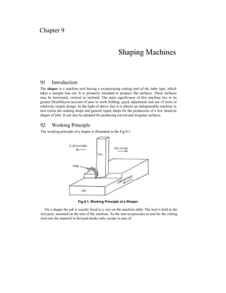
  • 1. Chapter 9 Shaping Machines 9.1 Introduction The shaper is a machine tool having a reciprocating cutting tool of the lathe type, which takes a straight line cut. It is primarily intended to produce flat surfaces. These surfaces may be horizontal, vertical or inclined. The main significance of this machine lies in its greater flexibilityon account of ease in work holding, quick adjustment and use of tools of relatively simple design. In the light of above fact it is almost an indispensable machine in tool rooms die making shops and general repair shops for the production of a few identical shapes of jobs. It can also be adopted for producing curved and irregular surfaces. 9.2 Working Principle The working principle of a shaper is illustrated in the Fig.9.1. Fig.9.1. Working Principle of a Shaper On a shaper the job is usually fixed in a vice on the machine table. The tool is held in the tool post, mounted on the ram of the machine. As the ram reciprocates to and for the cutting tool cuts the material in forward stroke only except in case of
  • 2. 9.2 draw cuts shaper, in which the tool cuts in backward stroke of the ram. The other stroke in both the cases remains idle, as there is no cutting action in this stroke and hence termed as idle strokes. 9.3 Types of Shapers Shapers are classified in a number of ways depending upon the general features of design or the purpose for which they are intended. Shapers are classified under the following headings. 1) According to the type of mechanism used for giving reciprocating motion to the ram (a) Crank type (b) Geared type (c) Hydraulic type 2) According to the position and travel of ram (a) Horizontal type (b) Vertical type (c) Traveling head type 3) According to the type of design of the table: (a) Standard shaper (b) universal shaper 4) According to the type of cutting stroke (a) Push type (b) Draw type 9.3.1 Crank Shaper This is the most common type of shaper in which a single point cutting tool is given' a reciprocating motion equal to the length of the stroke desired while the work is clamped in position on an adjustable table. In construction, the crank shaper employs a crank mechanism to change circular motion of a large gear called "bull gear" incorporated in the machine to reciprocating motion of the ram. The bull gear receives power either from an individual motor or from an overhead line shaft if it is a belt driven shaper. 9.3.2 Geared type The reciprocating motion of the ram in some type of shaper is effected by means of a rack and pinion. The rack teeth, which are cut directly below the ram, mesh with a spur gear. The pinion meshing with the rack is driven by a gear train. The speed and the direction in which the machine will traverse depend on the number of gears in the gear train. This type of shaper is not very widely used. 9.3.3 Hydraulic Shaper In a hydraulic shaper reciprocating movement of the ram is obtained by hydraulic power. Oil under high pressure is pumped in to the operating cylinder fitted with a piston. The end of the piston rod is connected to the ram. The high-pressure oil first acts on one side of the piston and then on the other causing the piston to reciprocate and the motion is transmitted to the ram. The piston speed is changed by varying the amount of liquid delivered by the pump. One of the most important advantages of this type of shaper is that the cutting speed and force of the ram drive are constant
  • 3. Shaping Machines 9.3 from the very beginning to the end of the cut. It also offers great flexibility up of motion when the cutting tool is overloaded. Protecting the parts or the tools from breakage. Another advantages is that the machine does not make any noise and operates very quietly. 9.3.4 Horizontal Shaper In a horizontal shaper, the ram holding the tool reciprocates in a horizontal axis. Horizontal shapers are mainly used to produce flat surfaces. 9.3.5 Vertical Shaper In a vertical shaper, the ram holding the tool reciprocates in a vertical axis. In some of the vertical machines provision is made to allow adjustment of the ram to an angle of about 10 degrees from the vertical position. Vertical shapers may be crank driven, rack driven, screw driven or hydraulic power driven. The work table of a vertical shaper can be given cross, longitudinal, and rotary movement. The tool used on a vertical shaper is entirely different from that used on a horizontal shaper. Vertical shapers are very convenient for machining internal surfaces, keyways, slots or grooves; large internal and external gears may also be machined by indexing arrangement of the rotary table. There are vertical shapers, which are specially designed for machining internal keyways. They are then called keyseaters. 9.3.6 Travelling Head Shaper In a travelling head shaper, the ram carrying the tool while it reciprocates moves crosswise to give the required feed. Heavy and unwiedly jobs, which are very difficult to hold on the table of standard shaper and fed past the tool are, held static on the basement of the machine while the ram reciprocates and supplies the feeding movements. 9.3.7 Standard or Plain Shaper A shaper is termed as standard or plain when the table has only two movements, vertical and horizontal, to give the feed. The table may or may not be supported at the outer end. 9.3.8 Universal Shaper In a universal shaper in addition to the two movements provided on the table of a standard shaper, the table can be swivelled about an axis parallel to the ram ways, and the upper portion of the table can be tilted about a second horizontal axis perpendicular to the first axis. As the work mounted on the table can be adjusted in different planes, the machine is most suitable for different types of work and is given the name "universal". A universal shaper is mostly used in tool room work. 9.3.9 Push Type Shaper This is the most general type of shaper used in common practice. The metal is removed when the ram moves away from the column, i.e., pushes the work.
  • 4. 9.4 9.3.10 Draw Type Shaper In a draw shaper, the metal is removed when the ram moves towards the column of the machine, i.e., draws the work towards the machine. The tool is set in a reversed direction to that of a standard shaper. The ram is generally supported by an overhead arm which ensures rigidity and eliminates deflection of the tool. In this shaper the cutting pressure acts towards the column which relieves the cross rail and other bearings from excessive loading and allows to take deep cuts. Vibration in these machines is practically eliminated. 9.4 Principal Parts 9.4.1 Base The base is the necessary bed or support required for all machine tools. The base may be rigidly bolted to the floor of the shop or on the bench according to the size of the machine. It is so designed that it can take up the entire load of the machine and the forces set up by the cutting tool over the work. It is made of cast iron to resist vibration and take up high compressive load. 9.4.2 Column The column is a box like casting mounted upon the base. It encloses the ram driving mechanism. Two accurately machined guide ways are provided on the top of the column on which the ram reciprocates. The front vertical face of the column contains levers, handles, etc, for operating the machine. Fig.9.2. Illustrates different parts of a standard shaper
  • 5. Shaping Machines 9.9 1) Table support 2) Table 3) Clapper box 4) Apron clamping blots 5) Down feed hand wheel 6) Swivel base degree graduations 7) Position of stroke adjustment hand wheel 8) Ram block locking handle 9) Ram 10) Column 11) Driving pulley 12) Base 13) Feed disc 14) Pawl mechanism 15) Elevating screw. 9.4.3 Cross rail The cross rail is mounted on the front vertical guide ways of the column. It has two parallel guide ways on its top in the vertical plane that are perpendicular to the ram axis. The table may be raised or lowered to accommodate different sizes of jobs by rotating an elevating screw which causes the cross rail to slide up and down on the vertical face of the column. A horizontal cross feed screw which is fitted within the cross rail and parallel to the top guide ways of the cross rail actuates the table to move in a crosswise direction. 9.4.4 Saddle The saddle is mounted on the crossrail which holds the table firmly on its top. Crosswise movement of the saddle by rotating the cross feed screw by hand or power causes the table to move sideways. 9.4.5 Table The table, which is bolted to the saddle receives cross wise and vertical movements from the saddle and crossrail. It is a box like casting having T-slots both on the top and sides for clamping the work. In a universal shaper the table may be swiveled on a horizontal axis and the upper part of the table may be tilted up or down. In a heavier type shaper, the front face of the table is clamped with a table support to make it more rigid. 9.4.6 Ram The ram is the reciprocating member of the shaper. This is semi-cylindrical in from and heavily ribbed inside to make it more rigid. It slides on the accurately machined dovetail
  • 6. 9.6 guideways on the top of the column and is connected to the reciprocating mechanism contained within the column. It houses a screwed shaft for altering the position of the ram with respect to the work and holds the tool head at the extreme forward end. 9.4.7 Tool head The tool head of a shaper holds the tool rigidly provides vertical and angular feed movement of the tool and allows the tool to have an automatic relief during its return stroke. The vertical slide of the tool head has a swivel base, which is held on a circular seat on the ram. The swivel base is graduated in degrees, so that the vertical slide may be set perpendicular to the work surface or at any desired angle. By rotating the downfeed screw handle, the vertical slide carrying the tool executes downfeed or angular feed movement while machining vertical or angular surface. The amount of feed or depth of cut may be adjusted by a micrometer dial on the top of the downfeed screw. Apron consisting of clapper box, clapper block and tool post is clamped upon the vertical slide by a screw. By releasing the clamping screw the apron may be swivelled upon the apron swivel pin either towards left or towards right with respect to the vertical slide. This arrangement is necessary to provide relief to the tool while making vertical or angular cuts. The two vertical walls on the apron called clapper box houses the clapper block, which is connected to it by means of a hinge pin. The tool post is mounted upon the clapper block on the forward cutting stroke the clapper block fits securely to the clapper box to make a rigid tool support on the return stroke a slight frictional drag of the tool on the work lifts the block out of the clapper box a sufficient amount preventing the tool cutting edge from dragging and consequent wear. The work surface is also prevented from any damage due to dragging. Fig.9.3 illustrates the tool head of a shaper. 1) Down feed screw micrometer dial 2) Down feed screw 3) Vertical slide 4) Apron 5) Apron clamping bolt 6) Clapper block 7) Tool post 8) Washer 9) Apron swivel pin 10) Swivel base. 9.5 Shaper Size and Specification The size of shapers is classified according to the maximum length of stroke. Push-cut shapers can accept work sizes from 102-to 915 mm. Pull-cut shapers are made for Fig.9.3. Tool head of a shaper
  • 7. Shaping Machines 9.7 work reguirments up to 1.82 m. The maximum cross-feed distance is generally equiva- lent. The maximum ram stroke, distance. Therefore, a shaper with a 406mm maximum stroke, for example, is capable of machining a part with a plane surface that measures at least 406 mm x 406 mm square. 9.5.1 Specifications of a shaper Maximum ram stroke 700mm Maximum tool overhang 840 mm Distance between table surface and ram Maximum 400mm Minimum 80 mm Dimensions of table working surface 700 mm x 450 mm Maximum travel of table Horizontal 700 mm Vertical 320 mm Horizontal feed per double stroke 0.25-5 mm Principal movement motor power 7 kW Overall dimensions 2785 x 1750 x 1780 mm. 9.6 Shaper Driving Mechanism In a shaper, rotary movement of the drive is converted into reciprocating movement by the mechanism contained within the column of the machine. The ram holding the tool gets the reciprocating movement. In a standard shaper the metal is removed in the forward stroke and the return stroke is idle. The time taken by idle stroke is merely waste and should be minimised as far as possible. This can achieved by making the shaper to complete its return stroke quicker than the forward one. Thus the shaper mechanism should be so designed to perform the cutting stroke at a comparatively shower speed than the return stroke and this mechanism is known as quick return mechanism. The reciprocating movement of the ram and the quick return mechanism of the machine are usually obtained by any one of the following. 1) Crank and slotted lever mechanism 2) Whit-worth quick return mechanism 3) Hydraulic shaper mechanism 9.6.1 Crank and Slotted Lever Mechanism The crank and slotted lever mechanism is shown in the Fig.9.4. It consists of slotted link called rocker arm. The rocker arm is pivoted at its bottom end which forms the fulcrum. At its upper it carries another short link which is attached to the ram block (B). The ram block (B) can be clamped at the desired position by hand lever (L). The rocker arm is provided with a sliding block (QJ in which the crank pin (P) revolves. The sliding block can freely slide in the slot provided in the rocker arm. At the back
  • 8. 9.8 of the rocker arm a large gear wheel known as bull gear is provided. The motion of the power is transmitted to the bull gear through a pinion, which receives its motion from an individual motor or overhead line shaft through speed control mechanism. A slotted disc (D), carrying a T-slot is fitted to the bull gear at its front, the crank pin 'P' is fitted in this slot and can be moved to any desired piston along the slot by means of the bevel gears (BJ and (B2) and adjusting screw (S). The bevel gears (B2) is concentric with the bull gear and the other bevel gear (BJ is attached to the lead screw (S) at its one ends as shown in the Fig. The axes of bevel gears (BJ and (B2) are at right angles to each other and called as miter gears. Fig.9.4. Crank and slotted lever mechanism As the bull gear rotates causing the crank pin (P) to rotate, the sliding block (Q) fastened to the crank pin (P) will rotate on the crank pin circle and at the same time will move up and down the slot in the rocker arm giving it rocking movement which makes the rocked arm to swing about the fulcrum. Thus in turn the rocker arm moves the ram to and fro. 9.6.1.1 Principle of Quick Return Mechanism The principle of quick return mechanism is illustrated in Fig.9.5. When the link is in the position OQ2, the ram will be at the extreme backward position of the stroke and when it is at OQ2, it has reached the extreme forward position. Therefore the forward cutting stroke takes place when the crank rotates through the angle Pa, K P2, and the return stroke takes place when the crank rotates through the angle P2, L Pr
  • 9. Shaping Machines 9.9 It is very clear that the angle P , KP2 made by the cutting stroke (forward stroke) is greater than the angle P2, LP] made by the return stroke. The angular velocity of the crank pin is constant. Therefore the return stroke is completed within a shorter time than the cutting stroke for which it is known as quick return motion. The ratio between these two angles, and hence between the corresponding times is approximately 3:2. Fig.9.5. Principle of quick return mechanism 9.6.1.2 Adjusting the Length of the Stroke and Ram Position The stroke length is varied by varying the distance between the bull gear center (A) and the crank pin (P). By rotating the bull gears (B2) and (BJ the screwed shaft is rotated which moves the sliding block and hence the crank pin, towards or away the bull gear center depending upon the stroke length is required to be reduced or increased as shown in the shown in the Fig.9.6 (a) and (b). (a) (b) Fig.9.6. Adjustment in the length of stroke The position of ram relative to the work can be adjusted by loosening the clamp holding the connecting link and rotating the hand wheel (H) which is at the end of the screwed shaft as shown in the Fig. Thus the ram is adjusted to the required position by rotating screwed shaft (M) through bevel gears (B3) and (B4).
  • 10. 9.10 9.6.2 Whit-Worth Quick Return Mechanism The line diagram of a whit worth quick return mechanism is shown in the Fig.9.7. In this mechanism the bull gear is mounted on a large fixed pin (A) upon which it is free to rotate. The slotted link (SOQ) is pivoted eccentrically upon the fixed pin at 'O'. The crank pin (P) is fitted, on the face of the bull gear and on the top of which the sliding block (S) is mounted. The sliding block (S) fits into the slot of the link. At the end of the slotted link SOQ, a connecting rod QR is connected by a pin Q. The ram (R) is connected to the other end of the connecting rod. When the bull gear rotates at a constant speed the crank pin (P) with the sliding block (S) will cause the slotted link to rotate about the point O with variable angular velocity. The pin (Q) fitted on the other end of the sloted link SOQ will rotate in a circle and the rotary motion of the pin Q will be converted into reciprocating movement of the ram similar to the crank slotted link mechanism. The axis of reciprocation of the ram passes through the pin O and is normal to the line AO. Fig.9.7. Whit-worth quick return mechanism If the crank (AP) rotates counter clockwise and when the crank pin (P) is at the position (PJ the ram will be at !:he extreme back ward position but when the pin is at the position P2 the ram will be at the extreme forward position. Thus when the crank pin (P) travels from Pl to P2 in counter clock wise direction the ram performs the return stroke and when it is from P2 to P1 it performs the cutting stroke. As the angular velocity of the crank pin is uniform, the time taken by the crank pin (P) to travel through the angle P2 LP: is greater than the time taken to move through the angle P MP . Thus the quick return motion is obtained. 9.6.3 Hydraulic Mechanism The simple mechanism of a hydraulic drive is shown in the Fig.9.8. In a hydraulic shaper the ram is moved forward and backward by a piston moving in a cylinder
  • 11. Shaping Machines 9.11 placed under the ram. The machine mainly consists of a constant discharged oil pump, a valve chamber, a cylinder and a piston. A constant speed motor drives the pump, which delivers oil at a constant pressure to the line. The regulating valves located in valve chamber, actuated by the machine and timed to the stroke, admits oil under pressure to each end of piston alternately and at the same time allowing oil from the opposite end of the piston to return to the reservoir. As the piston moves it. Although it is a constant pressure system under varying load condition the tool moves with different velocities. One end of the piston is having larger area and the other end has less area due to piston rod. Therefore it moves in one stroke at low speed (cutting stroke) and in opposite stroke (Return stroke) it moves at high speed. The velocity can also be controlled regulating the quantity of oil by feed handle as shown in Fig.9.8. Fig.9.8. Hydraulic Shaper 9.7 Advantages of Hydraulic Shaper Over Mechanical Shaper The hydraulic mechanisms are becoming popular because of the following advantages. 1) Ability to slip in case of over load 2) Smoother operation 3) Ability to withstand shock without damage to the tool or the machine 4) Infinite number of cutting speeds can be obtained from zero to the maximum value and the control easier. 5) Possibility of changing speed and feed during operation.
  • 12. 9.12 9.8 Table Feed Mechanism The automatic cross feed mechanism incorporated to the shaper table is shown in the Fig.9.9. The cross feed of table may be obtained manually or by power. In the latter case the table cross feed screw is rotated through certain degrees with the help of a ratchet wheel mounted on the cross feed screw. The complete mechanism is as follows. In consists of a slotted disc which carries a T slot as shown in the Fig.9.9. In this slot an adjustable pin is fitted and to which the connecting rod is attached. The other end of the connecting rod is attached to the lower end of the rocker arm of the pawl mechanism. The rocker arm swings about the cross feed screw and at its upper end carries a spring loaded pawl. The adjustable pin is set eccentric with slotted link disc centre. The slotted disc at its back carries a spur gear, which is driven by the bull gear. As the disc rotates through gear the adjustable pin that is eccentric to the disc centre, causes the connecting rod to reciprocate. This inturn makes the pawl over one or more teeth and thus transmits an intermittent motion to the cross feed screw which moves the table. The lower end of the pawl is beveled on one side. This facilitates the power feed to operate in either direction. The feed can be varied by varying the distance or between the disc centre and the centre of the adjustable pin. The larger the said distance, greater will be the feed and vice-versa. Fig.9.9. Table automatic cross feed mechanism 9.9 Work Holding Devices The top and sides of the table of a shaper have T-slots for clamping the work. The work may be supported on the table by the following methods depending on the nature of the work-piece.
  • 13. Shaping Machines 9.13 1) Clamped in a Vise 2) Clamped on the table 3) Clamped to the angle plate 4) Clamped on a V-block 5) Held between shaper index centre, 9.9.1 Shaper Vises Fig.9.10 illustrates a typical shaper vise. A vise is a quick method of holding and locating relatively small and regular shaped work-pieces. It consists of a base, table, screw, fixed and movable jaws. The base has a projection or tongue which fits in to the slot of the machine table. For properly securing it to the table lugs are provided for clamping the vise by T-bolts. The work is clamped between fixed and movable jaws by rotating the screw. Wherever possible the vise is so placed on the table that the tool while cutting exerts direct pressure upon the jaws. A machine vise may be classified under following headings. Fig.9.10. Shaper Vise 1) Plain vise a) Single screw b) Double screw 2) Swivel vise 3) Universal vise.
  • 14. 9.14 9.9.1.1 Plain Vise A plain vise is the most simple of all the types. The vise may have a single screw or double screws for actuating the movable jaw. The double screws add gripping strength while taking deeper cuts or handling heavier jobs. 9.9.1.2 Swivel Vise In a swivel vise the base is graduated in degrees and the body of the vise may be swivelled at any designed angle on a horizontal plane. The swivelling arrangement is useful in bevelling the end of work-piece. 9.9.1.3 Universal Vise A universal vise may be swivelled like a swivel vise. In addition to that, the body may be tilted in a vertical plane up to 90 degrees from the horizontal. An inclined surface may be machined by a universal vise. 9.9.2 Parallels Fig.9.10 illustrates the use of parallels. When the height of the job is less than the height of the jaws of the vise, parallels are used to raise and seat the work-piece above the vise jaws and parallel with the vise bottom. Parallels are square or rectangular bars of steel or cast iron, hardened and ground with opposites sides parallel. They are available in various sizes for seating work-pieces of different heights and are always used in pairs. 9.9.3 Hold Downs Fig.9.10 illustrates the use of hold downs. Hold downs or grippers are used for holding thin pieces of work in a shaper vise. Hold downs are also used for holding work of smaller height than the vise jaws where suitable parallels are not available. The hold down is a hardened wedge shaped piece with its two working edges tapered at an angle of 5°. Hold downs are placed between two jaws of the vise and the work piece. When the screw is tightened the typical shaped of the hold down exerts down ward pressure on the work to hold it tight on the parallels or on the vise table. 9.9.4 Clamping Work on the Table When the work-piece is too large to be held in a vise it must be fastened directly on the shaper table. In holding work on the table, clamping bolts should not be unduly tightened to produce distortion of the work. The different methods employed to clamp different types of work on a shaper table are: 1) T-bolts and clamps 2) Stop pins 3) Stop pins and toe dogs 4) Strip and stop pins.
  • 15. Shaping Machines 9.15 9.9.4,1 T-Bolts and Clamps Fig.9.11 illustrates the use of T-bolts and clamps for holding the work. T-bolts having T-heads are fitted in the T-slots of the table. The length of the threaded portion is sufficiently long in order to accommodate different heights of work. The clamps are made of steel having slots at the centre for fitting the bolt. One end of the clamp rests on the side of the work while the other end rests on a fulcrum block. The fulcrum block should be of the same height as the part being clamped. The bolt is placed as near to the work as possible and the nut is then tightened. To hold a large work on the table a series of clamps and T-bots are used all round the work. Fig.9.11. Use of T-bolt and clamp 9.9.4.2 Stop Pins Fig.9.12 illustrates stop pins. A stop pin is a one-leg screw clamp. As the tool moves forward to perform cutting stroke the work tends to be pushed out of its position under the pressure of the cutting tool. Stop pins are used to prevent the work from coming out of position. The body of the stop pin is fitted in the hole or slot on the table and the screw is tightened till it forces against the work. Fig.9.12. Stop Pins
  • 16. 9.16 9.9.4.3 Stop Pins and Toe Dogs Fig.9.13.illustrates the use of the stop pins and toe dogs, while holding thin work on the table stop pins in conjunction with toe dogs are used. A toe dog is similar in shape to that of a centre punch or a cold chisel. The head end of a toe dog is drilled slightly so that the end of the stop pin screw may fit in to it.Fig.9.14 shows two types of toe dogs. A large number of stop pins and toe dogs are placed are round the work. When screw of the stop pin is tightened. The work is gripped down on the table. Fig.9.13. Use of stop pin and toe dog Fig.9.14. Toe dog 9.9.4.4 Strip and stop pins Fig. 9.15 illustrates the working of strip and stop pins for holding the work. Work having sufficient thickness is held on the table by strip and stop pins. A strip is a long bar having a tongue with holes for fitting the T-bolts. The strip with bolts is fitted in the T-slot of the table, the tongue of the strip fitting within the slot. The nuts are then tight- ened so that the strip plate may rest on one side of the work. The stop pin screws are then tightened end of the work so that the work may be clamped between stop pins and strip plate. 9.9.5 Angle Plate Fig.9.16 illustrates the use of an angle plate. For holding 'U shaped work- piece, angle plates are used. Angle plates are made of cast iron and is planed on two sides to an angle of ex- actly 90°. One of the sides is clamped to the table by T-bolts while the other side holds the work by clamps. Fig.9.15. Use of strip and stop pins Fig.9.16. Use of an angle plate
  • 17. Shaping Machines 9.17 9.9.6 V-Block Fig.9.17 illustrates the use of a V-block. For holding round rods V-block are used. Work may be supported on two V-blocks at its two ends and is clamped to the table by T-bolts and clamps. The tool may be made to reciprocate between the two clamps for cutting grooves or key ways. V-blocks are made of cast iron or steel and are accurately machined. Fig.9.17. Use of V-block 9.9.7 Shapers centers Fig.9.18 illustrates a shaper center. This is a special attachment used for cutting equally spaced grooves or splines on the periphery of a round work. In special cases, it may be used for cutting gears. A shaper centre consists of a headstock and atailstock and the work is mounted between two centres. Mounted upon the head- stock spindle is the worm gear 4, which meshes with the worm. The handle 2 is connected with the worm shaft. Rotation of the handle 2 causes the worm gear 4 to rotate and the motion is transmitted to the work through a catch plate and carrier. After cutting a slot or groove on the top of the work, it may be turned to a predeter- mined amount by an index plate 3 and index pin. The index plate is mounted on the worm gear shaft. The index plate has a series of holes around its circumference and is locked in any a desired position by engaging the index pin in the corresponding hole. Index plates are provided with various numbers of holes. Fig.9.18. Use of shaper centre 9.10 Shaper Operations A shaper is a versatile machine tool primarily designed to generate a flat surface by a single point cutting tool. But it may also be used to perform many other operations. The different operations, which a shaper can perform are as follows: 1) Machining horizontal surface
  • 18. 9.18 2) Machining vertical surface 3) Machining angular surface 4) Cutting slots, grooves, and key ways 5) Machining irregular surface 6) Machining splines or cutting gears. 9.10.1 Machining horizontal surface Fig.9.19 illustrates machining horizontal surface on a workpiece. A shaper is mostly used to machine a flat, true surface on a work-piece held in a vise or other holding devices. After the work is properly held on the table, a planing tool is set in the tool post with minimum overhang. The table is raised till there is a clearance of 25 to 30 mm between the tool and the work-piece. The length and position of stroke are then adjusted. The length of stroke should be nearly 20mm longer than the work and the position of stroke is so adjusted that the tool begins to move from a distance of 12 to 15 mm before the begining of the cut and continues to move 5 to 8mm after the end of the cut proper cutting speed and feed is then adjusted. Short, strokes should be given with high speed while long strokes with slow speed. Both roughing and finishing cuts are performed to complete the job. For roughing cut speed is decreased but feed and depth of cut is increased. Depth of cut is adjusted by a micrometer dial. The depth of cut for roughing work usually ranges from 1.5 to 3mm, while for finishing work it ranges from 0.075 to 0.200 mm. Feed is adjusted about one half the width of the cutting edge of the tool so that each cut will over lap the last cut giving a smooth surface finish. Fig.9.19. Machining horizontal Fig.9.20. Machining vertical surface surface 9.10.2 Machining vertical surface Fig.9.20 illustrates machining vertical surface on a work-piece. A vertical cut is made while machining the end of a work-piece, squaring up a block or cutting
  • 19. Shaping Machines 9.19 shoulder. The work is mounted in the vise or directly on the table and the surface to be machined is carefully aligned with the axis of the ram. A side-cutting tool is set on the tool post and the position and length of stroke is adjusted. The vertical slide is set exactly at zero position and the apron is swiveled in a direction away from the surface being cut. This is necessary to enable the tool to move upwards and away from the work during return stroke. This prevenets the side of the tool from drag- ging on the planed vertical surface during return stroke. The down feed is given by rotating the down feed screw by hand. The feed is about 0.25mm given at the end of the each return stroke. Both roughing and finishing cuts are performed to complete the job. 9.10.3 Machining angular surface Fig.9.21 illustrates machining of an angular surface on a work-piece. An angular cut is made at any angle other than a right angle to the horizontal or to the vertical plane. The work is set on the table and the vertical slide of the tool head is swivelled to the required angle either towards left or towards right form the vertical position. The apron is then further swivelled away from the work so that the tool will clear the work during return stroke. The down feed is given by rotating the down feed screw. Angular surface can also be machined in a universal shaper by using a universal vise without swivelling the tool head. Fig.9.21. Machining angular surface 9.10.4 Cutting slots and keyways With suitable tools a shaper can very conveniently machine slots or grooves on a work or cut external keyways on shafts and internal keyways on pulleys or gears. For cutting slots or keyways a square nose tool similar to a parting tool is selected. Fig.9.22 illustrates cutting of external keyways and Fig.9.23 shows cutting of internal keyways in a shaper. External keyways are cut on a shaft by first drilling a hole at the blind end of the keyway. The diameter of the holes should be 0.5 to 0.8mm over
  • 20. 9.20 size than the width of the keyways and the depth should be about 1.55mm larger than the depth of keyway. This is necessary to leave a clearance on the tool at the end of the stroke. The length and position of stroke is carefully adjusted so that the stroke will terminate exactly at the clearance hole. The speed is reduced while cutting a keyway. Internal keyways are cut by holding the tool on a special tool holder so that the tool post will not hit against the work at the end of the stroke. The clapper block is locked in the clapper box to prevent the tool from lifting during return stroke. Lubrication is necessary on the work to prevent the cutting edge of the tool from wear due to dragging. Fig.9.22. Cutting external keyway Fig.9.23. Cutting internal keyway 9.10.5 Machining Irregular Surface A shaper can also produce a contoured surface i.e. a convex or concave surface or a combination of any of the above surfaces. To produce a small contoured surface a forming tool is used. If the curve is sufficiently large power. Cross feed in conjunction with manual down feed is so adjusted that the tool will trace the required contour. If the contour has too many ups and downs both the feeds are operated by hand. A round nose tool is selected for machining irregular surfaces. Fig.9.24. Machining irregular For a shallow cut the apron may be set vertical surface but it the curve is quite sharp, the apron is swivelled towards right or left away from the surface to be cut. Fig. Shows machining of a concave surface using a round nose tool. 9.10.6 Machining Splines or Cutting Gears By using an index centre illustrated in Fig.9.18, a gear or equally spaced spline may be cut. The work is mounted between two centers and a spline is cut similar to the cutting of a keyway. After the first spline is cut, the work is rotated through a prede- termined amount by using the index plate and index pin. The periphery of a gear
  • 21. Shaping Machines 9.21 blank is divided, and equally spaced grooves are cut using an index plate having proper hole circles, while cutting gear formed tool is used. 9.11 Shaper Tools The cutting tool used in a shaper is a single point cutting tool having rake, clearance and other tool angles similar to a lathe tool. It differs from a lathe tool in tool angles. Shaper tools are much more rigid and heavier to withstand shock experienced by the cutting tool at the commencement of each cutting stroke. In a lathe tool the effective angle of rake and clearance may be varied by raising or lowering the point of the tool in relation to the centre of the work nut in a point of the tool in relation to the centre of the work, but in a shaper the tool angles cannot be changed as the tool is always clamped perpendicular to the surface of the work. When it becomes necessary to change the tool sufficient amount of side clearance angle must be provided as the tool is continually fed sideways tracing a helical path, but in a shaper tool as the feed is given at the end of cutting stroke, a very small clearance angle is necessary to give relief to the side cutting edge. In a shaper tool the amount of side clearance angle is only 2° to 3° and the front clearance angle is 4° for cast iron and steel. Small clearance angle adds strength to the cutting edge. As the tool removes metal mostly from its side cutting edge, side rake. The side rake angle to be provided is dependent upon the kind of metal being cut, the hardness of the tool material, type of cut, roughing or finishing and other factors which influence the rake angle. A shaper can also case a right hand or left hand tool. The left hand tool is more common because it permits the operator to see the cut better than the right hand tool. High-speed steel is the most common material for a shaper tool but shock resistant cemented carbide tipped tool is also used where harder material is to be machined. As in a lathe, tool holders are also used to hold the bits. Some of the most common cutting tools are: 1) A left hand roughing tool for planning (Fig.9.25) Fig.9.25. A left hand roughing tool for planning
  • 22. 9.22 2) A left hand finishing tool for planning (Fig.9.26) Fig.9.26. A left hand finishing tool for planning 3) A left hand side facing tool for vertical shaping and for shaping sharp corner (roughing) (Fig.9.27) Fig.9.27. A left hand side-roughing tool 4) A left hand side tool (finishing) (Fig.9.28) Fig.9.28. A left hand side-finishing tool
  • 23. Shaping Machines 9.23 9) A left hand dovetail cutting tool (roughing) (Fig.9.29) Fig.9.29. A left hand dovetail cutting tool for roughing 6) A left hand dovetail-cutting tool (finishing) (9.30) Fig.9.30. A left hand dovetail cutting tool for finishing 7) A parting or slotting tool (Fig.9.31) Fig.9.31. A parting or slotting tool
  • 24. 9.24 9.12 Cutting Speed, Feed and Depth of Cut 9.12.1 Cutting Speed In a shaper the cutting speed is the rate at which the metal is removed by the cutting tool. This is expressed in meter per minute. In a lathe as the cutting action is continuous the cutting speed is expressed by the peripheral speed of the work. But in a shaper the cutting action is intermittent. In a shaper the cutting speed is considered only during the forward cutting stroke. 9.12.1.1 Cutting Speed Calculations The cutting speed in a shaper is expressed by the formula In practice to calculate the cutting speed, it is difficult to measure exactly the time taken during the forward cutting stroke. The ratio between the return time to cutting time and the number of double strokes per minute or r.p.m. of the bull wheel should be known. The cutting speed may be obtained from the equation. Let, L = The length of cutting stroke in mm. m = The ratio between return time to cutting time. n = The number of double strokes of the rpm per minute or r.p.m. of the bull wheel v — The cutting speed expressed in m/min. From the equation (1) or return stroke time = m x cutting stroke time (2) Time taken to complete one double stroke
  • 25. Shaping Machines 9.25 Number of double strokes per minute (or) The cutting speed so calculated is the average cutting speed as it has been assumed that the cutting stroke is completed at a uniform speed, but in reality, in a crank driven shaper cutting speed and return speed is not uniform. The factors which govern the amount of cutting speed are same as the discussed Example. 9.1 In a shaper work, the length of stroke is 200mm,'number of double strokes per mintue is 30 and the ratio of return time to cutting timeis 2:3 Find the cutting speed. Cutting speed = nL(l+ m) 1000 30x200[l + ^ 1000 30 x 200 x 5 = 10m/min. 9.12.2 Feed Feed (S) is the relative movement of the tool or work in a direction perpendicular to the axis of reciprocation of the ram per double stroke and is expressed in mm. The feed is always given at the end of return stroke when the tool is not cutting the metal. The selection of feed is dependent upon the kind of metal, type of job etc. 9.12.3 Depth of cut Depth of cut (t) is the thickness of metal that is removed in one cut. It is the perpendicular distance measured between machined surface and non-machined surface of the work-piece. 1000 x 3
  • 26. 9.26 Metal Cutting & Machine Tools 9.13 Machining Time If the length of cutting stroke, breadth of the job, feed and cutting speed are known, the time required to complete the job may be calculated as: Let, ' L = The length of the stroke in mm. B = The breadth of the work in mm. s = The feed expressed in mm/double stroke. m = The ratio return time to cutting time. v = The cutting speed in m/min. Then from equation (3). Time taken to complete one double stroke = Total number of double strokes required to complete the job = — .-. Total time taken to complete the cut = Example 9.2 Find the time required for taking a complete cut on a plate 600 x 900 mm, if the cutting speed is a m/min. The return time to cutting time ratio is 1:4 and the feed is 3mm. The clearance at each end is 75mm. In a shaper a stroke length of more than 900mm is not ordinarily available so the work is placed on the table to take a cut of 600mm plus the clearances. Total length of stroke = 600 + 75 + 75 = 750 mm. Cutting time = Total time for one complete double stroke = Total number of double strokes necessary to complete the cut =
  • 27. Shaping Machines 9.27 , Total time required to complete the cut = Table.9.1: Average value of cuting speed and feed High carbon steel High speed steel tool Cemented carbide Material V m/min S mm V m/min S mm V m/min S mm Cast iron Mild steel Brass 9 12 30 1.5 12.5 1 18 24 48 2 1.5 1.25 30 45 60 0.125-0.5 0.125-0.5 0.25-0.35