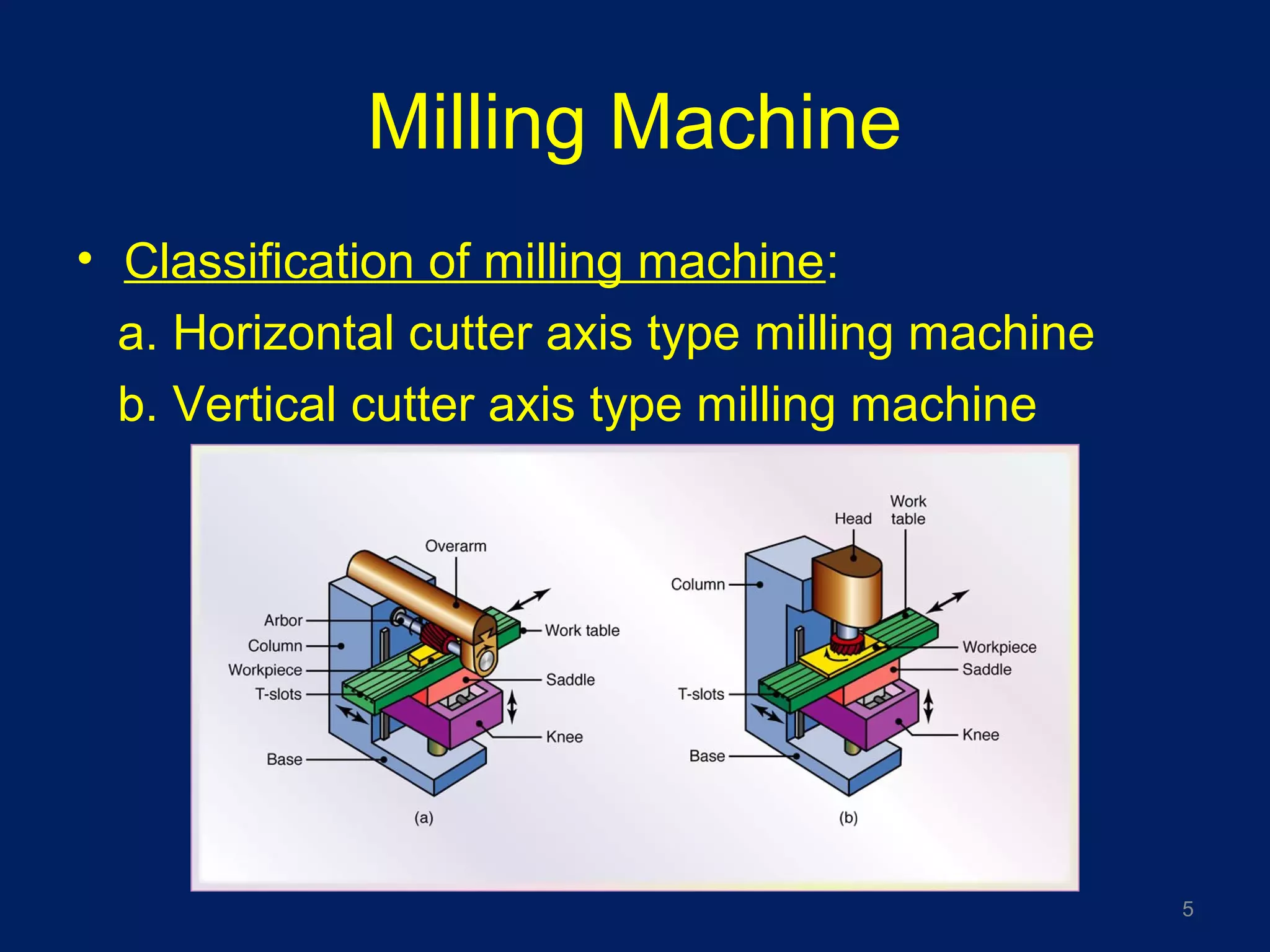
SlideShare a Scribd company logo
Milling & Gear Cutting
1
Mr. KONAL SINGHMr. KONAL SINGH
Director and Founder of
ProBotiZ Group, NagpurProBotiZ Group, Nagpur
(W) - Probotizgroup.com (M) - 8862098889, 9423632068 (E) - probotizinfo@gmail.com
Syllabus
• Milling – Cutting parameters, machine time
calculation
• Milling operation – Plain milling, side & face
milling, form milling, gang milling, end milling,
face milling, T slot milling, slitting
• Gear Cutting – Gear cutting on milling
machine – dividing head and indexing method,
gear hobbing, principle of operation, advantages
& limitation, hobbing tech, gear shaping, gear
finishing process
2
Learning Objective
• Details of milling machine, understand the
various process used and different function etc.
• Understand the gear tooth specification, gear
generating process, gear finishing process etc.
3
Milling Machine
• Milling machine: It is machine made up with the
different attachment like base, column, head /
overram, arbor (tool attachment), table, saddle,
Knee etc.
• Principle of operation: In this machine the work
piece is stationary & it is hold in a table whereas
the tool/ cutter are to be rotated about it own
axis and simultaneously the work piece are feed
against rotating cutter
4
Milling Machine
• Classification of milling machine:
a. Horizontal cutter axis type milling machine
b. Vertical cutter axis type milling machine
5
Milling machine
• Types of milling machine:
1.Column & knee type
2.Hand milling
3.Plain milling machine
4.Vertical, universal, general purpose, planner
5.Fixed bed type milling machine
6.Special type milling machine
6
Milling machine
• Types of work done on milling machine
7
Milling machine
• Milling Operation:
(a) Schematic illustration of conventional (up) milling and
climb milling (down). (b) lab-milling operation showing depth-
of-cut, d; feed per tooth, f; chip depth-of-cut, tc; and workpiece
speed, v. (c) Schematic illustration of cutter travel distance,
lc, to reach full depth-of-cut.
8
Milling machine
• Milling process
1.Milling is one of the basic
machining processes.
2.Milling is a very versatile
process capable of
producing simple two
dimensional flat shapes to
complex three
dimensional interlaced
surface configurations.
9
Milling machine
Milling Process
• Typically uses a multi-tooth
cutter
• Work is fed into the rotating
cutter
• Capable of high MRR
• Well suited for mass
production applications
• Cutting tools for this process
are called milling cutters
10
Milling machine
Plain milling machine
• It’s a more rigid m/c than
hand milling
Application
• It is used for Gang milling,
form milling, slotting,
keyways etc.
11
Milling machine
Vertical Milling machine
• It derives its name from the
vertical position of the
spindle
• Cutter used in this type are
End mill type
• Spindle head can be
swiveled to any desire
angle for machining
angular surfaces
12
Milling machine
Vertical Milling machine
Application
• It is used for profile cutting die
sinking
• Also useful for milling various
irregular shape
• In this m/c drilling boring
reaming and facing operation
can also be performed
13
Milling machine
Universal milling machine
• It is similar to plain
milling machine expect
here the table can be
swiveled horizontally
and can be fed angle to
the milling machine
spindle.
14
Milling machine
Universal milling machine
Application
• Accurate work can be
done in this tool room
m/c
• Milling cutter, twist drill
& straight and taper
work
15
Milling machine
Progressive milling
When two or more similar
or different operation are
to be performed either
simultaneous or
successively on
separate work piece
progressively moved
from one fixture to next
until all operation are
performed.
16
Milling machine
Angular milling
• This process is used to produce
angular surface on the work
piece
• The angle of cutting is other than
right angle
• The cutter used may be single or
double angle type
Application
• V block used in work shop
17
Milling machine
Planer (Plano – miller)
• It’s a largest size m/c
• It is used to machine
the flat surface
• it consist of a long
table having only a
longitudinal
movement
• It has a two vertical
column
18
Milling machine
Planetary milling
• In this m/c the work is held stationary while the
revolving cutter moves in circular path to machine
the surface
19
• At the start of the job the
rotating cutter is in centre
• It is fed radially to the
proper depth & than given
a planetary motion inside
or outside the work
Milling machine
Gang Milling
• If more than two cutter
are used together on the
arbor of milling machine
• The distance between
cutter is adjusted by
spacing of coller
20
Milling machine
T – Slot milling
Open slot – It can be produce by same cutter with
special attachment
Closed slot – It can be produced by End mill type
cutter
21
Milling machine
• Some other
milling processes
are
22
Milling machine
Straddle milling
• In this a pair of side milling are
used for machining two parallel
vertical surface on the work piece
simultaneously.
• It is a special form of gang milling
• Distance between two cutter are
adjusted by spacing collar
• It has its teeth on side and
periphery
23
Milling machine
Up Milling : It is based on direction of feeding work
piece and rotation of milling cutter
• In this milling process the cutter is rotated in a
direction opposite to the direction of travel of the
work piece
Down Milling : In this cutter is rotated in the same
direction as that of the travel of the work piece
24
Milling Cutter
Milling cutter can be classified as
1.plain milling
2.side milling
3.End milling
4.Metal slitting cutter
5.Face milling cutter
6.Angle milling cutter
7.Form milling cutter
8.Fly cutter
25
Milling Cutter
Elements of plain milling cutter
26
Milling Cutter
Cutter Angles
Milling cutter is provided with Rake angle,
Clearance angle, Lip angle similar to SPCT
1. Rake angle (Gama): It is the angle measured in
the diametric plane between the face of the
tooth and radial line passing through the tooth
cutting edge
27
Milling Cutter
Cutter Angles
2. Relief angle (Alpha): the angle in a plane
perpendicular to the axis, which is the angle
between the land of the tooth and the tangent to
the outside diameter of cutter at the cutting edge
of that tooth
3. Lip angle (Beta): the angle between the face
and land of the cutter tooth is called lip angle
28
Milling Cutter
What is negative rack milling
• If the face of milling cutter lies along a
radius of the cutter, it is said to have zero
rake.
• If the face of the cutter lies along either
line, on either side of the radius of the
tooth, it is a Positive rack.
• If the face of the cutter lies along either
line, on opposite side of the radius of the
tooth, it is a Negative rack.
29
Milling Cutter
Advantages of Negative rack angle
• It gives better finish
• Improved tool life by increased tip angle and it
can withstand shock load better way
• Negative rake strengthens the cutting edge and
produces higher force and requires more power
and is used in carbide cutter
• It causes the cutting force to fall with in the body
of the cutter
30
Milling Cutter
Plain milling Cutter
• Once widely used
• Cylinder of high-speed steel with
teeth cut on periphery
• Used to produce flat surface
• Several types
– Light-duty
– Light-duty helical
– Heavy-duty
– High-helix
31
Milling Cutter
Face milling cutter
• Generally over 6 in. in diameter
– Have inserted teeth made of high-speed steel
held in place by wedging device
• Most cutting action occurs
at beveled corners and
periphery of cutter
• Makes roughing and
finishing cuts in one pass
32
Milling Cutter
Shell End milling cutter
• In this cutting edge are
provided at the end and the
periphery of the cutter
• In this type teeth of the
cutter may be helical or
straight
• These cutter are used in
face milling operation
33
Milling Cutter
Slab milling cutter
• These cutter are cylindrical in
shape and have teeth on the
circumferential surface only
• The cutter are used to
produced flat surfaces parallel
to axis of spindle
34
Work
Milling Attachment
• Vertical milling attachment
• Universal milling attachment
• High speed milling attachment
• Rotary milling attachment
• Slotting attachment
• Dividing head attachment
35
Indexing Method
Universal dividing head
• It is a device used for indexing
the work
• A worm is attached to a main
spindle. The worm gear has 40
teeth & worm is single threaded,
so that 40 turn of crank will
rotate the spindle through one
complete revolution
• Index plate is fixed on the
spindle with locking pin and
connected to the crank
36
Indexing Method
• It’s used to obtain greater
number of divisions that can not
be obtained by direct indexing.
• It’s carried out using 40:1 ratio of
the worm and worm mechanism.
• Two sector arms fit on the face
of the indexing plate.
• The arms can be set a part to
cover a required number of
holes between them
37
Indexing
38
ELEMENTS OF GEAR
• Pitch circle.
• Circular pitch.
• Pitch circle diameter.
• Addendum circle.
• Root circle.
• Addendum.
• Dedendum .
• Hand.
• Clearance.
• Working depth.
• Flank of tooth.
39
ELEMENTS OF GEAR
• Addendum circle: The circle which limits the top
of the gear teeth & represent its maximum
diameter
• Addendum: It is the radial height of tooth above
the pitch circle
• Dedendum: It is the radial depth below pitch
circle and root circle
• Basic circle: It is the circle from which the
involutes curve of tooth profile is generated
• Pressure angle: It is a angle between tooth
profile and radial line and at its pitch point
• Pitch point: It is the point of contact between the
pitch circle of two mating gear
• Face: It is the side surface of tooth lying
between the pitch circle and addendum circle 40
ELEMENTS OF GEAR
• Flank: It is side surface of the tooth
lying between pitch circle and root
circle
• Module: It represent the ratio of the
pitch circle diameter to the number
of teeth on the gear
• M = (D / N)
• Diametrical pitch: It is the
number of teeth on the gear
per unit diameter of the pitch
circle
Diametric Pitch = Number of
teeth / Diameter of pitch circle 41
Gear Cutting Process
• In gear cutting process, the
cutter is formed according to the
shape of the tooth.
• The space to be removed
between two adjacent teeth by
FORM milling cutter
• The cutter is attached on the
mandrel and connected to
dividing head.
• The selection of cutter is depend
upon the size of gear tooth and
number of teeth 42
Roll of coolant in milling
• To remove chip, dirt, dust or any abrasive
particles from the work piece
• To reduce the heat generated during cutting
operation on and over the work piece
• Protect the distortion of work piece from any
affect of heat.
• Protect the work surface from corrosion
43
Cutting parameter of m/c
• Cutting speed: It is the peripheral speed of the
cutter and denoted by (V) = ΠDN / 1000 m/min
• Feed: The rate at which the work piece
advances under the cutter. It may also defined
as (feed per tooth, feed per cutter revolution,
feed per minute)
• Depth of cut: It is defined as the thickness of the
material removed in one pass in mm.
44
Machine time calculation
• It is a time required for one pass of width of cut
for milling a surface; it is given by
T = L /(F * N)
T = Time required to complete one cut
F = feed rate m, mm / min, N = Speed of cutter in rpm
• Approach distance for plain milling is given by
A = √(d(D-d))
A= Approach distance, d= depth of cut, D=
diameter of cutter mm
45
Gear manufacturing method
• Casting (sand, die casting), hot rolling,
stamping, powder metallurgy, extruding
• Machining method: are given below
46
A. Form Cutting
method
1.Form disc cutter
2.End mill cutter
3.Broaching gear
teeth
B. Gear generating
method
1.Gear hobbing
2.Gear shaping
3.Gear planing
C. Template Method
Gear manufacturing
Gear hobbing:
• It is a process of generating gears by means of
rotating cutter called HOB
• It is a continuous indexing method in which both
tool & work piece is rotating
• Hob may be of single or double start thread
• Feed rate of hob is 0.05 to 0.375 mm per rev of
gear blank
47
Gear manufacturing
Gear hobbing
48
Gear manufacturing
Advantages of gear hobbing process:
• Hobbing is the continuous cutting process,
therefore it is faster than any other gear
generating process
• The set up is simple in construction
• High accuracy can be maintained
• Long shaft and splines can be easily
accommodated on hobbing machine
• Gap type herring bone gear made by this
process only
49
Gear manufacturing
Gear Shaping
• In this process the gear blank is driven by a gear
train connected to the cutter drive and the cutter
can be given translatory feed motion.
Gear shaping are two types
• Rack cutter generating process
• Pinion cutter generation process
50
Gear manufacturing
Gear shaping process
Rack cutter shaping: In this process the cutter is
mounted in a ram and perform the vertical
cutting motion. Its action is similar to a shaper
• The cutter reciprocates with the required cutting
speed to moves the material from the gear
blank. The gear blank is rotates about it axis
slowly
• Material removes in cutting stroke only
51
Gear manufacturing
Gear shaping process
Rack cutter shaping: Advantages
• It is suitable for cutting internal
gears
• Gear produce would be accurate
and fast
• This process is suitable for
cutting various type of gear like
spur, herringbone, sprockets,
internal gears and cluster gears
etc. 52
Gear manufacturing
Gear shaping process
Rack cutter shaping: Limitation
• The cutting takes place during forward stroke
only and the return stroke is idle
• The cutting process is interrupted by the index.
The blank has to be brought back to its starting
position, this reduces the rate of production.
53
Gear manufacturing
Gear shaping process
Pinion cutter generating process
• In this process cutter takes the form of pinion
and generates the tooth profile by removing
metal from the blank
• Its eliminate the necessity of indexing the blank
• The gear blank is mounted on the vertical
spindle
• The cutter is given reciprocating motion parallel
to its axis & slowly rotary motion of the work
54
Gear manufacturing
Gear shaping process
Pinion cutter generating process:
Advantages
• This process is more accurate &
faster than gear hobbing
process
• Internal gear can also be cut
through this process. Other gear
are spur, herringbone, sprocket
and cluster gear
55
Gear manufacturing
Gear Planing Process
• This process is also known as Sundarland or
Magg process.
56
Gear manufacturing
Gear Planing Process
• In this a rack cutter is used instead of rotary tool
• The cutter is reciprocate across the width of gear
blank and at the same time moved toward the
gear blank
• The cutter teeth generates the tooth profile
• During the cutting stroke action the blank is kept
stationary
57
Gear manufacturing
Gear cutting by multi point tool
• In this method number of form tools equal to the
number of teeth are fixed in shaping cutter head
58
• It is arranged radially along
the gear blank
• All tools are fed radially
inward simultaneously
• In this process involves the
production of all teeth on a
gear simultaneously by using
gear shaping cutter head
Gear manufacturing
Gear cutting by multi point tool: Advantages
• Since all the teeth are cut at the same time the
rate of production is high
• This process is very rapid for producing internal
as well as external gear, splines, ratches wheel,
and tooth clutches.
59
Gear manufacturing
Gear cutting by form disc cutter
• Spur gear are usually cut by
the form disc cutter
• By using universal indexing
mechanism all types of gear
can be cut on horizontal or
vertical milling machine, but
commonly used horizontal
type
60
Gear manufacturing
Gear cutting by form disc cutter
• In this process the gear blank
is indexed by indexing
mechanism and the revolving
form disc cutter are fed
toward gear blank for cutting
action
61
Gear manufacturing
Gear cutting by using end mill
• This process is similar to the
disc form rotary milling cutter
expect that the axis of rotation
is differently situated
• The cutting process is very
slow as one tooth is cut at a
tine
62
Gear Grinding or Finishing
• Gear grinding is the
most accurate
method of gear
finishing
• It is used to remove
the considerable
amount of material
after heat treatment
to obtained the
desired quality gear
63
Gear Finishing
Types of gear finishing method:
• Gear shaving, Gear grinding, Gear lapping, Gear
burnishing
Gear shaving:
• In this process the gear shave tool is used for
finishing the gear
• This tool is in the form of rack & pinion
• In this process very thin chip is removed from
the tooth profile
64
Gear Finishing
Gear shaving:
• The meshing gear and shaving cutter are
rubbed each other
• In this process the gear to be finished and
shaving tool is mounted on shaving machine
and gear rotated at very high speed in mesh with
the gear shaving tool
• Shaving tool caring a little inclined teeth so that
the axis can be crossed as the two comes in
contact
65
Gear Finishing
Gear shaving: Disadvantage
• After shaving, the gear should be finished by
gear grinding to get high quality surface finish on
the tooth profile
• It is time consuming process.
66
Gear Finishing
Gear lapping:
• It is a gear finishing process in which the gear are
run together in pairs under load.
• An abrasive paste or compound is being introduce
between the teeth to remove small irregularities
from hardened gear
• In this process the gear to be lapped is run under
load in mesh with one or more cast iron toothed laps
• During lapping abrasive paste or fine abrasive
powder mixed in this process is used for cutting
action
67
Gear Finishing
Generating type grinding:
• In generation grinding
generally two wheels are used
• Both the wheel are rotated
around their axis and they are
also traversed around the
work piece as it in mesh
• The production rate is low and
expensive process and skilled
labor are required
68
Gear Finishing
Under cutting occurred in gear generating process,
why?
• It is a defect, this is due to the action of corner of
teeth of generating cutter on the profile of the
gear teeth mismatch.
Preventive action
• To increase the pressure angle so as to move
the interference point to word the centre of the
gear
69
Gear Finishing
Broaching process:
• It is highly accurate method with an
excelent surface finish of internal
gear
• It is highly productive method and is
suitable only for high volume of
production
• Gear can be made in one pass by a
circular broach having a facing
teeth
• Separate broach is used for each
size of gear
70
Summary
• From this topic we understood the various
important part of milling machine, its operation
etc.
• We also understood the details of milling
machine, understand the various process used
and different function etc.
• Understand the gear tooth specification, gear
generating process, gear finishing process etc
71
References
• Books: R.K. Jain – Production Technology
• Book: Workshop technology – Hajra
Chaudhri
72

More Related Content

What's hot

Slotting machine
Slotting machineSlotting machine
Slotting machine
AVINASH JURIANI
 
10 gear manufacturing process
10  gear manufacturing process10  gear manufacturing process
10 gear manufacturing process
M Siva Kumar
 
Methods of gear manufacturing
Methods of gear manufacturingMethods of gear manufacturing
Methods of gear manufacturing
DEBOLINAMUKHERJEE7
 
Shaper, slotter, planer
Shaper, slotter, planerShaper, slotter, planer
Shaper, slotter, planer
akashpatel281996
 
Planers machine
Planers machinePlaners machine
Planers machine
Bilalwahla
 
machining and machine tool (Indexing milling machine)
machining and machine tool (Indexing milling machine)machining and machine tool (Indexing milling machine)
machining and machine tool (Indexing milling machine)
alakshendra pratap singh
 
Grinding Machines
Grinding MachinesGrinding Machines
Grinding Machines
Konal Singh
 
Types of grinding machines
Types of grinding machines Types of grinding machines
Types of grinding machines
Yuga Aravind Kumar
 
Surface grinding machine
Surface grinding machineSurface grinding machine
Surface grinding machine
prakashadavaliya
 
Milling Machines
Milling MachinesMilling Machines
Milling Machines
ujjwal Mania
 
gear and thread manufacturing,metal cutting,manufacturing processes,Productio...
gear and thread manufacturing,metal cutting,manufacturing processes,Productio...gear and thread manufacturing,metal cutting,manufacturing processes,Productio...
gear and thread manufacturing,metal cutting,manufacturing processes,Productio...
Prof.Mayur Modi
 
Gear shaping
Gear shapingGear shaping
Gear shaping
fadwala07
 
3.cutting tools nomenclature
3.cutting tools nomenclature3.cutting tools nomenclature
3.cutting tools nomenclature
Prashant Mulge 8095548003
 
Lathe machine
Lathe machineLathe machine
Lathe machine
Raju D
 
Jigs and Fixture
Jigs and FixtureJigs and Fixture
Jigs and Fixture
Kondayya Devarakonda
 
Shaper machine
Shaper machineShaper machine
Shaper machine
Siddhant Gupta
 
Gear finishing process
Gear finishing processGear finishing process
Gear finishing process
Prof.Mayur Modi
 
Milling Machine
Milling MachineMilling Machine
Milling Machine
Dhyey Shukla
 
Milling Fixture
Milling FixtureMilling Fixture
Milling Fixture
Amruta Rane
 

What's hot (20)

Slotting machine
Slotting machineSlotting machine
Slotting machine
 
10 gear manufacturing process
10  gear manufacturing process10  gear manufacturing process
10 gear manufacturing process
 
Methods of gear manufacturing
Methods of gear manufacturingMethods of gear manufacturing
Methods of gear manufacturing
 
Shaper, slotter, planer
Shaper, slotter, planerShaper, slotter, planer
Shaper, slotter, planer
 
Planers machine
Planers machinePlaners machine
Planers machine
 
machining and machine tool (Indexing milling machine)
machining and machine tool (Indexing milling machine)machining and machine tool (Indexing milling machine)
machining and machine tool (Indexing milling machine)
 
Grinding Machines
Grinding MachinesGrinding Machines
Grinding Machines
 
Methods of indexing
Methods of indexingMethods of indexing
Methods of indexing
 
Types of grinding machines
Types of grinding machines Types of grinding machines
Types of grinding machines
 
Surface grinding machine
Surface grinding machineSurface grinding machine
Surface grinding machine
 
Milling Machines
Milling MachinesMilling Machines
Milling Machines
 
gear and thread manufacturing,metal cutting,manufacturing processes,Productio...
gear and thread manufacturing,metal cutting,manufacturing processes,Productio...gear and thread manufacturing,metal cutting,manufacturing processes,Productio...
gear and thread manufacturing,metal cutting,manufacturing processes,Productio...
 
Gear shaping
Gear shapingGear shaping
Gear shaping
 
3.cutting tools nomenclature
3.cutting tools nomenclature3.cutting tools nomenclature
3.cutting tools nomenclature
 
Lathe machine
Lathe machineLathe machine
Lathe machine
 
Jigs and Fixture
Jigs and FixtureJigs and Fixture
Jigs and Fixture
 
Shaper machine
Shaper machineShaper machine
Shaper machine
 
Gear finishing process
Gear finishing processGear finishing process
Gear finishing process
 
Milling Machine
Milling MachineMilling Machine
Milling Machine
 
Milling Fixture
Milling FixtureMilling Fixture
Milling Fixture
 

Viewers also liked

Milling and turning operations
Milling and turning operationsMilling and turning operations
Milling and turning operations
Sai Krishna
 
QUADRO H20 Comil – High Energy Comil
QUADRO H20 Comil – High Energy ComilQUADRO H20 Comil – High Energy Comil
QUADRO H20 Comil – High Energy Comil
JIM WESSELS
 
Gear milling
Gear millingGear milling
Gear milling
Aditya Shilame
 
Disc mill
Disc millDisc mill
Disc mill
MNButt
 
Capsule 1 manufacturing and qc test by Kailash Vilegave
Capsule 1 manufacturing and qc test by Kailash VilegaveCapsule 1 manufacturing and qc test by Kailash Vilegave
Capsule 1 manufacturing and qc test by Kailash Vilegave
Kailash Vilegave
 
Validation by Vilegave Kailash, Shivajirao S. Jondhle college of Pharmacy Asa...
Validation by Vilegave Kailash, Shivajirao S. Jondhle college of Pharmacy Asa...Validation by Vilegave Kailash, Shivajirao S. Jondhle college of Pharmacy Asa...
Validation by Vilegave Kailash, Shivajirao S. Jondhle college of Pharmacy Asa...
Kailash Vilegave
 
CGMP for IND phase I products
CGMP  for IND phase I productsCGMP  for IND phase I products
CGMP for IND phase I products
GMP EDUCATION : Not for Profit Organization
 
How Does a Hammer Mill Work?
How Does a Hammer Mill Work?How Does a Hammer Mill Work?
How Does a Hammer Mill Work?
Cassie Brown
 
Bioassay techniques
Bioassay techniquesBioassay techniques
Quality control in clinical laboratory
Quality control in clinical laboratoryQuality control in clinical laboratory
Quality control in clinical laboratory
drgomi basar
 
Drug excretion
Drug  excretionDrug  excretion
Drug excretionsuniu
 
Pharmaceutical industry and unit process
Pharmaceutical industry and unit processPharmaceutical industry and unit process
Pharmaceutical industry and unit process
ibtihal osman
 

Viewers also liked (17)

Milling and turning operations
Milling and turning operationsMilling and turning operations
Milling and turning operations
 
Clinical Trials
Clinical TrialsClinical Trials
Clinical Trials
 
QUADRO H20 Comil – High Energy Comil
QUADRO H20 Comil – High Energy ComilQUADRO H20 Comil – High Energy Comil
QUADRO H20 Comil – High Energy Comil
 
Gear milling
Gear millingGear milling
Gear milling
 
Disc mill
Disc millDisc mill
Disc mill
 
Capsule 1 manufacturing and qc test by Kailash Vilegave
Capsule 1 manufacturing and qc test by Kailash VilegaveCapsule 1 manufacturing and qc test by Kailash Vilegave
Capsule 1 manufacturing and qc test by Kailash Vilegave
 
Validation by Vilegave Kailash, Shivajirao S. Jondhle college of Pharmacy Asa...
Validation by Vilegave Kailash, Shivajirao S. Jondhle college of Pharmacy Asa...Validation by Vilegave Kailash, Shivajirao S. Jondhle college of Pharmacy Asa...
Validation by Vilegave Kailash, Shivajirao S. Jondhle college of Pharmacy Asa...
 
CGMP for IND phase I products
CGMP  for IND phase I productsCGMP  for IND phase I products
CGMP for IND phase I products
 
How Does a Hammer Mill Work?
How Does a Hammer Mill Work?How Does a Hammer Mill Work?
How Does a Hammer Mill Work?
 
Pharmaceutical manufacturing plant
Pharmaceutical manufacturing plantPharmaceutical manufacturing plant
Pharmaceutical manufacturing plant
 
Bioassay techniques
Bioassay techniquesBioassay techniques
Bioassay techniques
 
Quality control in clinical laboratory
Quality control in clinical laboratoryQuality control in clinical laboratory
Quality control in clinical laboratory
 
excretion
excretionexcretion
excretion
 
Drug excretion
Drug  excretionDrug  excretion
Drug excretion
 
Pharmaceutical industry and unit process
Pharmaceutical industry and unit processPharmaceutical industry and unit process
Pharmaceutical industry and unit process
 
Quality control
Quality controlQuality control
Quality control
 
Drug absorption
Drug absorption Drug absorption
Drug absorption
 

Similar to Milling & Gear Cutting

Milling machine.pptx
Milling machine.pptxMilling machine.pptx
Milling machine.pptx
AliRaza1767
 
MP-II-UNIT-5 milling.pptx
MP-II-UNIT-5 milling.pptxMP-II-UNIT-5 milling.pptx
MP-II-UNIT-5 milling.pptx
Dr. J S Sri Kantamurthy
 
Manufacturing systems milling operation.pdf
Manufacturing systems milling operation.pdfManufacturing systems milling operation.pdf
Manufacturing systems milling operation.pdf
PrabathDissanayake8
 
Lecture 4 - Manufacturing Processes -Material Removal Processes and Analysis....
Lecture 4 - Manufacturing Processes -Material Removal Processes and Analysis....Lecture 4 - Manufacturing Processes -Material Removal Processes and Analysis....
Lecture 4 - Manufacturing Processes -Material Removal Processes and Analysis....
MuhammadAwaisNaveedA
 
DRILLING.pptx
DRILLING.pptxDRILLING.pptx
DRILLING.pptx
PalakNaik6
 
Milling Machine-PPT-Unit-02-Diploma-MSBTE
Milling Machine-PPT-Unit-02-Diploma-MSBTEMilling Machine-PPT-Unit-02-Diploma-MSBTE
Milling Machine-PPT-Unit-02-Diploma-MSBTE
NITIN AHER
 
M.P- II-UNIT III-SHAPER, MILLING AND BROACHING MACHINES.ppt
M.P- II-UNIT III-SHAPER, MILLING AND BROACHING MACHINES.pptM.P- II-UNIT III-SHAPER, MILLING AND BROACHING MACHINES.ppt
M.P- II-UNIT III-SHAPER, MILLING AND BROACHING MACHINES.ppt
Mohanumar S
 
unit 03 ppt MT- 2.pptx
unit 03 ppt MT- 2.pptxunit 03 ppt MT- 2.pptx
unit 03 ppt MT- 2.pptx
VENKATESH676259
 
SHAPER, MILLING AND BROACHING MACHINES.ppt
SHAPER, MILLING AND BROACHING MACHINES.pptSHAPER, MILLING AND BROACHING MACHINES.ppt
SHAPER, MILLING AND BROACHING MACHINES.ppt
DineshKumar4165
 
Geometry of Milling cutter's and Twist drills
Geometry of Milling cutter's and Twist drillsGeometry of Milling cutter's and Twist drills
Geometry of Milling cutter's and Twist drills
N.I.T.T.T.R Chandigarh, Ministry of HRD, Govt. of India
 
Drilling operation
Drilling operationDrilling operation
Drilling operation
ShehryarAwan3
 
UNIT III SHAPER, MILLING AND GEAR CUTTING MACHINES
UNIT III SHAPER, MILLING AND GEAR CUTTING MACHINESUNIT III SHAPER, MILLING AND GEAR CUTTING MACHINES
UNIT III SHAPER, MILLING AND GEAR CUTTING MACHINES
Karthik R
 
shaping, milling and gear cutting machines
shaping, milling and gear cutting machinesshaping, milling and gear cutting machines
shaping, milling and gear cutting machines
laxtwinsme
 
Manufacturing technology II unit - 3
Manufacturing technology II unit - 3Manufacturing technology II unit - 3
Manufacturing technology II unit - 3
Ram Kumar P
 
2machiningoperationsandmachinetools-140208035924-phpapp01.pdf
2machiningoperationsandmachinetools-140208035924-phpapp01.pdf2machiningoperationsandmachinetools-140208035924-phpapp01.pdf
2machiningoperationsandmachinetools-140208035924-phpapp01.pdf
Priya487222
 
Machining operations and machine tools
Machining operations and machine toolsMachining operations and machine tools
Machining operations and machine tools
Muhammad Muddassir
 
Miling machine
Miling machineMiling machine
Miling machine
Saumya Ranjan Behura
 
Milling & Grinding
Milling & GrindingMilling & Grinding
Milling & Grinding
Anantha Krishnan
 
Shaper, Milling and Gear cutting machines
 Shaper,  Milling and Gear cutting machines Shaper,  Milling and Gear cutting machines
Shaper, Milling and Gear cutting machines
Raja P
 
Metal work milling
Metal work millingMetal work milling
Metal work milling
garfield Tulloch
 

Similar to Milling & Gear Cutting (20)

Milling machine.pptx
Milling machine.pptxMilling machine.pptx
Milling machine.pptx
 
MP-II-UNIT-5 milling.pptx
MP-II-UNIT-5 milling.pptxMP-II-UNIT-5 milling.pptx
MP-II-UNIT-5 milling.pptx
 
Manufacturing systems milling operation.pdf
Manufacturing systems milling operation.pdfManufacturing systems milling operation.pdf
Manufacturing systems milling operation.pdf
 
Lecture 4 - Manufacturing Processes -Material Removal Processes and Analysis....
Lecture 4 - Manufacturing Processes -Material Removal Processes and Analysis....Lecture 4 - Manufacturing Processes -Material Removal Processes and Analysis....
Lecture 4 - Manufacturing Processes -Material Removal Processes and Analysis....
 
DRILLING.pptx
DRILLING.pptxDRILLING.pptx
DRILLING.pptx
 
Milling Machine-PPT-Unit-02-Diploma-MSBTE
Milling Machine-PPT-Unit-02-Diploma-MSBTEMilling Machine-PPT-Unit-02-Diploma-MSBTE
Milling Machine-PPT-Unit-02-Diploma-MSBTE
 
M.P- II-UNIT III-SHAPER, MILLING AND BROACHING MACHINES.ppt
M.P- II-UNIT III-SHAPER, MILLING AND BROACHING MACHINES.pptM.P- II-UNIT III-SHAPER, MILLING AND BROACHING MACHINES.ppt
M.P- II-UNIT III-SHAPER, MILLING AND BROACHING MACHINES.ppt
 
unit 03 ppt MT- 2.pptx
unit 03 ppt MT- 2.pptxunit 03 ppt MT- 2.pptx
unit 03 ppt MT- 2.pptx
 
SHAPER, MILLING AND BROACHING MACHINES.ppt
SHAPER, MILLING AND BROACHING MACHINES.pptSHAPER, MILLING AND BROACHING MACHINES.ppt
SHAPER, MILLING AND BROACHING MACHINES.ppt
 
Geometry of Milling cutter's and Twist drills
Geometry of Milling cutter's and Twist drillsGeometry of Milling cutter's and Twist drills
Geometry of Milling cutter's and Twist drills
 
Drilling operation
Drilling operationDrilling operation
Drilling operation
 
UNIT III SHAPER, MILLING AND GEAR CUTTING MACHINES
UNIT III SHAPER, MILLING AND GEAR CUTTING MACHINESUNIT III SHAPER, MILLING AND GEAR CUTTING MACHINES
UNIT III SHAPER, MILLING AND GEAR CUTTING MACHINES
 
shaping, milling and gear cutting machines
shaping, milling and gear cutting machinesshaping, milling and gear cutting machines
shaping, milling and gear cutting machines
 
Manufacturing technology II unit - 3
Manufacturing technology II unit - 3Manufacturing technology II unit - 3
Manufacturing technology II unit - 3
 
2machiningoperationsandmachinetools-140208035924-phpapp01.pdf
2machiningoperationsandmachinetools-140208035924-phpapp01.pdf2machiningoperationsandmachinetools-140208035924-phpapp01.pdf
2machiningoperationsandmachinetools-140208035924-phpapp01.pdf
 
Machining operations and machine tools
Machining operations and machine toolsMachining operations and machine tools
Machining operations and machine tools
 
Miling machine
Miling machineMiling machine
Miling machine
 
Milling & Grinding
Milling & GrindingMilling & Grinding
Milling & Grinding
 
Shaper, Milling and Gear cutting machines
 Shaper,  Milling and Gear cutting machines Shaper,  Milling and Gear cutting machines
Shaper, Milling and Gear cutting machines
 
Metal work milling
Metal work millingMetal work milling
Metal work milling
 

More from Konal Singh

CNC Basics
CNC BasicsCNC Basics
CNC Basics
Konal Singh
 
Malnutrition Monitoring Program Portal ( Idea for Project)
Malnutrition Monitoring Program Portal ( Idea for Project)Malnutrition Monitoring Program Portal ( Idea for Project)
Malnutrition Monitoring Program Portal ( Idea for Project)
Konal Singh
 
Design and fabrication of suitcase car (Project Report)
Design and fabrication of suitcase car  (Project Report)Design and fabrication of suitcase car  (Project Report)
Design and fabrication of suitcase car (Project Report)
Konal Singh
 
Thermoacoustic Refrigeration
Thermoacoustic RefrigerationThermoacoustic Refrigeration
Thermoacoustic Refrigeration
Konal Singh
 
BASICS OF NITRO RC CAR
BASICS OF NITRO RC CARBASICS OF NITRO RC CAR
BASICS OF NITRO RC CAR
Konal Singh
 
High Speed Tilting Trains
High Speed Tilting TrainsHigh Speed Tilting Trains
High Speed Tilting Trains
Konal Singh
 
Equipment selection (RAC)
Equipment selection (RAC)Equipment selection (RAC)
Equipment selection (RAC)
Konal Singh
 
Basics of Refrigerartion
Basics of RefrigerartionBasics of Refrigerartion
Basics of Refrigerartion
Konal Singh
 
Rapid Prototyping
Rapid PrototypingRapid Prototyping
Rapid Prototyping
Konal Singh
 
Plastic moulding
Plastic mouldingPlastic moulding
Plastic moulding
Konal Singh
 
Advance manufacturing process
Advance manufacturing process Advance manufacturing process
Advance manufacturing process
Konal Singh
 

More from Konal Singh (11)

CNC Basics
CNC BasicsCNC Basics
CNC Basics
 
Malnutrition Monitoring Program Portal ( Idea for Project)
Malnutrition Monitoring Program Portal ( Idea for Project)Malnutrition Monitoring Program Portal ( Idea for Project)
Malnutrition Monitoring Program Portal ( Idea for Project)
 
Design and fabrication of suitcase car (Project Report)
Design and fabrication of suitcase car  (Project Report)Design and fabrication of suitcase car  (Project Report)
Design and fabrication of suitcase car (Project Report)
 
Thermoacoustic Refrigeration
Thermoacoustic RefrigerationThermoacoustic Refrigeration
Thermoacoustic Refrigeration
 
BASICS OF NITRO RC CAR
BASICS OF NITRO RC CARBASICS OF NITRO RC CAR
BASICS OF NITRO RC CAR
 
High Speed Tilting Trains
High Speed Tilting TrainsHigh Speed Tilting Trains
High Speed Tilting Trains
 
Equipment selection (RAC)
Equipment selection (RAC)Equipment selection (RAC)
Equipment selection (RAC)
 
Basics of Refrigerartion
Basics of RefrigerartionBasics of Refrigerartion
Basics of Refrigerartion
 
Rapid Prototyping
Rapid PrototypingRapid Prototyping
Rapid Prototyping
 
Plastic moulding
Plastic mouldingPlastic moulding
Plastic moulding
 
Advance manufacturing process
Advance manufacturing process Advance manufacturing process
Advance manufacturing process
 

Recently uploaded

addressing modes in computer architecture
addressing modes  in computer architectureaddressing modes  in computer architecture
addressing modes in computer architecture
ShahidSultan24
 
Immunizing Image Classifiers Against Localized Adversary Attacks
Immunizing Image Classifiers Against Localized Adversary AttacksImmunizing Image Classifiers Against Localized Adversary Attacks
Immunizing Image Classifiers Against Localized Adversary Attacks
gerogepatton
 
Final project report on grocery store management system..pdf
Final project report on grocery store management system..pdfFinal project report on grocery store management system..pdf
Final project report on grocery store management system..pdf
Kamal Acharya
 
Planning Of Procurement o different goods and services
Planning Of Procurement o different goods and servicesPlanning Of Procurement o different goods and services
Planning Of Procurement o different goods and services
JoytuBarua2
 
一比一原版(SFU毕业证)西蒙菲莎大学毕业证成绩单如何办理
一比一原版(SFU毕业证)西蒙菲莎大学毕业证成绩单如何办理一比一原版(SFU毕业证)西蒙菲莎大学毕业证成绩单如何办理
一比一原版(SFU毕业证)西蒙菲莎大学毕业证成绩单如何办理
bakpo1
 
CME397 Surface Engineering- Professional Elective
CME397 Surface Engineering- Professional ElectiveCME397 Surface Engineering- Professional Elective
CME397 Surface Engineering- Professional Elective
karthi keyan
 
HYDROPOWER - Hydroelectric power generation
HYDROPOWER - Hydroelectric power generationHYDROPOWER - Hydroelectric power generation
HYDROPOWER - Hydroelectric power generation
Robbie Edward Sayers
 
block diagram and signal flow graph representation
block diagram and signal flow graph representationblock diagram and signal flow graph representation
block diagram and signal flow graph representation
Divya Somashekar
 
TECHNICAL TRAINING MANUAL GENERAL FAMILIARIZATION COURSE
TECHNICAL TRAINING MANUAL   GENERAL FAMILIARIZATION COURSETECHNICAL TRAINING MANUAL   GENERAL FAMILIARIZATION COURSE
TECHNICAL TRAINING MANUAL GENERAL FAMILIARIZATION COURSE
DuvanRamosGarzon1
 
road safety engineering r s e unit 3.pdf
road safety engineering  r s e unit 3.pdfroad safety engineering  r s e unit 3.pdf
road safety engineering r s e unit 3.pdf
VENKATESHvenky89705
 
ethical hacking-mobile hacking methods.ppt
ethical hacking-mobile hacking methods.pptethical hacking-mobile hacking methods.ppt
ethical hacking-mobile hacking methods.ppt
Jayaprasanna4
 
MCQ Soil mechanics questions (Soil shear strength).pdf
MCQ Soil mechanics questions (Soil shear strength).pdfMCQ Soil mechanics questions (Soil shear strength).pdf
MCQ Soil mechanics questions (Soil shear strength).pdf
Osamah Alsalih
 
weather web application report.pdf
weather web application report.pdfweather web application report.pdf
weather web application report.pdf
Pratik Pawar
 
H.Seo, ICLR 2024, MLILAB, KAIST AI.pdf
H.Seo,  ICLR 2024, MLILAB,  KAIST AI.pdfH.Seo,  ICLR 2024, MLILAB,  KAIST AI.pdf
H.Seo, ICLR 2024, MLILAB, KAIST AI.pdf
MLILAB
 
Halogenation process of chemical process industries
Halogenation process of chemical process industriesHalogenation process of chemical process industries
Halogenation process of chemical process industries
MuhammadTufail242431
 
Forklift Classes Overview by Intella Parts
Forklift Classes Overview by Intella PartsForklift Classes Overview by Intella Parts
Forklift Classes Overview by Intella Parts
Intella Parts
 
Gen AI Study Jams _ For the GDSC Leads in India.pdf
Gen AI Study Jams _ For the GDSC Leads in India.pdfGen AI Study Jams _ For the GDSC Leads in India.pdf
Gen AI Study Jams _ For the GDSC Leads in India.pdf
gdsczhcet
 
ASME IX(9) 2007 Full Version .pdf
ASME IX(9)  2007 Full Version       .pdfASME IX(9)  2007 Full Version       .pdf
ASME IX(9) 2007 Full Version .pdf
AhmedHussein950959
 
Standard Reomte Control Interface - Neometrix
Standard Reomte Control Interface - NeometrixStandard Reomte Control Interface - Neometrix
Standard Reomte Control Interface - Neometrix
Neometrix_Engineering_Pvt_Ltd
 
Design and Analysis of Algorithms-DP,Backtracking,Graphs,B&B
Design and Analysis of Algorithms-DP,Backtracking,Graphs,B&BDesign and Analysis of Algorithms-DP,Backtracking,Graphs,B&B
Design and Analysis of Algorithms-DP,Backtracking,Graphs,B&B
Sreedhar Chowdam
 

Recently uploaded (20)

addressing modes in computer architecture
addressing modes  in computer architectureaddressing modes  in computer architecture
addressing modes in computer architecture
 
Immunizing Image Classifiers Against Localized Adversary Attacks
Immunizing Image Classifiers Against Localized Adversary AttacksImmunizing Image Classifiers Against Localized Adversary Attacks
Immunizing Image Classifiers Against Localized Adversary Attacks
 
Final project report on grocery store management system..pdf
Final project report on grocery store management system..pdfFinal project report on grocery store management system..pdf
Final project report on grocery store management system..pdf
 
Planning Of Procurement o different goods and services
Planning Of Procurement o different goods and servicesPlanning Of Procurement o different goods and services
Planning Of Procurement o different goods and services
 
一比一原版(SFU毕业证)西蒙菲莎大学毕业证成绩单如何办理
一比一原版(SFU毕业证)西蒙菲莎大学毕业证成绩单如何办理一比一原版(SFU毕业证)西蒙菲莎大学毕业证成绩单如何办理
一比一原版(SFU毕业证)西蒙菲莎大学毕业证成绩单如何办理
 
CME397 Surface Engineering- Professional Elective
CME397 Surface Engineering- Professional ElectiveCME397 Surface Engineering- Professional Elective
CME397 Surface Engineering- Professional Elective
 
HYDROPOWER - Hydroelectric power generation
HYDROPOWER - Hydroelectric power generationHYDROPOWER - Hydroelectric power generation
HYDROPOWER - Hydroelectric power generation
 
block diagram and signal flow graph representation
block diagram and signal flow graph representationblock diagram and signal flow graph representation
block diagram and signal flow graph representation
 
TECHNICAL TRAINING MANUAL GENERAL FAMILIARIZATION COURSE
TECHNICAL TRAINING MANUAL   GENERAL FAMILIARIZATION COURSETECHNICAL TRAINING MANUAL   GENERAL FAMILIARIZATION COURSE
TECHNICAL TRAINING MANUAL GENERAL FAMILIARIZATION COURSE
 
road safety engineering r s e unit 3.pdf
road safety engineering  r s e unit 3.pdfroad safety engineering  r s e unit 3.pdf
road safety engineering r s e unit 3.pdf
 
ethical hacking-mobile hacking methods.ppt
ethical hacking-mobile hacking methods.pptethical hacking-mobile hacking methods.ppt
ethical hacking-mobile hacking methods.ppt
 
MCQ Soil mechanics questions (Soil shear strength).pdf
MCQ Soil mechanics questions (Soil shear strength).pdfMCQ Soil mechanics questions (Soil shear strength).pdf
MCQ Soil mechanics questions (Soil shear strength).pdf
 
weather web application report.pdf
weather web application report.pdfweather web application report.pdf
weather web application report.pdf
 
H.Seo, ICLR 2024, MLILAB, KAIST AI.pdf
H.Seo,  ICLR 2024, MLILAB,  KAIST AI.pdfH.Seo,  ICLR 2024, MLILAB,  KAIST AI.pdf
H.Seo, ICLR 2024, MLILAB, KAIST AI.pdf
 
Halogenation process of chemical process industries
Halogenation process of chemical process industriesHalogenation process of chemical process industries
Halogenation process of chemical process industries
 
Forklift Classes Overview by Intella Parts
Forklift Classes Overview by Intella PartsForklift Classes Overview by Intella Parts
Forklift Classes Overview by Intella Parts
 
Gen AI Study Jams _ For the GDSC Leads in India.pdf
Gen AI Study Jams _ For the GDSC Leads in India.pdfGen AI Study Jams _ For the GDSC Leads in India.pdf
Gen AI Study Jams _ For the GDSC Leads in India.pdf
 
ASME IX(9) 2007 Full Version .pdf
ASME IX(9)  2007 Full Version       .pdfASME IX(9)  2007 Full Version       .pdf
ASME IX(9) 2007 Full Version .pdf
 
Standard Reomte Control Interface - Neometrix
Standard Reomte Control Interface - NeometrixStandard Reomte Control Interface - Neometrix
Standard Reomte Control Interface - Neometrix
 
Design and Analysis of Algorithms-DP,Backtracking,Graphs,B&B
Design and Analysis of Algorithms-DP,Backtracking,Graphs,B&BDesign and Analysis of Algorithms-DP,Backtracking,Graphs,B&B
Design and Analysis of Algorithms-DP,Backtracking,Graphs,B&B
 

Milling & Gear Cutting

  • 1. Milling & Gear Cutting 1 Mr. KONAL SINGHMr. KONAL SINGH Director and Founder of ProBotiZ Group, NagpurProBotiZ Group, Nagpur (W) - Probotizgroup.com (M) - 8862098889, 9423632068 (E) - probotizinfo@gmail.com
  • 2. Syllabus • Milling – Cutting parameters, machine time calculation • Milling operation – Plain milling, side & face milling, form milling, gang milling, end milling, face milling, T slot milling, slitting • Gear Cutting – Gear cutting on milling machine – dividing head and indexing method, gear hobbing, principle of operation, advantages & limitation, hobbing tech, gear shaping, gear finishing process 2
  • 3. Learning Objective • Details of milling machine, understand the various process used and different function etc. • Understand the gear tooth specification, gear generating process, gear finishing process etc. 3
  • 4. Milling Machine • Milling machine: It is machine made up with the different attachment like base, column, head / overram, arbor (tool attachment), table, saddle, Knee etc. • Principle of operation: In this machine the work piece is stationary & it is hold in a table whereas the tool/ cutter are to be rotated about it own axis and simultaneously the work piece are feed against rotating cutter 4
  • 5. Milling Machine • Classification of milling machine: a. Horizontal cutter axis type milling machine b. Vertical cutter axis type milling machine 5
  • 6. Milling machine • Types of milling machine: 1.Column & knee type 2.Hand milling 3.Plain milling machine 4.Vertical, universal, general purpose, planner 5.Fixed bed type milling machine 6.Special type milling machine 6
  • 7. Milling machine • Types of work done on milling machine 7
  • 8. Milling machine • Milling Operation: (a) Schematic illustration of conventional (up) milling and climb milling (down). (b) lab-milling operation showing depth- of-cut, d; feed per tooth, f; chip depth-of-cut, tc; and workpiece speed, v. (c) Schematic illustration of cutter travel distance, lc, to reach full depth-of-cut. 8
  • 9. Milling machine • Milling process 1.Milling is one of the basic machining processes. 2.Milling is a very versatile process capable of producing simple two dimensional flat shapes to complex three dimensional interlaced surface configurations. 9
  • 10. Milling machine Milling Process • Typically uses a multi-tooth cutter • Work is fed into the rotating cutter • Capable of high MRR • Well suited for mass production applications • Cutting tools for this process are called milling cutters 10
  • 11. Milling machine Plain milling machine • It’s a more rigid m/c than hand milling Application • It is used for Gang milling, form milling, slotting, keyways etc. 11
  • 12. Milling machine Vertical Milling machine • It derives its name from the vertical position of the spindle • Cutter used in this type are End mill type • Spindle head can be swiveled to any desire angle for machining angular surfaces 12
  • 13. Milling machine Vertical Milling machine Application • It is used for profile cutting die sinking • Also useful for milling various irregular shape • In this m/c drilling boring reaming and facing operation can also be performed 13
  • 14. Milling machine Universal milling machine • It is similar to plain milling machine expect here the table can be swiveled horizontally and can be fed angle to the milling machine spindle. 14
  • 15. Milling machine Universal milling machine Application • Accurate work can be done in this tool room m/c • Milling cutter, twist drill & straight and taper work 15
  • 16. Milling machine Progressive milling When two or more similar or different operation are to be performed either simultaneous or successively on separate work piece progressively moved from one fixture to next until all operation are performed. 16
  • 17. Milling machine Angular milling • This process is used to produce angular surface on the work piece • The angle of cutting is other than right angle • The cutter used may be single or double angle type Application • V block used in work shop 17
  • 18. Milling machine Planer (Plano – miller) • It’s a largest size m/c • It is used to machine the flat surface • it consist of a long table having only a longitudinal movement • It has a two vertical column 18
  • 19. Milling machine Planetary milling • In this m/c the work is held stationary while the revolving cutter moves in circular path to machine the surface 19 • At the start of the job the rotating cutter is in centre • It is fed radially to the proper depth & than given a planetary motion inside or outside the work
  • 20. Milling machine Gang Milling • If more than two cutter are used together on the arbor of milling machine • The distance between cutter is adjusted by spacing of coller 20
  • 21. Milling machine T – Slot milling Open slot – It can be produce by same cutter with special attachment Closed slot – It can be produced by End mill type cutter 21
  • 22. Milling machine • Some other milling processes are 22
  • 23. Milling machine Straddle milling • In this a pair of side milling are used for machining two parallel vertical surface on the work piece simultaneously. • It is a special form of gang milling • Distance between two cutter are adjusted by spacing collar • It has its teeth on side and periphery 23
  • 24. Milling machine Up Milling : It is based on direction of feeding work piece and rotation of milling cutter • In this milling process the cutter is rotated in a direction opposite to the direction of travel of the work piece Down Milling : In this cutter is rotated in the same direction as that of the travel of the work piece 24
  • 25. Milling Cutter Milling cutter can be classified as 1.plain milling 2.side milling 3.End milling 4.Metal slitting cutter 5.Face milling cutter 6.Angle milling cutter 7.Form milling cutter 8.Fly cutter 25
  • 26. Milling Cutter Elements of plain milling cutter 26
  • 27. Milling Cutter Cutter Angles Milling cutter is provided with Rake angle, Clearance angle, Lip angle similar to SPCT 1. Rake angle (Gama): It is the angle measured in the diametric plane between the face of the tooth and radial line passing through the tooth cutting edge 27
  • 28. Milling Cutter Cutter Angles 2. Relief angle (Alpha): the angle in a plane perpendicular to the axis, which is the angle between the land of the tooth and the tangent to the outside diameter of cutter at the cutting edge of that tooth 3. Lip angle (Beta): the angle between the face and land of the cutter tooth is called lip angle 28
  • 29. Milling Cutter What is negative rack milling • If the face of milling cutter lies along a radius of the cutter, it is said to have zero rake. • If the face of the cutter lies along either line, on either side of the radius of the tooth, it is a Positive rack. • If the face of the cutter lies along either line, on opposite side of the radius of the tooth, it is a Negative rack. 29
  • 30. Milling Cutter Advantages of Negative rack angle • It gives better finish • Improved tool life by increased tip angle and it can withstand shock load better way • Negative rake strengthens the cutting edge and produces higher force and requires more power and is used in carbide cutter • It causes the cutting force to fall with in the body of the cutter 30
  • 31. Milling Cutter Plain milling Cutter • Once widely used • Cylinder of high-speed steel with teeth cut on periphery • Used to produce flat surface • Several types – Light-duty – Light-duty helical – Heavy-duty – High-helix 31
  • 32. Milling Cutter Face milling cutter • Generally over 6 in. in diameter – Have inserted teeth made of high-speed steel held in place by wedging device • Most cutting action occurs at beveled corners and periphery of cutter • Makes roughing and finishing cuts in one pass 32
  • 33. Milling Cutter Shell End milling cutter • In this cutting edge are provided at the end and the periphery of the cutter • In this type teeth of the cutter may be helical or straight • These cutter are used in face milling operation 33
  • 34. Milling Cutter Slab milling cutter • These cutter are cylindrical in shape and have teeth on the circumferential surface only • The cutter are used to produced flat surfaces parallel to axis of spindle 34 Work
  • 35. Milling Attachment • Vertical milling attachment • Universal milling attachment • High speed milling attachment • Rotary milling attachment • Slotting attachment • Dividing head attachment 35
  • 36. Indexing Method Universal dividing head • It is a device used for indexing the work • A worm is attached to a main spindle. The worm gear has 40 teeth & worm is single threaded, so that 40 turn of crank will rotate the spindle through one complete revolution • Index plate is fixed on the spindle with locking pin and connected to the crank 36
  • 37. Indexing Method • It’s used to obtain greater number of divisions that can not be obtained by direct indexing. • It’s carried out using 40:1 ratio of the worm and worm mechanism. • Two sector arms fit on the face of the indexing plate. • The arms can be set a part to cover a required number of holes between them 37
  • 39. ELEMENTS OF GEAR • Pitch circle. • Circular pitch. • Pitch circle diameter. • Addendum circle. • Root circle. • Addendum. • Dedendum . • Hand. • Clearance. • Working depth. • Flank of tooth. 39
  • 40. ELEMENTS OF GEAR • Addendum circle: The circle which limits the top of the gear teeth & represent its maximum diameter • Addendum: It is the radial height of tooth above the pitch circle • Dedendum: It is the radial depth below pitch circle and root circle • Basic circle: It is the circle from which the involutes curve of tooth profile is generated • Pressure angle: It is a angle between tooth profile and radial line and at its pitch point • Pitch point: It is the point of contact between the pitch circle of two mating gear • Face: It is the side surface of tooth lying between the pitch circle and addendum circle 40
  • 41. ELEMENTS OF GEAR • Flank: It is side surface of the tooth lying between pitch circle and root circle • Module: It represent the ratio of the pitch circle diameter to the number of teeth on the gear • M = (D / N) • Diametrical pitch: It is the number of teeth on the gear per unit diameter of the pitch circle Diametric Pitch = Number of teeth / Diameter of pitch circle 41
  • 42. Gear Cutting Process • In gear cutting process, the cutter is formed according to the shape of the tooth. • The space to be removed between two adjacent teeth by FORM milling cutter • The cutter is attached on the mandrel and connected to dividing head. • The selection of cutter is depend upon the size of gear tooth and number of teeth 42
  • 43. Roll of coolant in milling • To remove chip, dirt, dust or any abrasive particles from the work piece • To reduce the heat generated during cutting operation on and over the work piece • Protect the distortion of work piece from any affect of heat. • Protect the work surface from corrosion 43
  • 44. Cutting parameter of m/c • Cutting speed: It is the peripheral speed of the cutter and denoted by (V) = ΠDN / 1000 m/min • Feed: The rate at which the work piece advances under the cutter. It may also defined as (feed per tooth, feed per cutter revolution, feed per minute) • Depth of cut: It is defined as the thickness of the material removed in one pass in mm. 44
  • 45. Machine time calculation • It is a time required for one pass of width of cut for milling a surface; it is given by T = L /(F * N) T = Time required to complete one cut F = feed rate m, mm / min, N = Speed of cutter in rpm • Approach distance for plain milling is given by A = √(d(D-d)) A= Approach distance, d= depth of cut, D= diameter of cutter mm 45
  • 46. Gear manufacturing method • Casting (sand, die casting), hot rolling, stamping, powder metallurgy, extruding • Machining method: are given below 46 A. Form Cutting method 1.Form disc cutter 2.End mill cutter 3.Broaching gear teeth B. Gear generating method 1.Gear hobbing 2.Gear shaping 3.Gear planing C. Template Method
  • 47. Gear manufacturing Gear hobbing: • It is a process of generating gears by means of rotating cutter called HOB • It is a continuous indexing method in which both tool & work piece is rotating • Hob may be of single or double start thread • Feed rate of hob is 0.05 to 0.375 mm per rev of gear blank 47
  • 49. Gear manufacturing Advantages of gear hobbing process: • Hobbing is the continuous cutting process, therefore it is faster than any other gear generating process • The set up is simple in construction • High accuracy can be maintained • Long shaft and splines can be easily accommodated on hobbing machine • Gap type herring bone gear made by this process only 49
  • 50. Gear manufacturing Gear Shaping • In this process the gear blank is driven by a gear train connected to the cutter drive and the cutter can be given translatory feed motion. Gear shaping are two types • Rack cutter generating process • Pinion cutter generation process 50
  • 51. Gear manufacturing Gear shaping process Rack cutter shaping: In this process the cutter is mounted in a ram and perform the vertical cutting motion. Its action is similar to a shaper • The cutter reciprocates with the required cutting speed to moves the material from the gear blank. The gear blank is rotates about it axis slowly • Material removes in cutting stroke only 51
  • 52. Gear manufacturing Gear shaping process Rack cutter shaping: Advantages • It is suitable for cutting internal gears • Gear produce would be accurate and fast • This process is suitable for cutting various type of gear like spur, herringbone, sprockets, internal gears and cluster gears etc. 52
  • 53. Gear manufacturing Gear shaping process Rack cutter shaping: Limitation • The cutting takes place during forward stroke only and the return stroke is idle • The cutting process is interrupted by the index. The blank has to be brought back to its starting position, this reduces the rate of production. 53
  • 54. Gear manufacturing Gear shaping process Pinion cutter generating process • In this process cutter takes the form of pinion and generates the tooth profile by removing metal from the blank • Its eliminate the necessity of indexing the blank • The gear blank is mounted on the vertical spindle • The cutter is given reciprocating motion parallel to its axis & slowly rotary motion of the work 54
  • 55. Gear manufacturing Gear shaping process Pinion cutter generating process: Advantages • This process is more accurate & faster than gear hobbing process • Internal gear can also be cut through this process. Other gear are spur, herringbone, sprocket and cluster gear 55
  • 56. Gear manufacturing Gear Planing Process • This process is also known as Sundarland or Magg process. 56
  • 57. Gear manufacturing Gear Planing Process • In this a rack cutter is used instead of rotary tool • The cutter is reciprocate across the width of gear blank and at the same time moved toward the gear blank • The cutter teeth generates the tooth profile • During the cutting stroke action the blank is kept stationary 57
  • 58. Gear manufacturing Gear cutting by multi point tool • In this method number of form tools equal to the number of teeth are fixed in shaping cutter head 58 • It is arranged radially along the gear blank • All tools are fed radially inward simultaneously • In this process involves the production of all teeth on a gear simultaneously by using gear shaping cutter head
  • 59. Gear manufacturing Gear cutting by multi point tool: Advantages • Since all the teeth are cut at the same time the rate of production is high • This process is very rapid for producing internal as well as external gear, splines, ratches wheel, and tooth clutches. 59
  • 60. Gear manufacturing Gear cutting by form disc cutter • Spur gear are usually cut by the form disc cutter • By using universal indexing mechanism all types of gear can be cut on horizontal or vertical milling machine, but commonly used horizontal type 60
  • 61. Gear manufacturing Gear cutting by form disc cutter • In this process the gear blank is indexed by indexing mechanism and the revolving form disc cutter are fed toward gear blank for cutting action 61
  • 62. Gear manufacturing Gear cutting by using end mill • This process is similar to the disc form rotary milling cutter expect that the axis of rotation is differently situated • The cutting process is very slow as one tooth is cut at a tine 62
  • 63. Gear Grinding or Finishing • Gear grinding is the most accurate method of gear finishing • It is used to remove the considerable amount of material after heat treatment to obtained the desired quality gear 63
  • 64. Gear Finishing Types of gear finishing method: • Gear shaving, Gear grinding, Gear lapping, Gear burnishing Gear shaving: • In this process the gear shave tool is used for finishing the gear • This tool is in the form of rack & pinion • In this process very thin chip is removed from the tooth profile 64
  • 65. Gear Finishing Gear shaving: • The meshing gear and shaving cutter are rubbed each other • In this process the gear to be finished and shaving tool is mounted on shaving machine and gear rotated at very high speed in mesh with the gear shaving tool • Shaving tool caring a little inclined teeth so that the axis can be crossed as the two comes in contact 65
  • 66. Gear Finishing Gear shaving: Disadvantage • After shaving, the gear should be finished by gear grinding to get high quality surface finish on the tooth profile • It is time consuming process. 66
  • 67. Gear Finishing Gear lapping: • It is a gear finishing process in which the gear are run together in pairs under load. • An abrasive paste or compound is being introduce between the teeth to remove small irregularities from hardened gear • In this process the gear to be lapped is run under load in mesh with one or more cast iron toothed laps • During lapping abrasive paste or fine abrasive powder mixed in this process is used for cutting action 67
  • 68. Gear Finishing Generating type grinding: • In generation grinding generally two wheels are used • Both the wheel are rotated around their axis and they are also traversed around the work piece as it in mesh • The production rate is low and expensive process and skilled labor are required 68
  • 69. Gear Finishing Under cutting occurred in gear generating process, why? • It is a defect, this is due to the action of corner of teeth of generating cutter on the profile of the gear teeth mismatch. Preventive action • To increase the pressure angle so as to move the interference point to word the centre of the gear 69
  • 70. Gear Finishing Broaching process: • It is highly accurate method with an excelent surface finish of internal gear • It is highly productive method and is suitable only for high volume of production • Gear can be made in one pass by a circular broach having a facing teeth • Separate broach is used for each size of gear 70
  • 71. Summary • From this topic we understood the various important part of milling machine, its operation etc. • We also understood the details of milling machine, understand the various process used and different function etc. • Understand the gear tooth specification, gear generating process, gear finishing process etc 71
  • 72. References • Books: R.K. Jain – Production Technology • Book: Workshop technology – Hajra Chaudhri 72

Editor's Notes

  1. In this m/c Knee act as a support for saddle and for work table. The table is mounted on top of the knee. Overarm is used to support the arbor. In this m/c table can be move in three different direction
  2. * Some m/c also provided rotary table attachment for milling circular groves
  3. * Constructional feature is same as plain milling m/c expect that it has a vertical swivelling head
  4. Up Milling = Conventional milling & Down milling = Climb milling
  5. Body of cutter: It is the main frame of the cutter on which the teeth are rest Face: It is the portion adjacent to the cutting edge Cutting Edge: It is the only portion that touches the work piece during operation Land: It is the narrow surface back of the cutting edge, it gives the strength to the cutting part Fillet or Root radius: It joins the faces Gash: It’s a chip space between the back of one tooth and face of the next tooth Lead: The axial advance of the helixof the cutting edge in one complete revolution of the cutter is called as lead
  6. Vertical milling attachment: It is used to convert a horizontal milling machine in to vertical milling machine Universal milling attach: It is a attachment in which the spindle can be set at any angle. High speed attach: It consist of pair of gear for increasing the normal spindle speed of milling machine by 3 times. Rotary milling attach: It is also called as circular milling attachment where rotary table with T slot are used Slotting attach: It is used for converting rotary motion into reciprocating motion