Downloaded 323 times


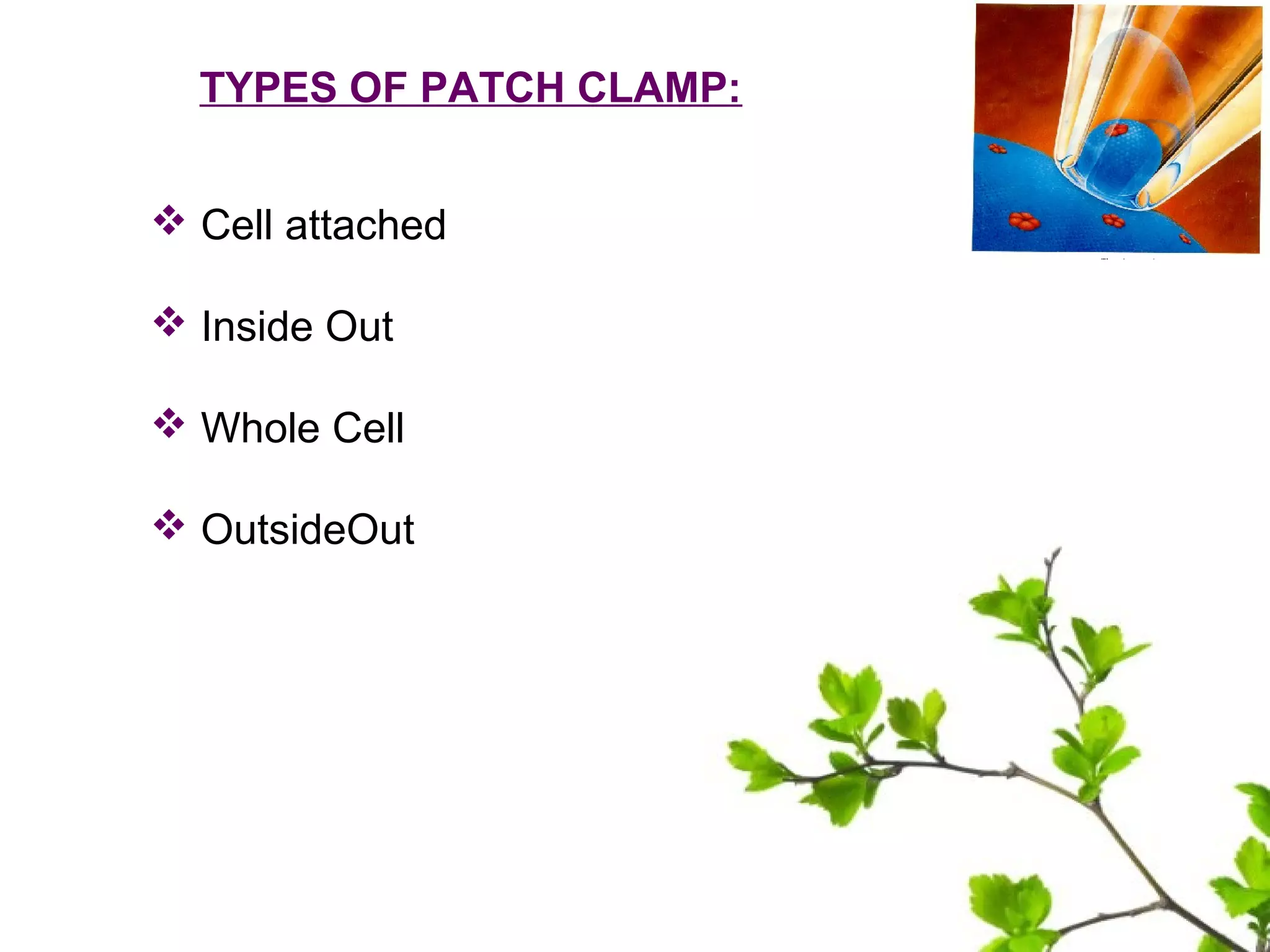


The document discusses the patch clamp technique, which allows the study of single or multiple ion channels in cells. It was developed in the late 1970s/early 1980s by Erwin Neher and Bert Sakmann, who received the Nobel Prize for this work. There are different configurations of patch clamp including cell-attached, whole-cell, outside-out, and inside-out. The technique involves pressing a glass pipette against a cell to form an electrical seal and record currents. It has applications in studying ion channels in excitable cells and the effects of drugs.
Introduction slide presenting the speaker's name, roll number, and institution.
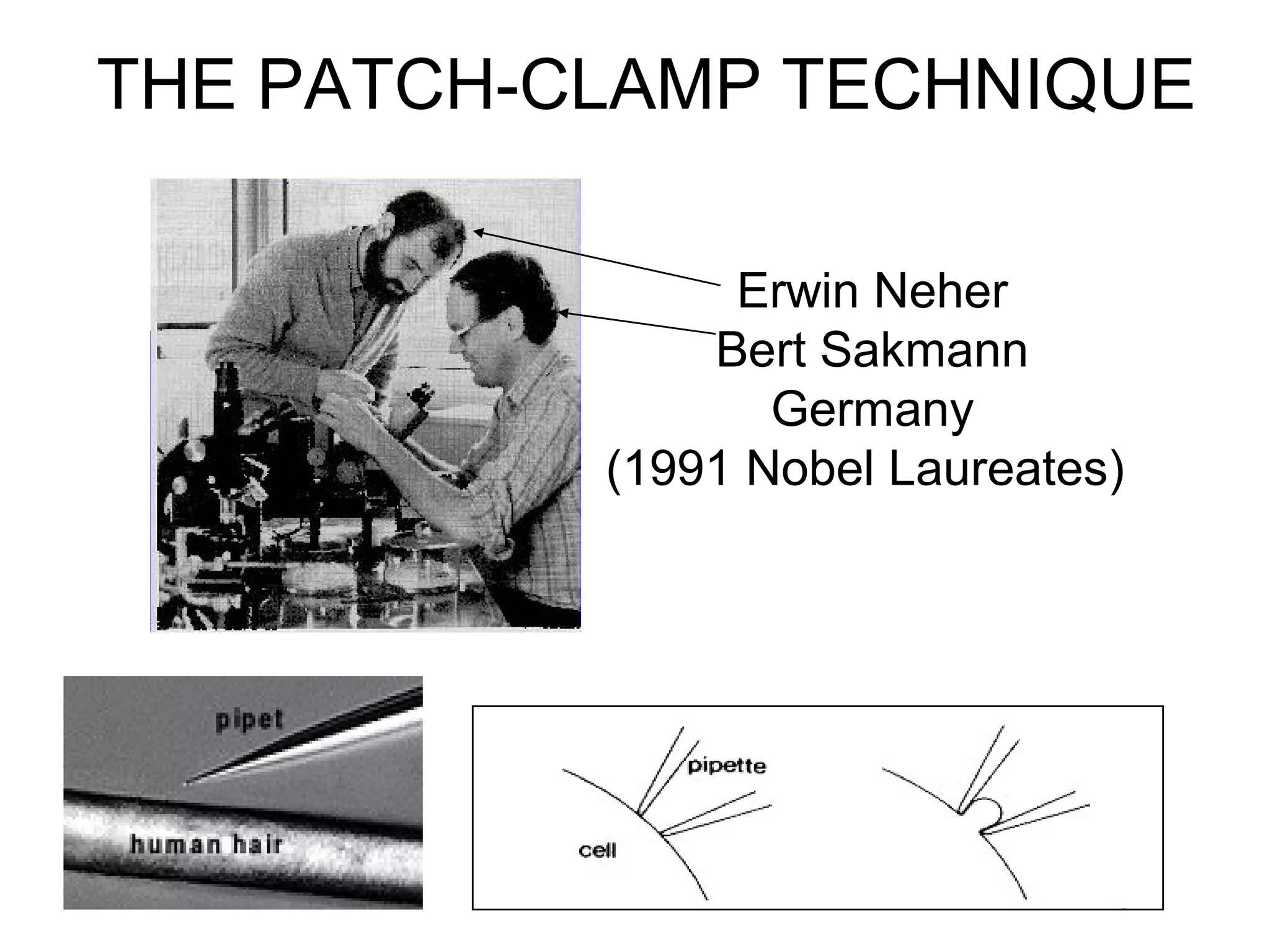
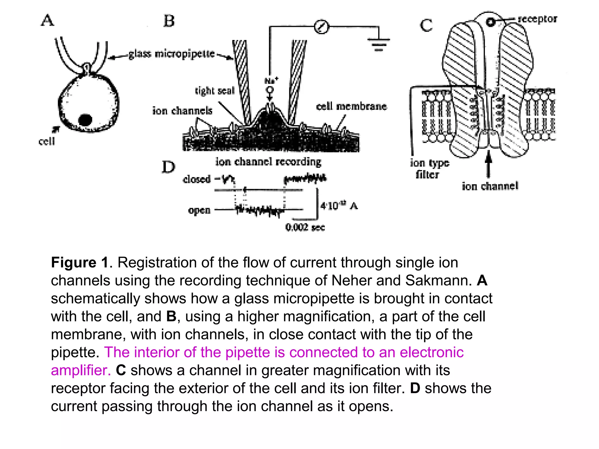
Overview of the patch clamp recording technique developed by Neher and Sakmann, used for studying ion channels.
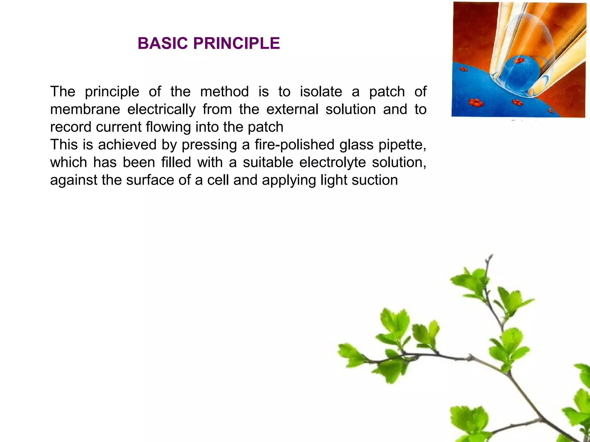
Describes the basic principle of isolating a membrane patch to record ion current using a pipette.
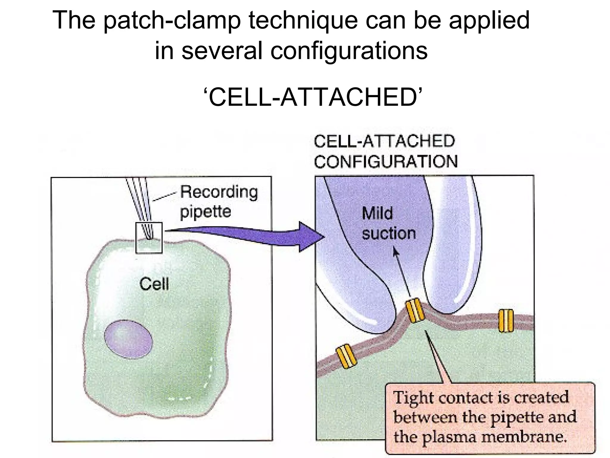
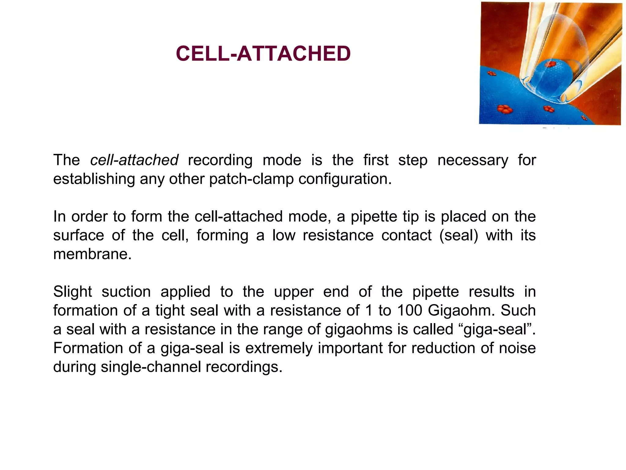
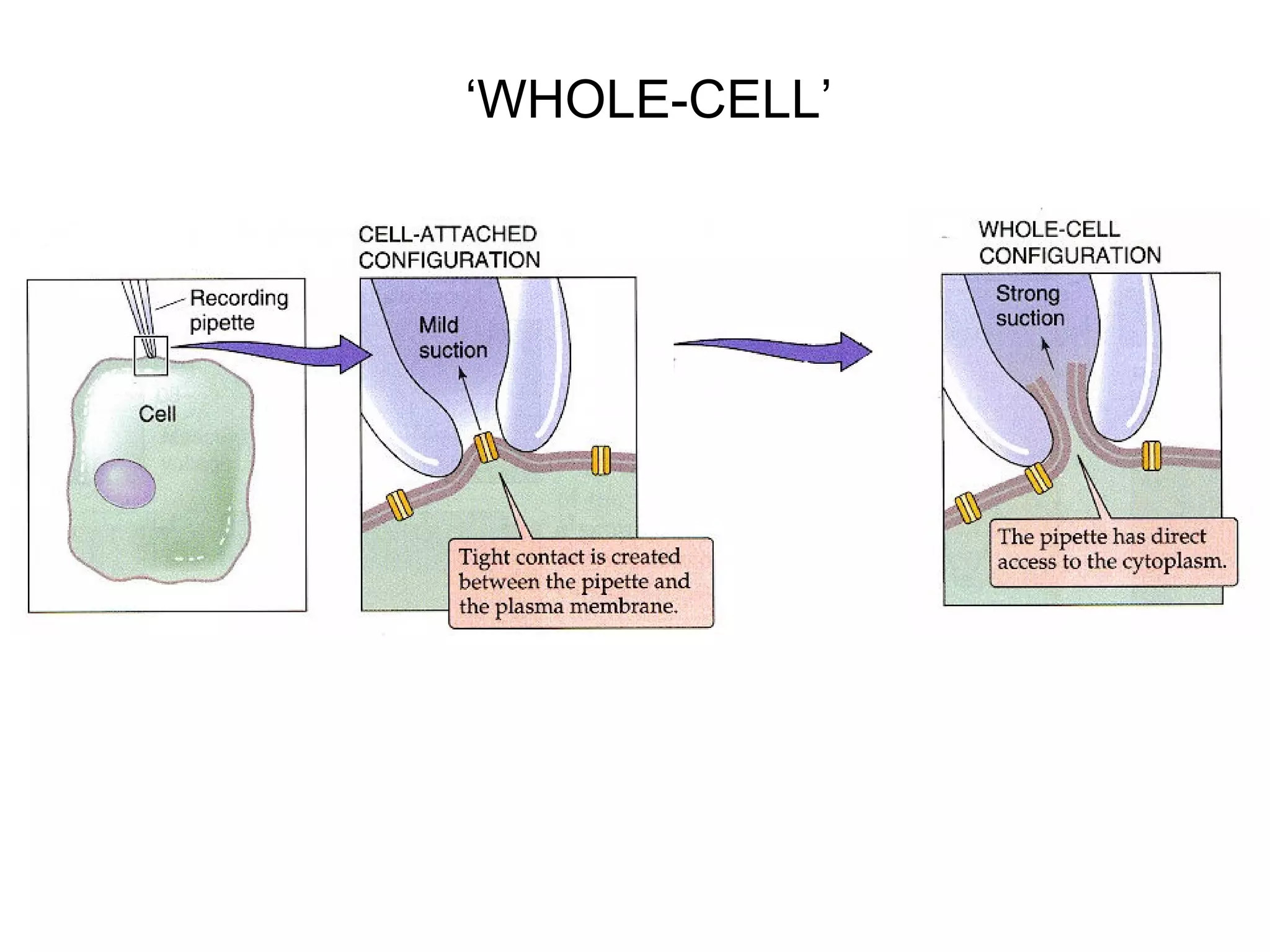
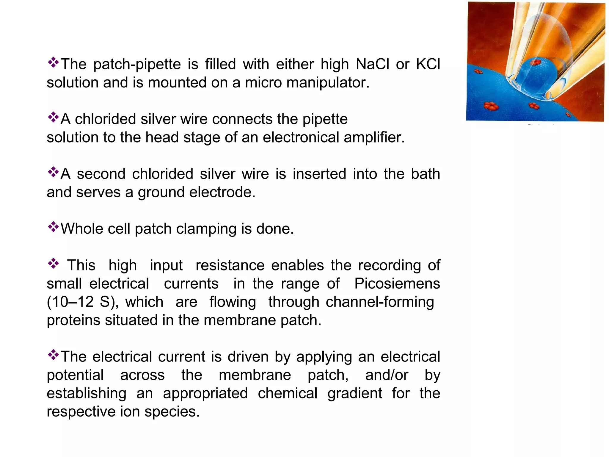
Explains cell-attached mode and its importance in establishing recordings with high resistance.
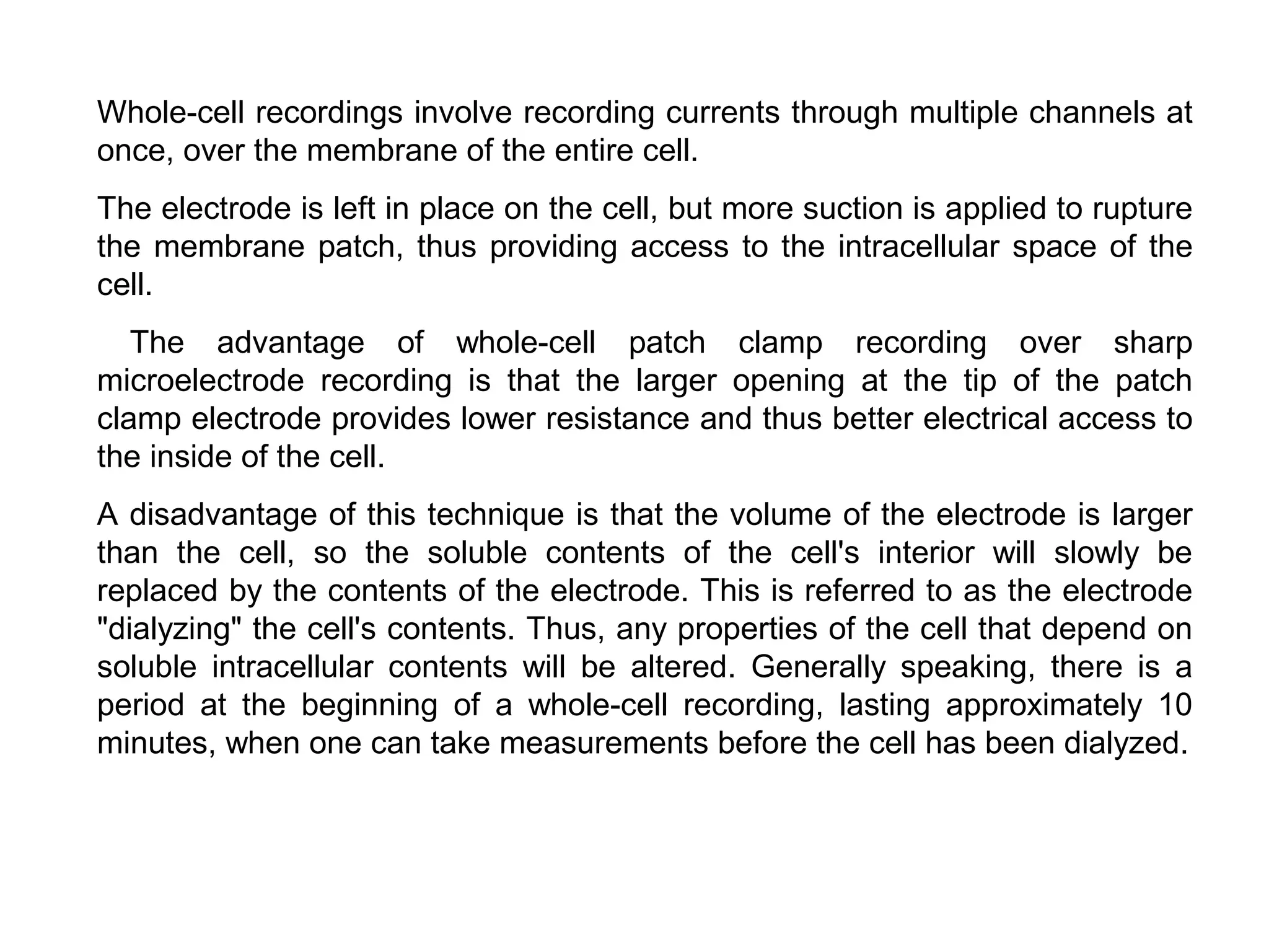
Describes whole-cell recordings, advantages, and disadvantages including effects on intracellular contents.
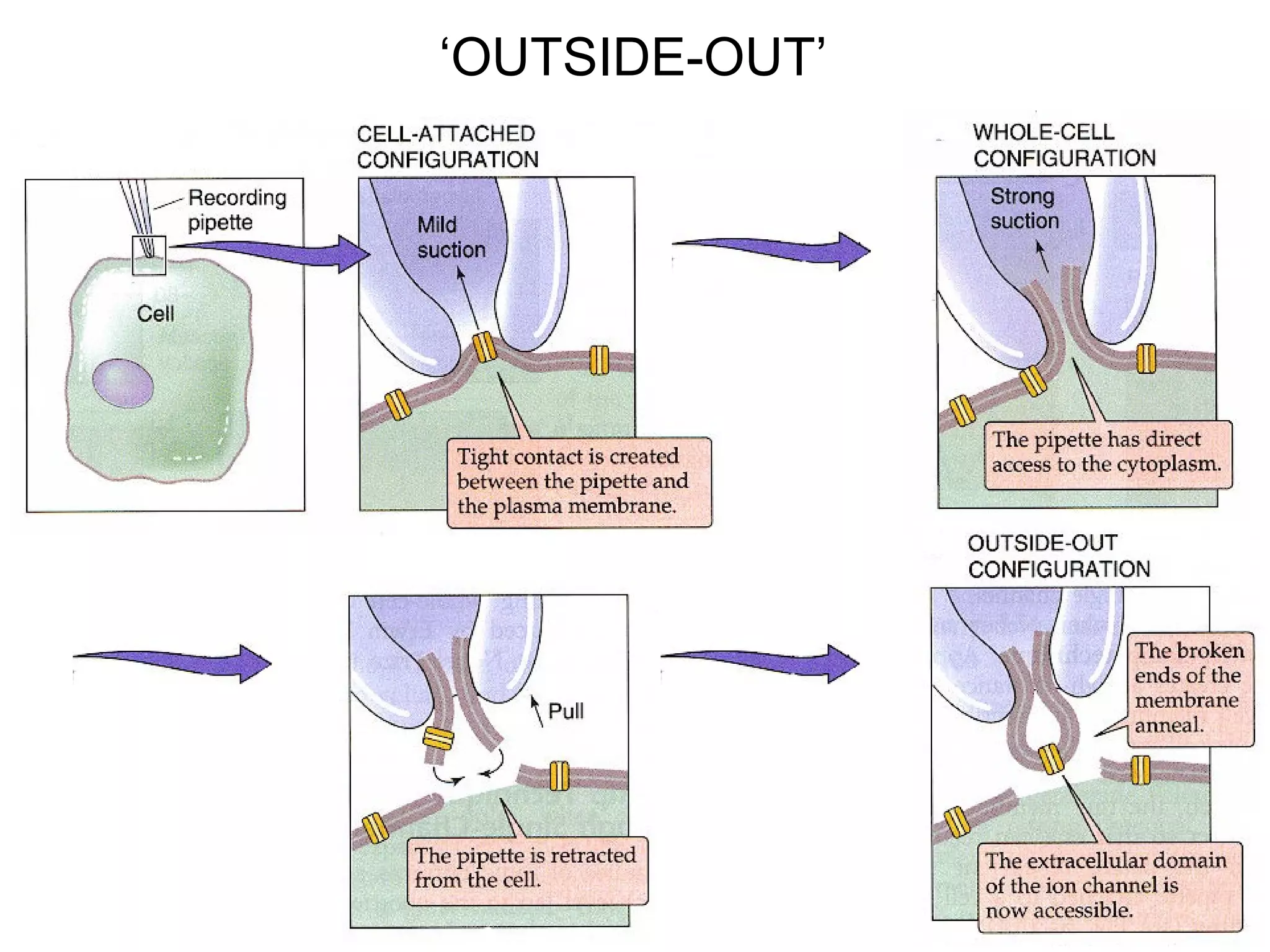
Details about the outside-out patch clamp technique and its benefits for studying ion channels.
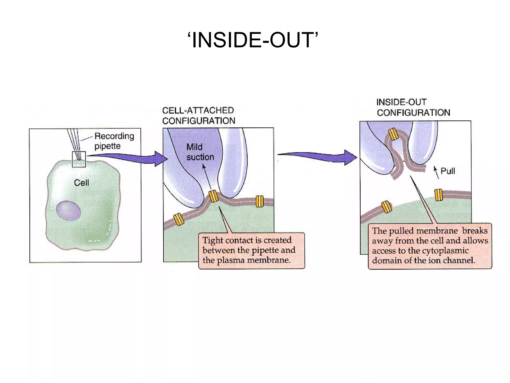
Explains the inside-out patch, exposing internal membrane environment for ion channel study.
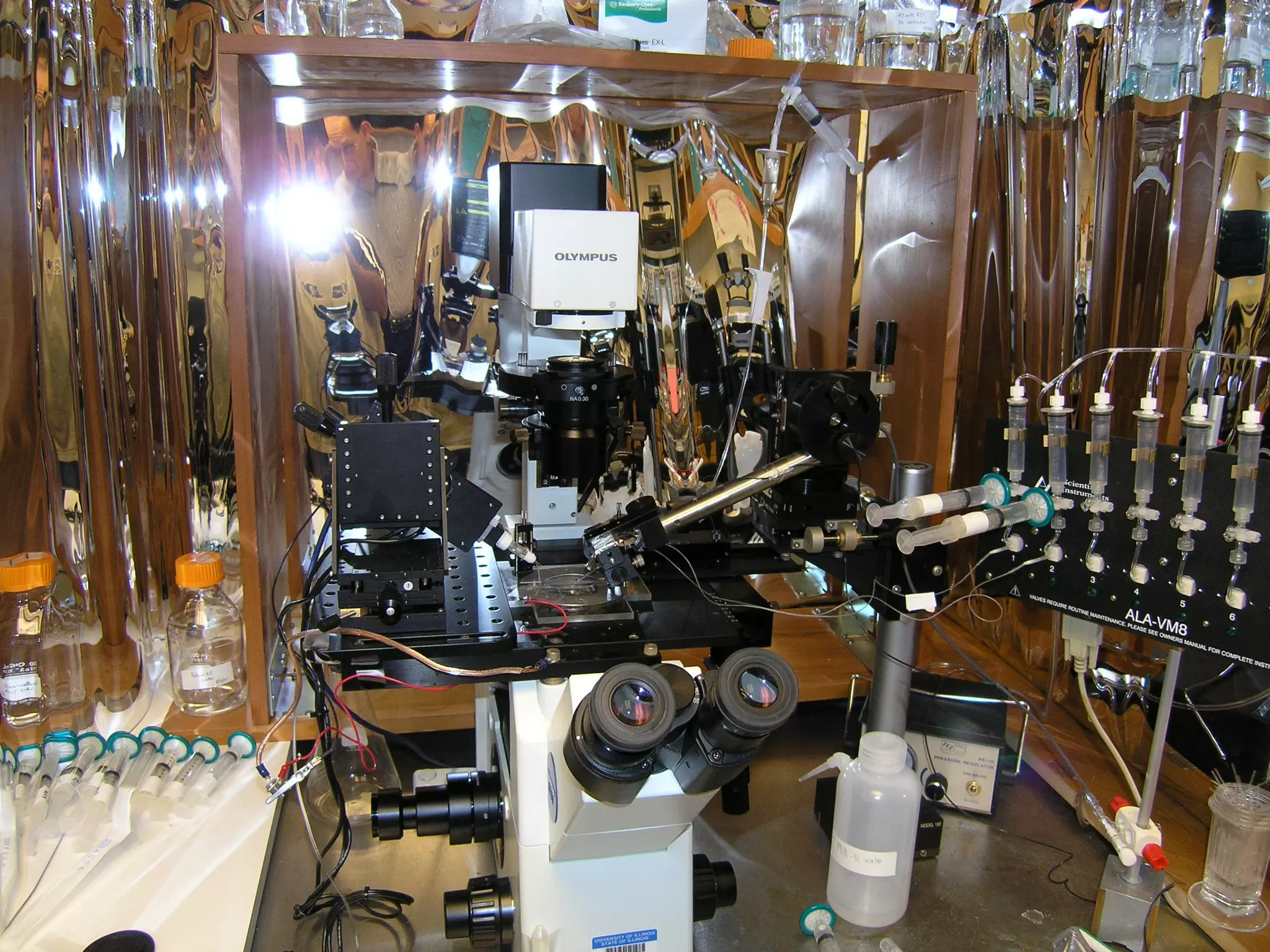
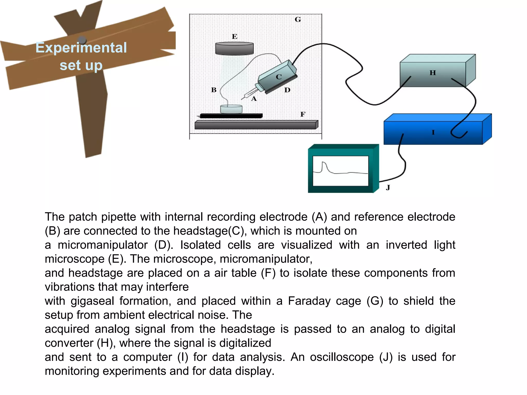
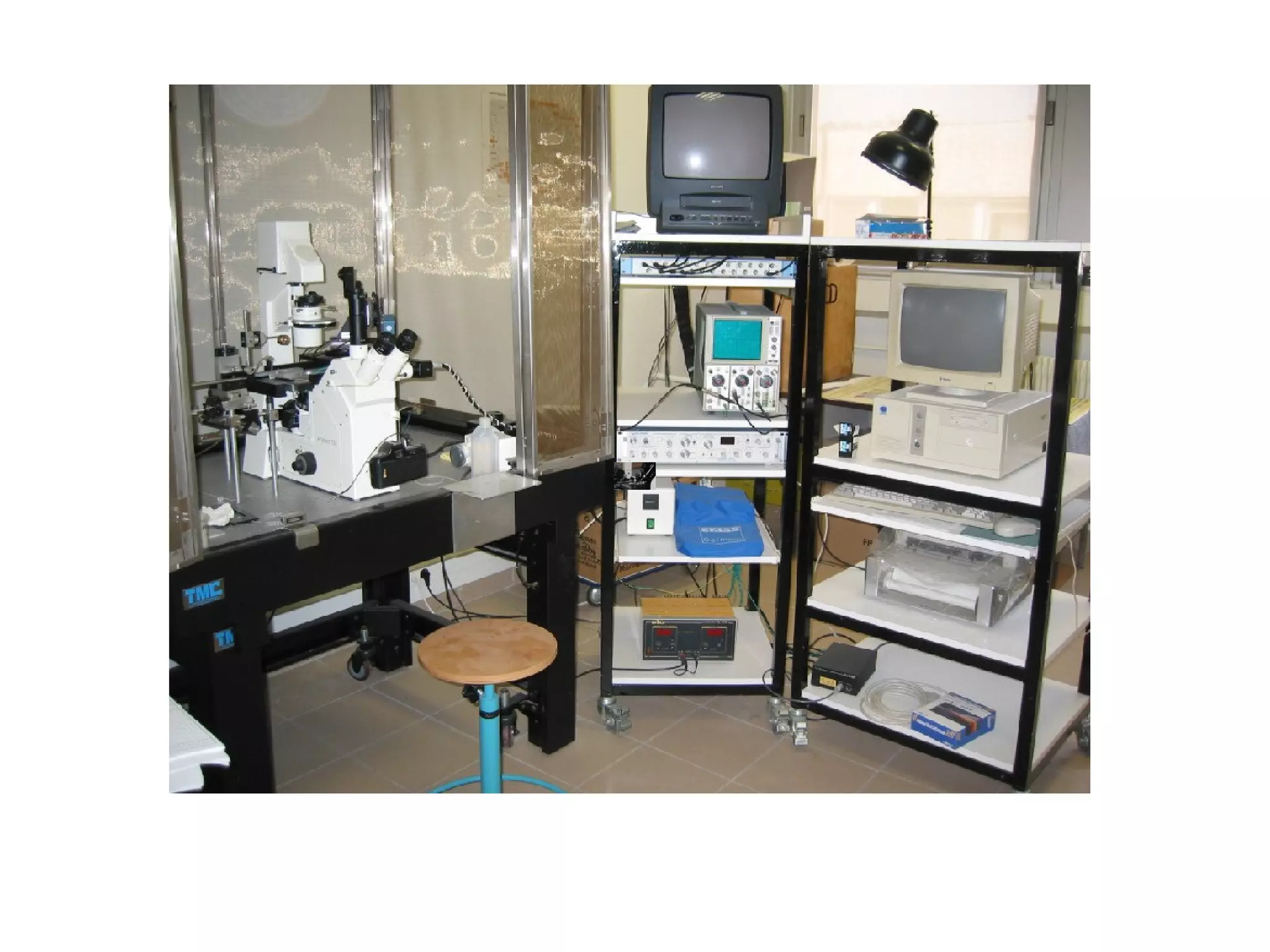
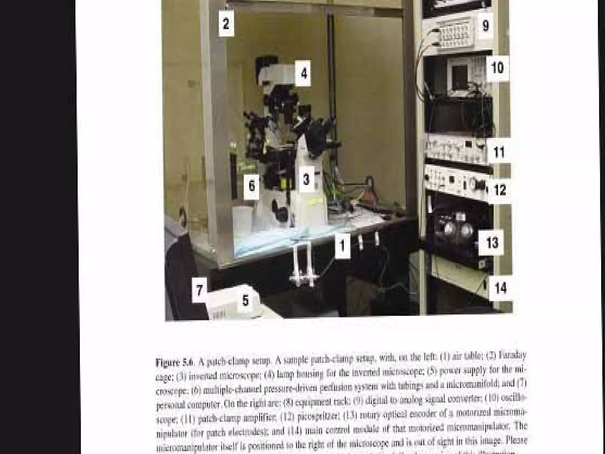
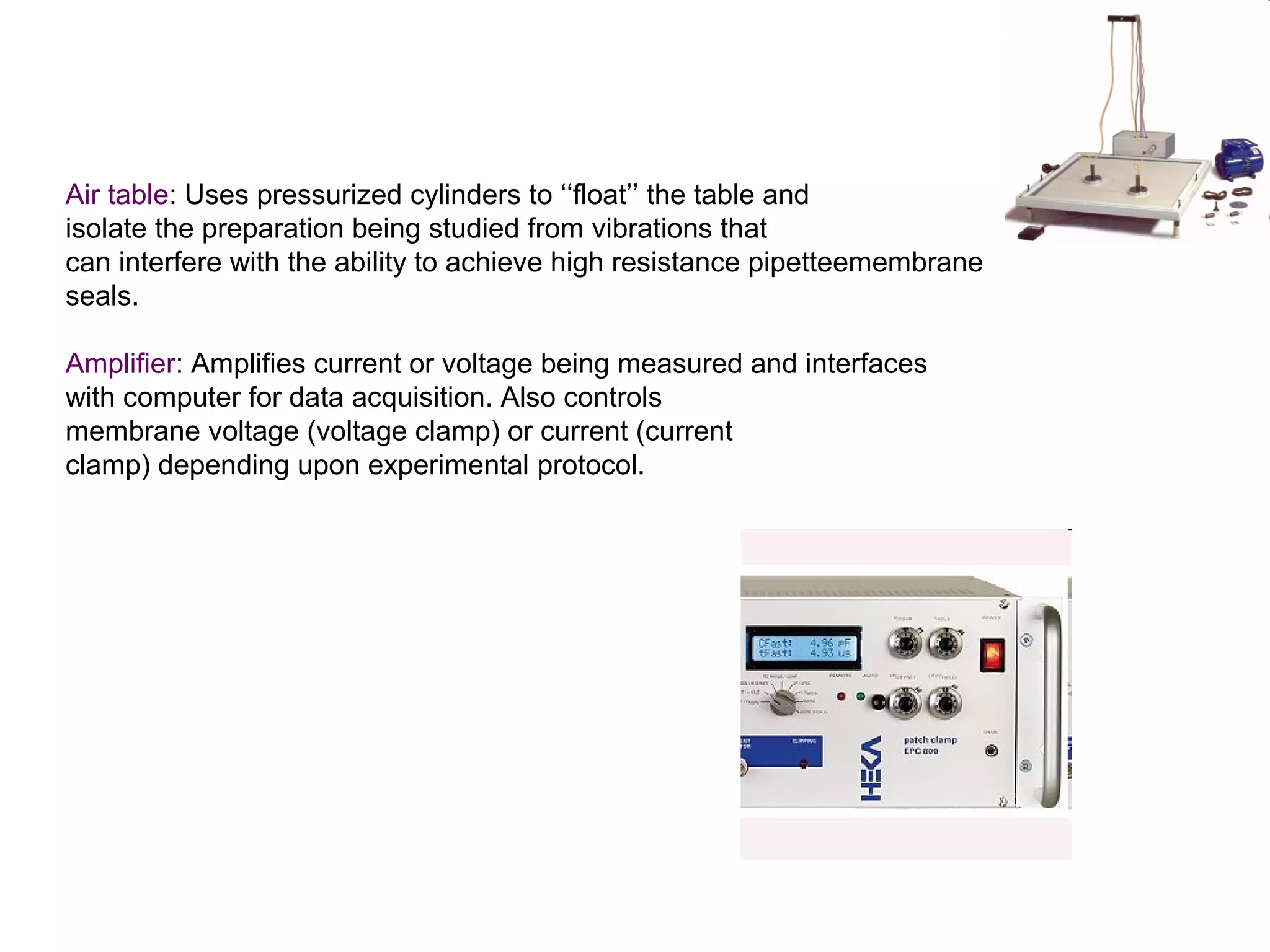
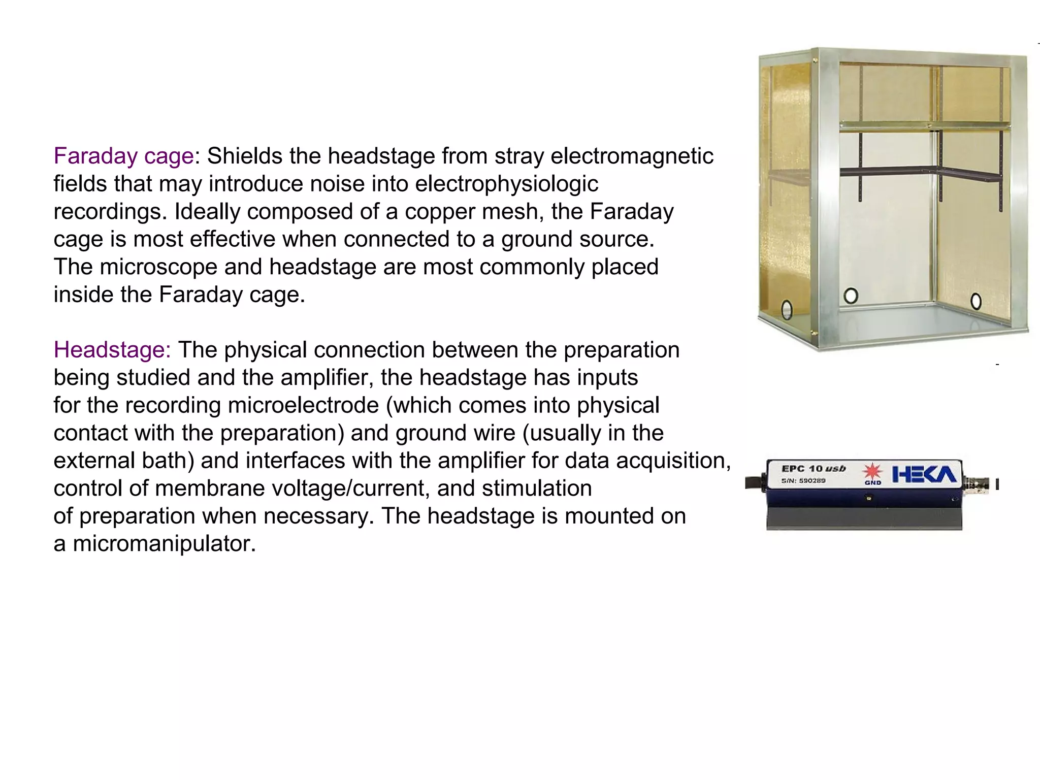
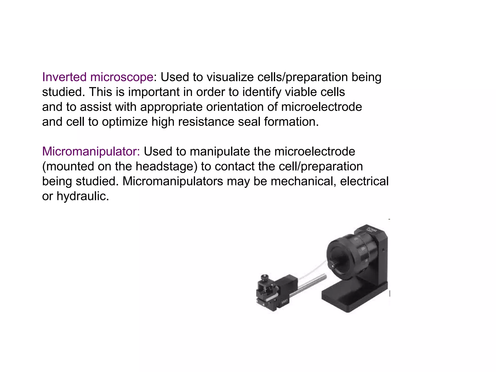
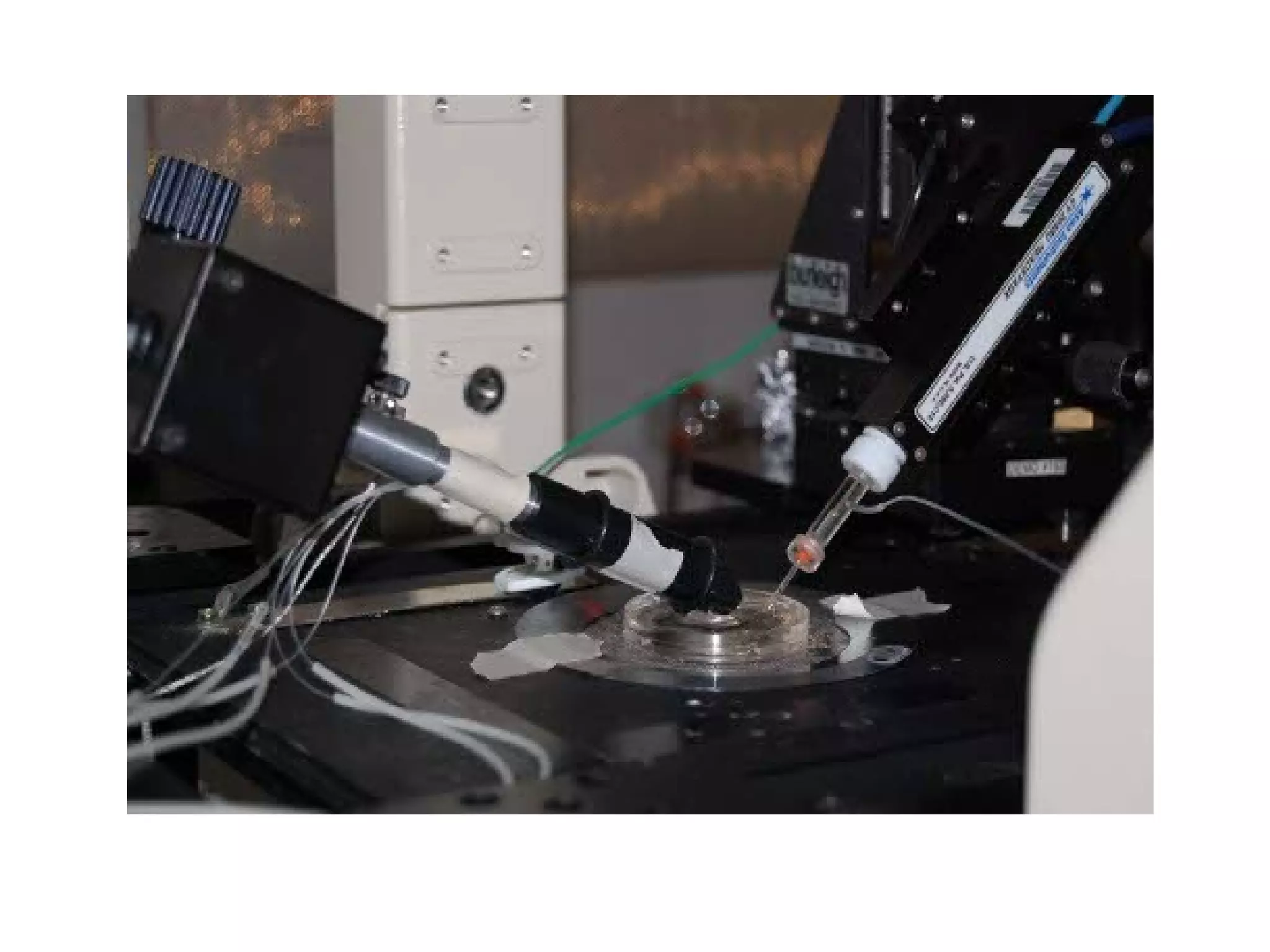
Describes experimental apparatus including air tables, amplifiers, and microscopes for patch clamp setup.
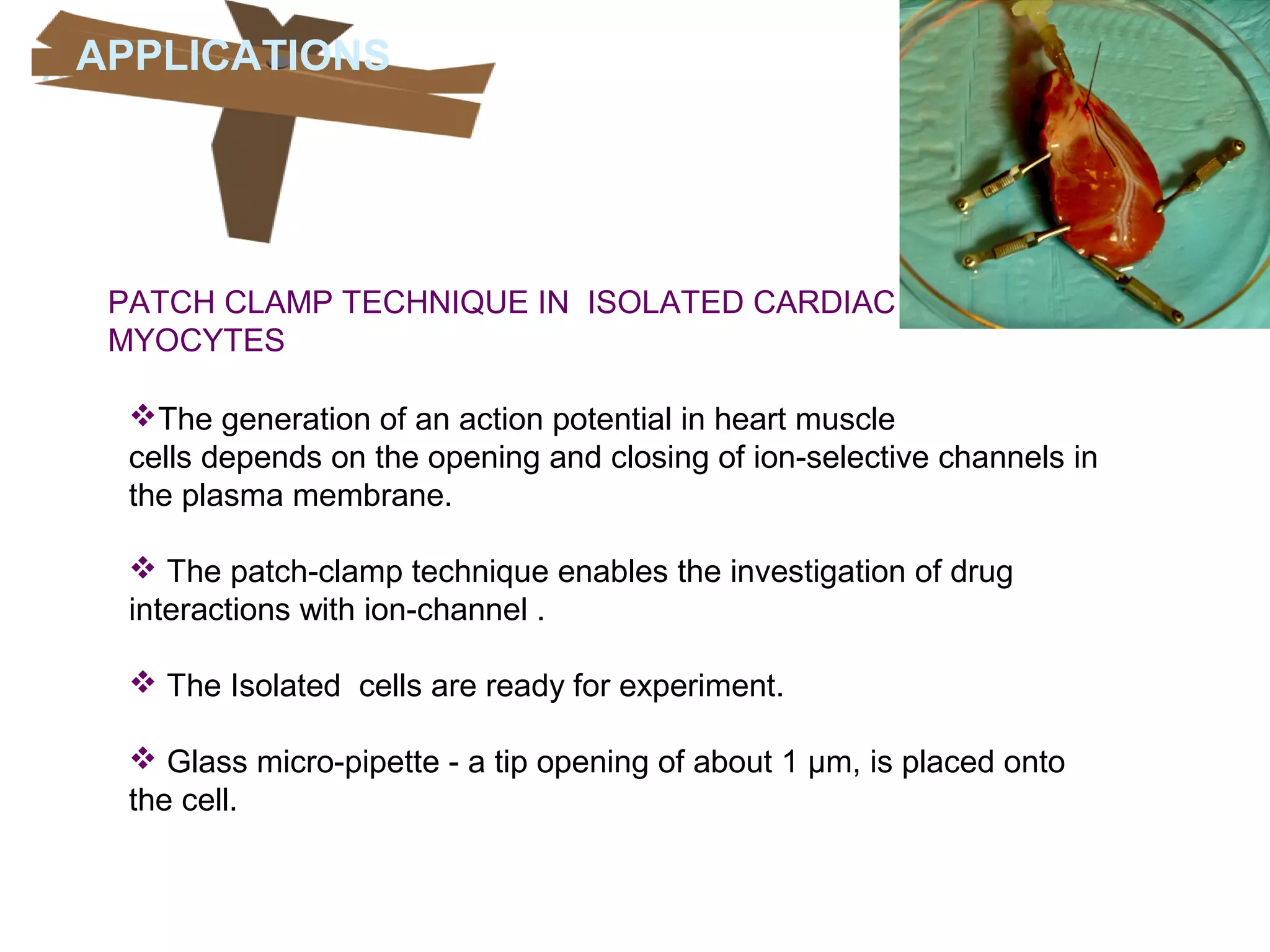
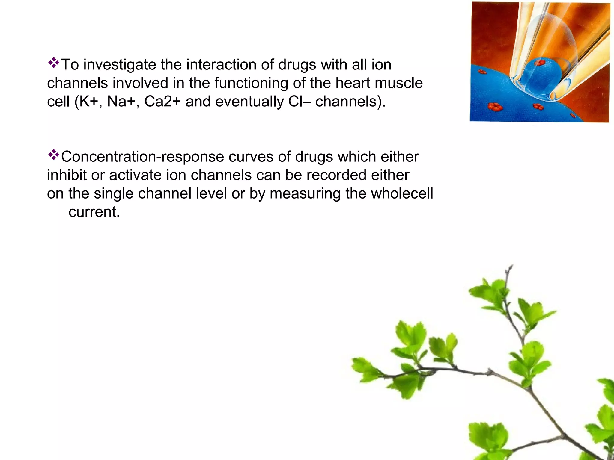
Application of patch clamp technique to isolated cardiac myocytes for studying ion channels and drug interactions.
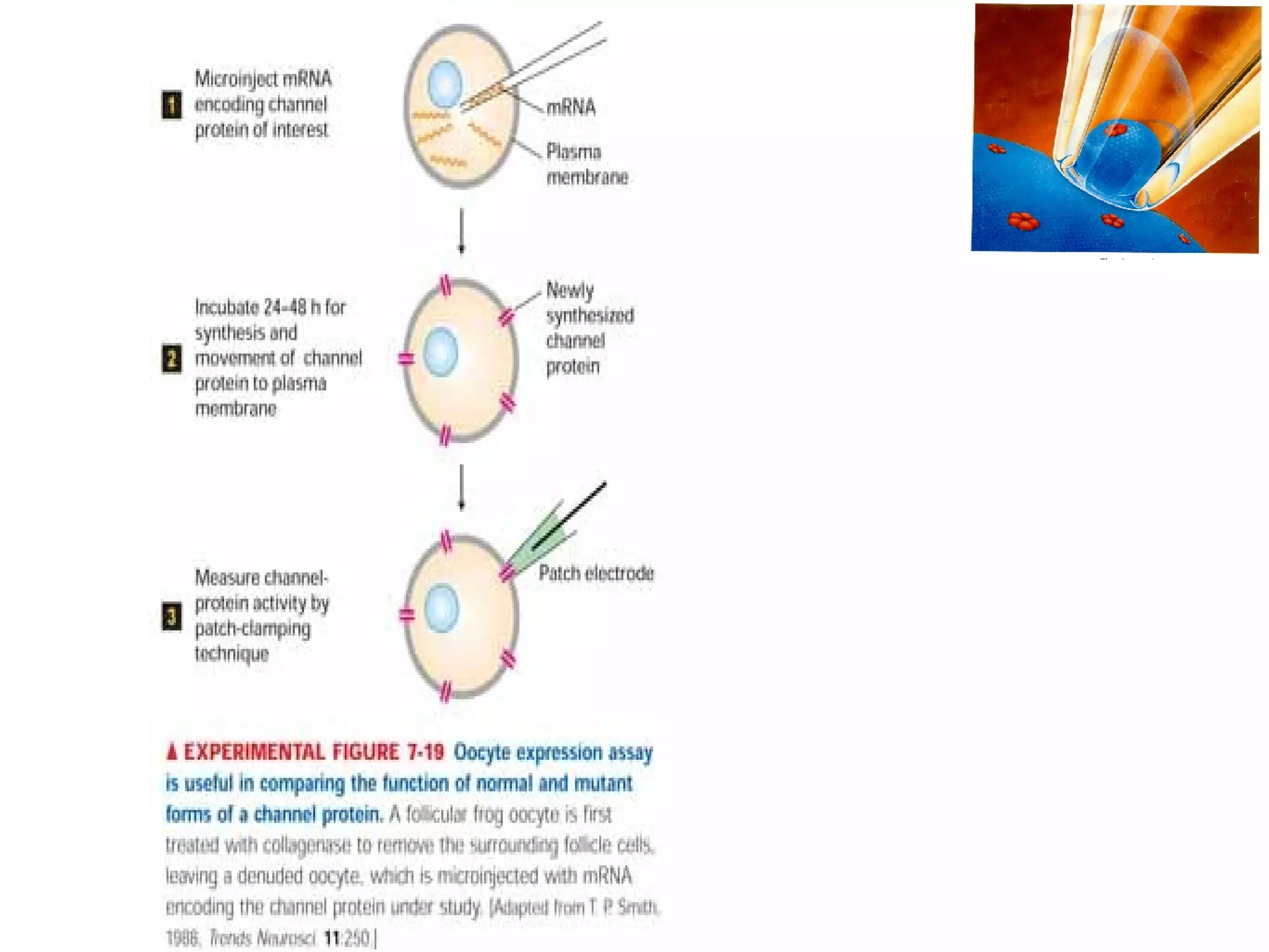
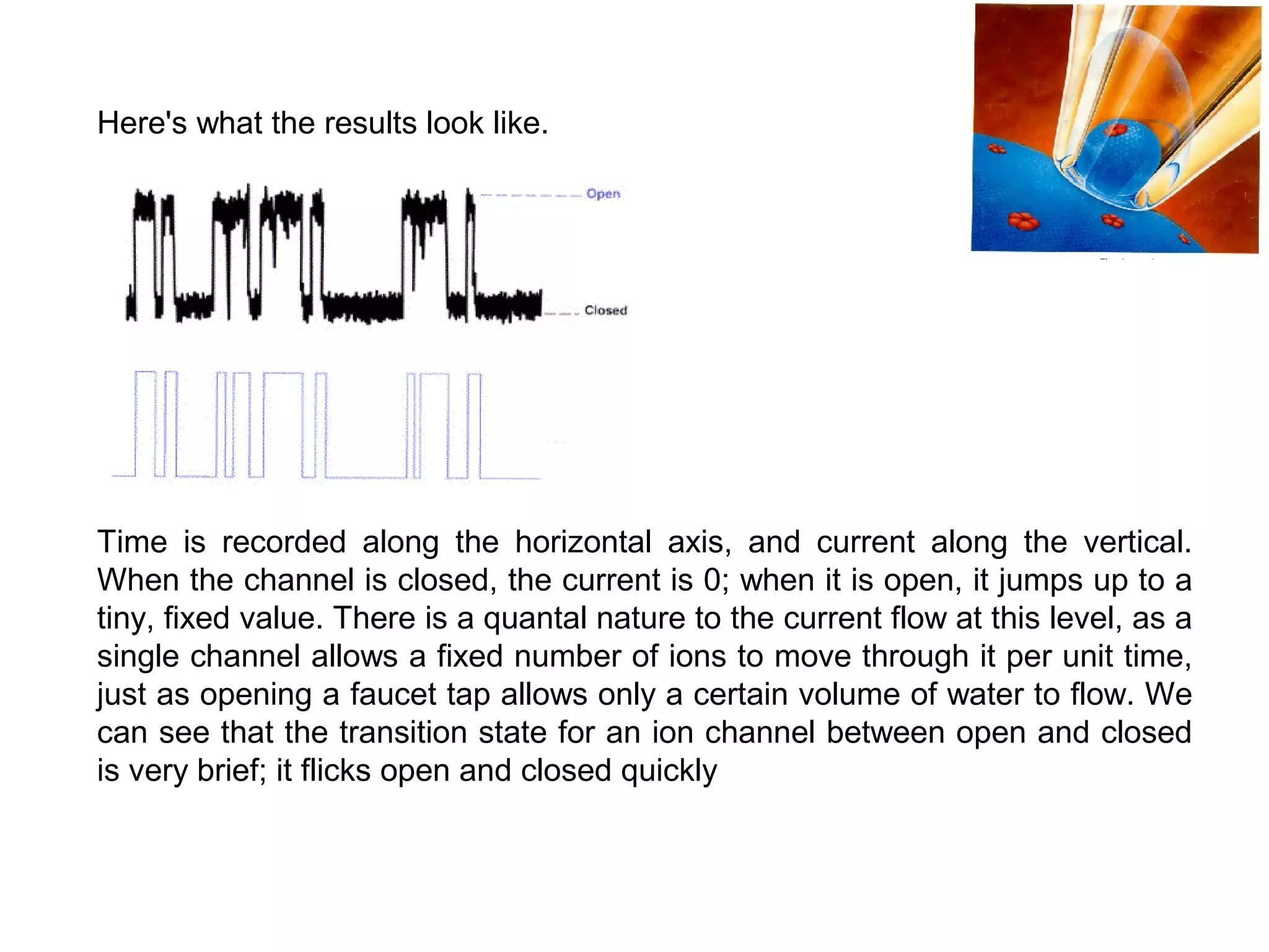
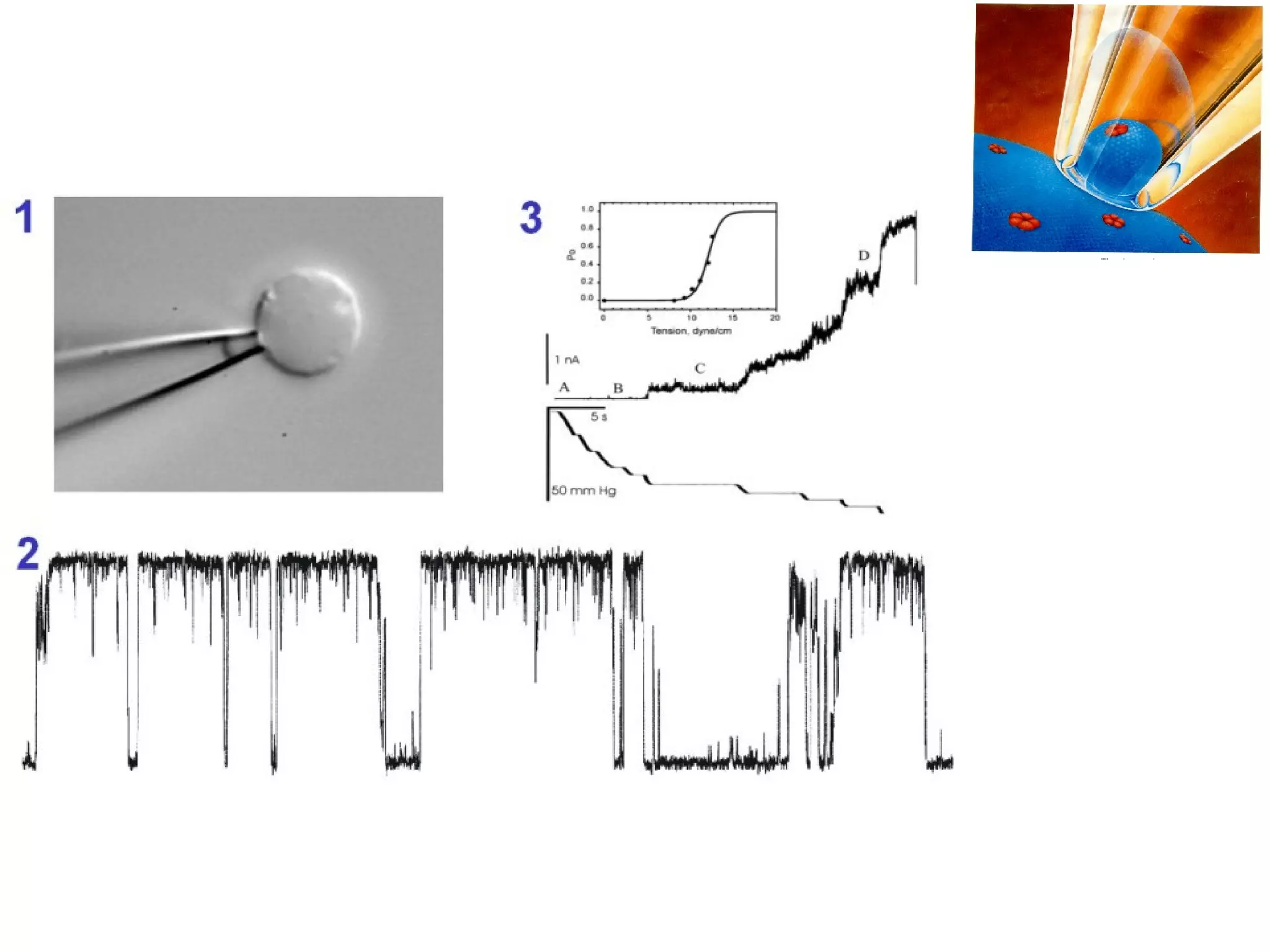
Describes novel ion channel characterization via oocyte expression and patch clamping, detailing experimental results.


