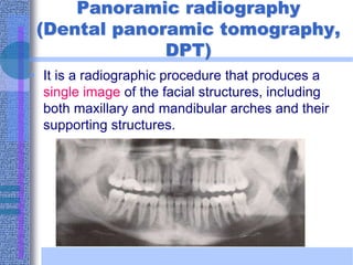
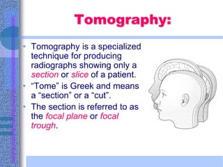
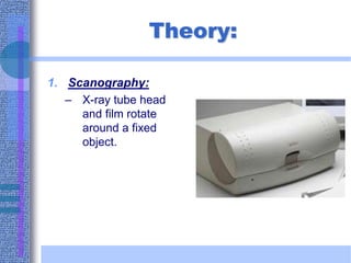
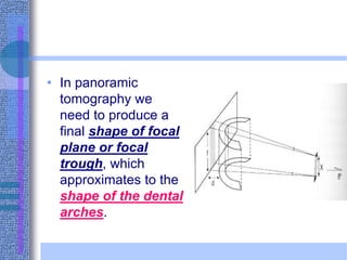
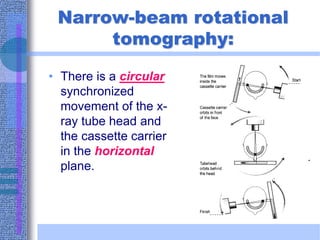
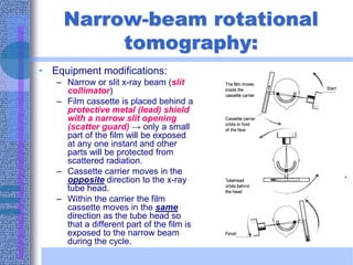
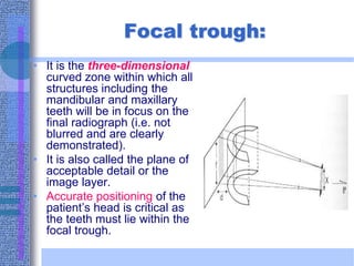
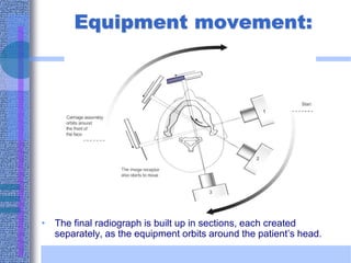
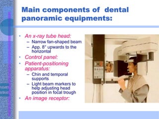
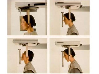
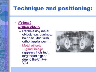
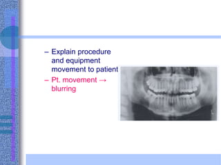
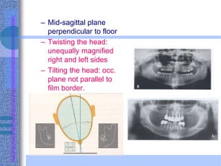
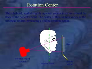
Panoramic radiography
(Dental panoramic tomography,
DPT)
• It is a radiographic procedure that produces a
single image of the facial structures, including
both maxillary and mandibular arches and their
supporting structures.
Tomography:
• Tomography is a specialized
technique for producing
radiographs showing only a
section or slice of a patient.
• “Tome” is Greek and means
a “section” or a “cut”.
• The section is referred to as
the focal plane or focal
trough.
Theory:
1. Scanography:
– X-ray tube head
and film rotate
around a fixed
object.
Theory:
2. Tomographic
movement:
– It requires controlled,
accurate movement of
both the x-ray tube
head and the film. They
are therefore linked
together.
• Objects at the centre of
rotation will appear in
focus, while others will
appear blurred or out of
focus.
• In panoramic
tomography we
need to produce a
final shape of focal
plane or focal
trough, which
approximates to the
shape of the dental
arches.
Narrow-beam rotational
tomography:
• There is a circular
synchronized
movement of the x-
ray tube head and
the cassette carrier
in the horizontal
plane.
Narrow-beam rotational
tomography:
• Equipment modifications:
– Narrow or slit x-ray beam (slit
collimator)
– Film cassette is placed behind a
protective metal (lead) shield
with a narrow slit opening
(scatter guard) → only a small
part of the film will be exposed
at any one instant and other
parts will be protected from
scattered radiation.
– Cassette carrier moves in the
opposite direction to the x-ray
tube head.
– Within the carrier the film
cassette moves in the same
direction as the tube head so
that a different part of the film is
exposed to the narrow beam
during the cycle.
Focal trough:
• It is the three-dimensional
curved zone within which all
structures including the
mandibular and maxillary
teeth will be in focus on the
final radiograph (i.e. not
blurred and are clearly
demonstrated).
• It is also called the plane of
acceptable detail or the
image layer.
• Accurate positioning of the
patient’s head is critical as
the teeth must lie within the
focal trough.
Equipment movement:
• The final radiograph is built up in sections, each created
separately, as the equipment orbits around the patient’s head.
Main components of dental
panoramic equipments:
• An x-ray tube head:
– Narrow fan-shaped beam
– App. 8° upwards to the
horizontal
• Control panel:
• Patient-positioning
apparatus:
– Chin and temporal
supports
– Light beam markers to
help adjusting head
position in focal trough
• An image receptor:
Cephalostat and bite positioning aid.
Cephalometric attachment.
Indications:
1. Overall view of the teeth and facial bones.
2. Assessment of the presence and the position of multiple unerupted
or impacted teeth.
3. Assessment of gross pathological lesions as cysts or tumours.
4. Radiography of both rami, condyles and coronoid processes and
assessment of any TMJ abnormalities.
5. It reveals fractures of the mandible from the midline to the neck of
the condyle.
6. It reveals the maxillary sinuses, floor of orbits and nasal bone.
7. It demonstrates the presence and progress of any periodontal
disease in an overall way.
8. It is valuable in orthodontics as it reveals the unerupted or absent
teeth and relation of mandible to maxilla.
9. Assessment of degree of alveolar bone and relationship of the
teeth to mental foramen, inferior dental canal and alveolar margin
before implantology.
Advantages:
1. Provides a large area of teeth and facial bones even when the
patient is unable to open his mouth.
2. It requires minimum cooperation of the patient and provides
minimum discomfort to him.
3. The time taken to carry out this technique is short compared to
a full mouth intraoral examination.
4. It is a simple and easy technique in comparison to intra-oral
techniques as positioning in panoramic radiography is relatively
simple with no films placed inside the mouth.
5. The radiation dosage is less than a full-mouth intra-oral
survey.
6. The image is easy for patients to understand, and is therefore a
good presentation for patients and a useful teaching aid.
7. The overall view of the jaws and both sides of mandible and
maxilla on one film is useful in comparing both sides and also
allows rapid assessment of any underlying possibly
unsuspected diseases.
Disadvantages and
limitations:
1. There is lack of definition due to the tomographic movement.
2. There is lack of detail and definition due to the increased object-film
distance and the use of the intensifying screens. This results in
image enlargement and magnification.
3. Due to superimposition of the spine, especially in short-necked
patients, there is always lack of clarity in the central portion of
the film (Ghost shadow appearance of the spine).
4. Patients with facial asymmetry or who do not conform to the shape
of the focal trough will not project a satisfactory image.
5. Soft tissues and air shadows can overlie the required hard tissue.
6. Interstitial caries and abnormalities of lamina dura can not be
diagnosed in most cases owing to the lack of fine detail and
sharpness.
7. The equipment is very expensive.
8. The technique is not suitable for children under five years
because of the relatively long exposure time.
Technique and positioning:
• Exact positioning
techniques vary from
one machine to
another. However
there are general
common requirements.
Technique and positioning:
• Patient
preparation:
– Remove any metal
objects e.g. earrings,
hair pins, dentures,
ortho. appliances,…
– Metal objects
→ghost image
(appears indistinct,
larger and higher
due to the 8° +ve
VA).
– Explain procedure
and equipment
movement to patient.
– Pt. movement →
blurring
– There is no need for
a lead apron
especially those with
a thyroid collar
– Thyroid collar will be
superimposed on the
ant. part of the jaw
• Patient
positioning:
– Patient should stand
or sit with the spine
straight.
– If spinal column is
not straight its
shadow will be
superimposed on the
symphyseal area of
the mandible
– Patient bites on the
bite-block with the
ant. teeth in an end
to end position in the
bite-block groove.
– Too far forward: ant.
Teeth appear blurred
and narrowed
– Too far back: ant.
teeth appear blurred
and widened
– Mid-sagittal plane
perpendicular to floor
– Twisting the head:
unequally magnified
right and left sides
– Tilting the head: occ.
plane not parallel to
film border.
– Position Frankfort
plane parallel to the
floor.
– chin too high:
• Flat occ. plane or
reverse smile line
• Hard palate
superimposed on
maxillary roots
– Chin too low:
excessive smile line
• Close lips, press
tongue against
palate, don’t
swallow and hold
your breath to
prevent RL shadow
of airspaces.
intraoral
collimation
panoramic
collimation
Collimation
In order to limit the exposure to the patient, the x-ray beam is
collimated. The collimator controls the size and shape of the x-
ray beam. Intraorally, the x-ray beam is either round or
rectangular and is large enough to cover the entire intraoral film.
The collimator for panoramic radiography produces a narrow,
rectangular x-ray beam that exposes a small portion of the film
as the tubehead and film rotate around the patient.
rotation center
film
tubehead angled
upward
Rotation Center
The tubehead, angled slightly upward, rotates in an arc around the
back of the patient’s head. The center of this rotation varies as the
tubehead rotates, producing a sliding rotation center.
cassette
shield
cassette shield with
narrow vertical slit
tubehead
rotation
film/cassette
rotation
Tubehead Rotation
As the tubehead rotates around the
patient, the cassette holder is also
rotating so that it is always lined up
with the x-ray beam. The x-ray
beam passes through a narrow
vertical opening in the cassette
shield, which allows only a small
portion of the film to be exposed at
a time. The film/cassette rotates
within this shield, constantly
exposing different parts of the film
as the whole unit rotates.
cassette shield with
narrow vertical slit
(see below)
As the tubehead rotates around the patient, the x-ray beam passes
through different parts of the jaws, producing multiple images that
appear as one continuous image on the film (“panoramic view”).
When you click the mouse, the tubehead will rotate around the
patient and produce the images. The red dots represent the sliding
rotation center.
Click the mouse to align and merge these individual images into
one continuous image.
The film above shows the left side of the patient on the left.
We normally look at the film as if we were facing the patient,
so that the patient’s right side is on our left. Click the mouse to
rotate the film into the correct orientation for viewing .
posterior rotation center
(image right side)
anterior rotation center
(image anterior teeth)
path of sliding
rotation center
posterior rotation center
(image left side)
Sliding Rotation Center
L R
At the starting point, with the tubehead on the patient’s left, the
rotation center is located posteriorly, on the same side as the
tubehead, as shown below. As the tubehead moves behind the
patient, the rotation center “slides” toward the front. As the
tubehead continues to move to the patient’s right, the rotation
center “slides” back posteriorly.
x-rays

Panoramic Radiography

  • 1.
  • 2.
    Panoramic radiography (Dental panoramictomography, DPT) • It is a radiographic procedure that produces a single image of the facial structures, including both maxillary and mandibular arches and their supporting structures.
  • 3.
    Tomography: • Tomography isa specialized technique for producing radiographs showing only a section or slice of a patient. • “Tome” is Greek and means a “section” or a “cut”. • The section is referred to as the focal plane or focal trough.
  • 4.
    Theory: 1. Scanography: – X-raytube head and film rotate around a fixed object.
  • 5.
    Theory: 2. Tomographic movement: – Itrequires controlled, accurate movement of both the x-ray tube head and the film. They are therefore linked together. • Objects at the centre of rotation will appear in focus, while others will appear blurred or out of focus.
  • 6.
    • In panoramic tomographywe need to produce a final shape of focal plane or focal trough, which approximates to the shape of the dental arches.
  • 7.
    Narrow-beam rotational tomography: • Thereis a circular synchronized movement of the x- ray tube head and the cassette carrier in the horizontal plane.
  • 8.
    Narrow-beam rotational tomography: • Equipmentmodifications: – Narrow or slit x-ray beam (slit collimator) – Film cassette is placed behind a protective metal (lead) shield with a narrow slit opening (scatter guard) → only a small part of the film will be exposed at any one instant and other parts will be protected from scattered radiation. – Cassette carrier moves in the opposite direction to the x-ray tube head. – Within the carrier the film cassette moves in the same direction as the tube head so that a different part of the film is exposed to the narrow beam during the cycle.
  • 9.
    Focal trough: • Itis the three-dimensional curved zone within which all structures including the mandibular and maxillary teeth will be in focus on the final radiograph (i.e. not blurred and are clearly demonstrated). • It is also called the plane of acceptable detail or the image layer. • Accurate positioning of the patient’s head is critical as the teeth must lie within the focal trough.
  • 10.
    Equipment movement: • Thefinal radiograph is built up in sections, each created separately, as the equipment orbits around the patient’s head.
  • 11.
    Main components ofdental panoramic equipments: • An x-ray tube head: – Narrow fan-shaped beam – App. 8° upwards to the horizontal • Control panel: • Patient-positioning apparatus: – Chin and temporal supports – Light beam markers to help adjusting head position in focal trough • An image receptor:
  • 13.
    Cephalostat and bitepositioning aid. Cephalometric attachment.
  • 15.
    Indications: 1. Overall viewof the teeth and facial bones. 2. Assessment of the presence and the position of multiple unerupted or impacted teeth. 3. Assessment of gross pathological lesions as cysts or tumours. 4. Radiography of both rami, condyles and coronoid processes and assessment of any TMJ abnormalities. 5. It reveals fractures of the mandible from the midline to the neck of the condyle. 6. It reveals the maxillary sinuses, floor of orbits and nasal bone. 7. It demonstrates the presence and progress of any periodontal disease in an overall way. 8. It is valuable in orthodontics as it reveals the unerupted or absent teeth and relation of mandible to maxilla. 9. Assessment of degree of alveolar bone and relationship of the teeth to mental foramen, inferior dental canal and alveolar margin before implantology.
  • 18.
    Advantages: 1. Provides alarge area of teeth and facial bones even when the patient is unable to open his mouth. 2. It requires minimum cooperation of the patient and provides minimum discomfort to him. 3. The time taken to carry out this technique is short compared to a full mouth intraoral examination. 4. It is a simple and easy technique in comparison to intra-oral techniques as positioning in panoramic radiography is relatively simple with no films placed inside the mouth. 5. The radiation dosage is less than a full-mouth intra-oral survey. 6. The image is easy for patients to understand, and is therefore a good presentation for patients and a useful teaching aid. 7. The overall view of the jaws and both sides of mandible and maxilla on one film is useful in comparing both sides and also allows rapid assessment of any underlying possibly unsuspected diseases.
  • 19.
    Disadvantages and limitations: 1. Thereis lack of definition due to the tomographic movement. 2. There is lack of detail and definition due to the increased object-film distance and the use of the intensifying screens. This results in image enlargement and magnification. 3. Due to superimposition of the spine, especially in short-necked patients, there is always lack of clarity in the central portion of the film (Ghost shadow appearance of the spine). 4. Patients with facial asymmetry or who do not conform to the shape of the focal trough will not project a satisfactory image. 5. Soft tissues and air shadows can overlie the required hard tissue. 6. Interstitial caries and abnormalities of lamina dura can not be diagnosed in most cases owing to the lack of fine detail and sharpness. 7. The equipment is very expensive. 8. The technique is not suitable for children under five years because of the relatively long exposure time.
  • 20.
    Technique and positioning: •Exact positioning techniques vary from one machine to another. However there are general common requirements.
  • 21.
    Technique and positioning: •Patient preparation: – Remove any metal objects e.g. earrings, hair pins, dentures, ortho. appliances,… – Metal objects →ghost image (appears indistinct, larger and higher due to the 8° +ve VA).
  • 22.
    – Explain procedure andequipment movement to patient. – Pt. movement → blurring
  • 23.
    – There isno need for a lead apron especially those with a thyroid collar – Thyroid collar will be superimposed on the ant. part of the jaw
  • 24.
    • Patient positioning: – Patientshould stand or sit with the spine straight. – If spinal column is not straight its shadow will be superimposed on the symphyseal area of the mandible
  • 25.
    – Patient biteson the bite-block with the ant. teeth in an end to end position in the bite-block groove.
  • 26.
    – Too farforward: ant. Teeth appear blurred and narrowed
  • 27.
    – Too farback: ant. teeth appear blurred and widened
  • 28.
    – Mid-sagittal plane perpendicularto floor – Twisting the head: unequally magnified right and left sides – Tilting the head: occ. plane not parallel to film border.
  • 29.
    – Position Frankfort planeparallel to the floor. – chin too high: • Flat occ. plane or reverse smile line • Hard palate superimposed on maxillary roots
  • 30.
    – Chin toolow: excessive smile line
  • 31.
    • Close lips,press tongue against palate, don’t swallow and hold your breath to prevent RL shadow of airspaces.
  • 32.
    intraoral collimation panoramic collimation Collimation In order tolimit the exposure to the patient, the x-ray beam is collimated. The collimator controls the size and shape of the x- ray beam. Intraorally, the x-ray beam is either round or rectangular and is large enough to cover the entire intraoral film. The collimator for panoramic radiography produces a narrow, rectangular x-ray beam that exposes a small portion of the film as the tubehead and film rotate around the patient.
  • 33.
    rotation center film tubehead angled upward RotationCenter The tubehead, angled slightly upward, rotates in an arc around the back of the patient’s head. The center of this rotation varies as the tubehead rotates, producing a sliding rotation center. cassette shield
  • 34.
    cassette shield with narrowvertical slit tubehead rotation film/cassette rotation Tubehead Rotation As the tubehead rotates around the patient, the cassette holder is also rotating so that it is always lined up with the x-ray beam. The x-ray beam passes through a narrow vertical opening in the cassette shield, which allows only a small portion of the film to be exposed at a time. The film/cassette rotates within this shield, constantly exposing different parts of the film as the whole unit rotates. cassette shield with narrow vertical slit (see below)
  • 35.
    As the tubeheadrotates around the patient, the x-ray beam passes through different parts of the jaws, producing multiple images that appear as one continuous image on the film (“panoramic view”). When you click the mouse, the tubehead will rotate around the patient and produce the images. The red dots represent the sliding rotation center. Click the mouse to align and merge these individual images into one continuous image. The film above shows the left side of the patient on the left. We normally look at the film as if we were facing the patient, so that the patient’s right side is on our left. Click the mouse to rotate the film into the correct orientation for viewing .
  • 36.
    posterior rotation center (imageright side) anterior rotation center (image anterior teeth) path of sliding rotation center posterior rotation center (image left side) Sliding Rotation Center L R At the starting point, with the tubehead on the patient’s left, the rotation center is located posteriorly, on the same side as the tubehead, as shown below. As the tubehead moves behind the patient, the rotation center “slides” toward the front. As the tubehead continues to move to the patient’s right, the rotation center “slides” back posteriorly. x-rays