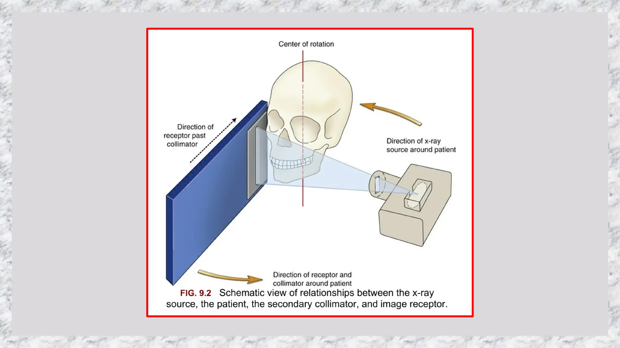
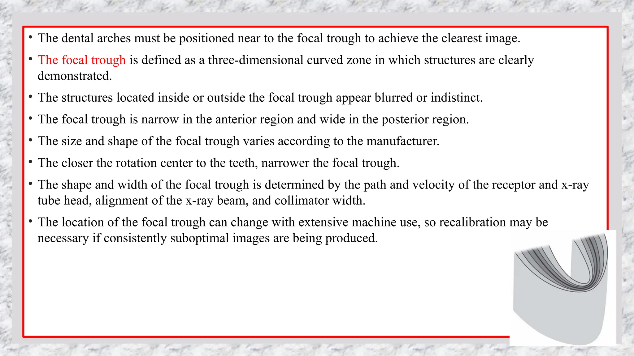
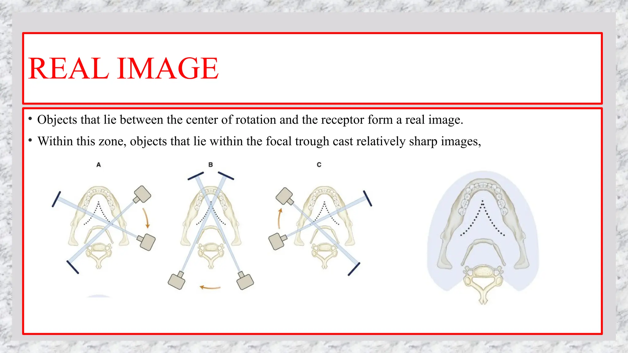
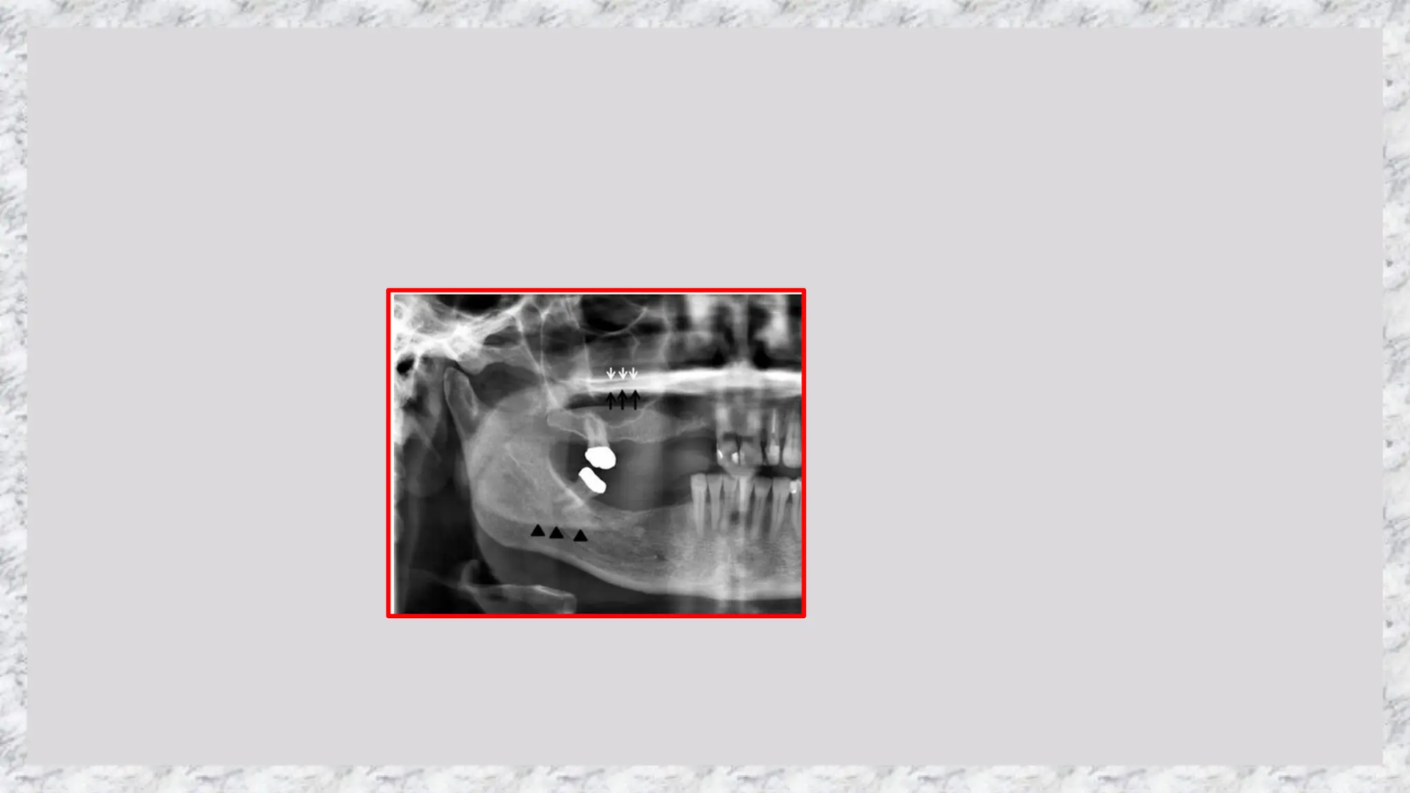
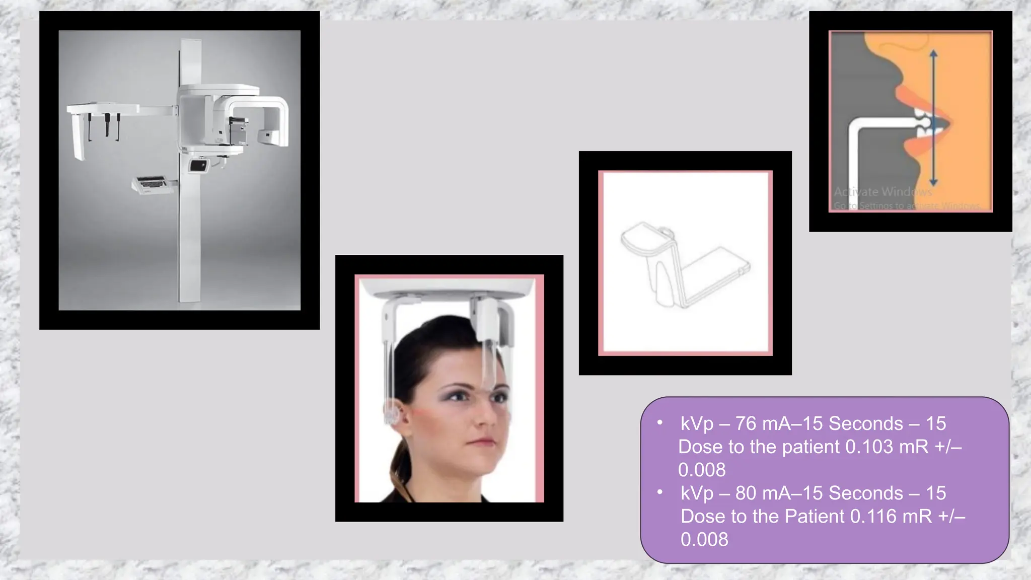
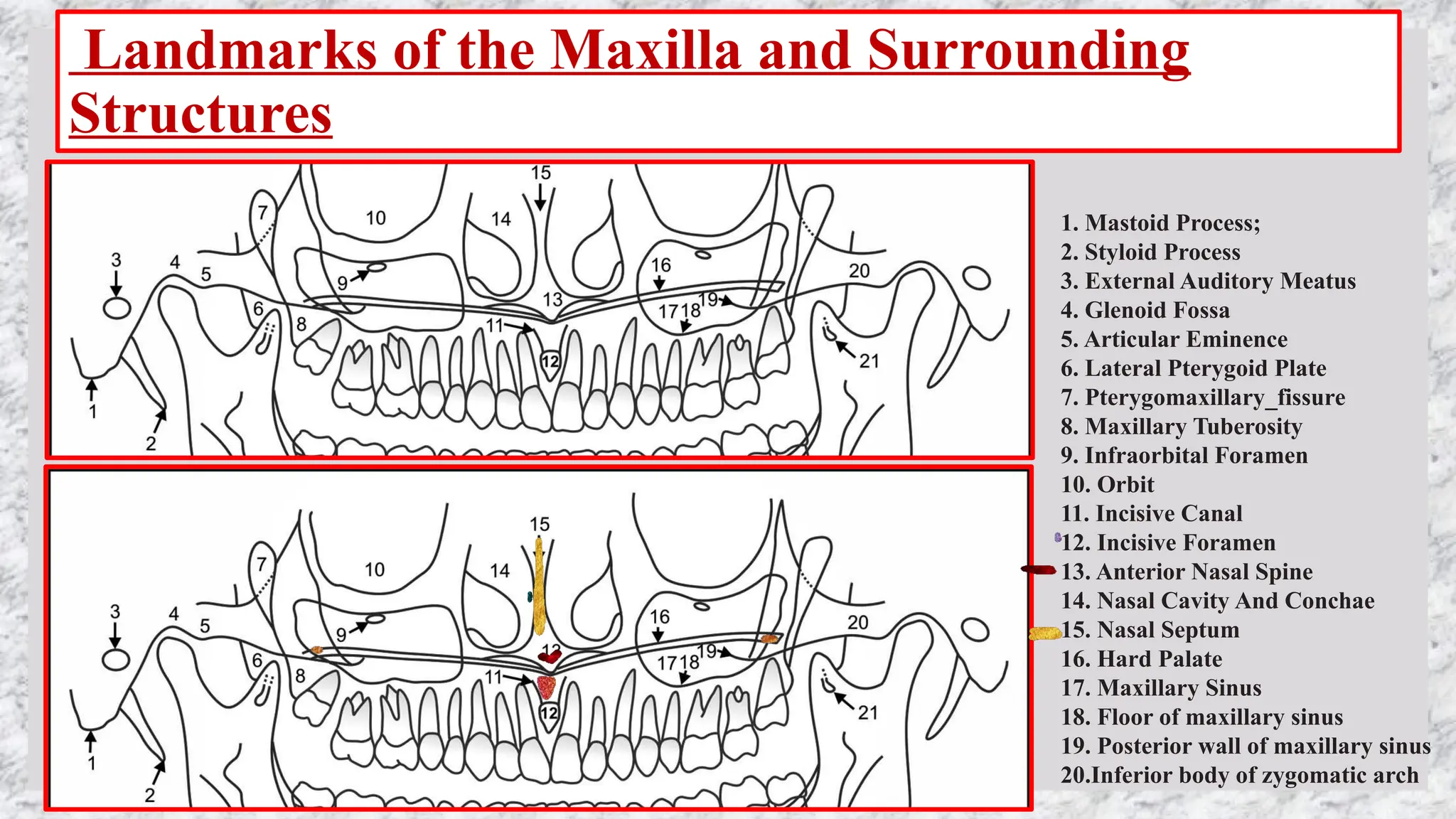
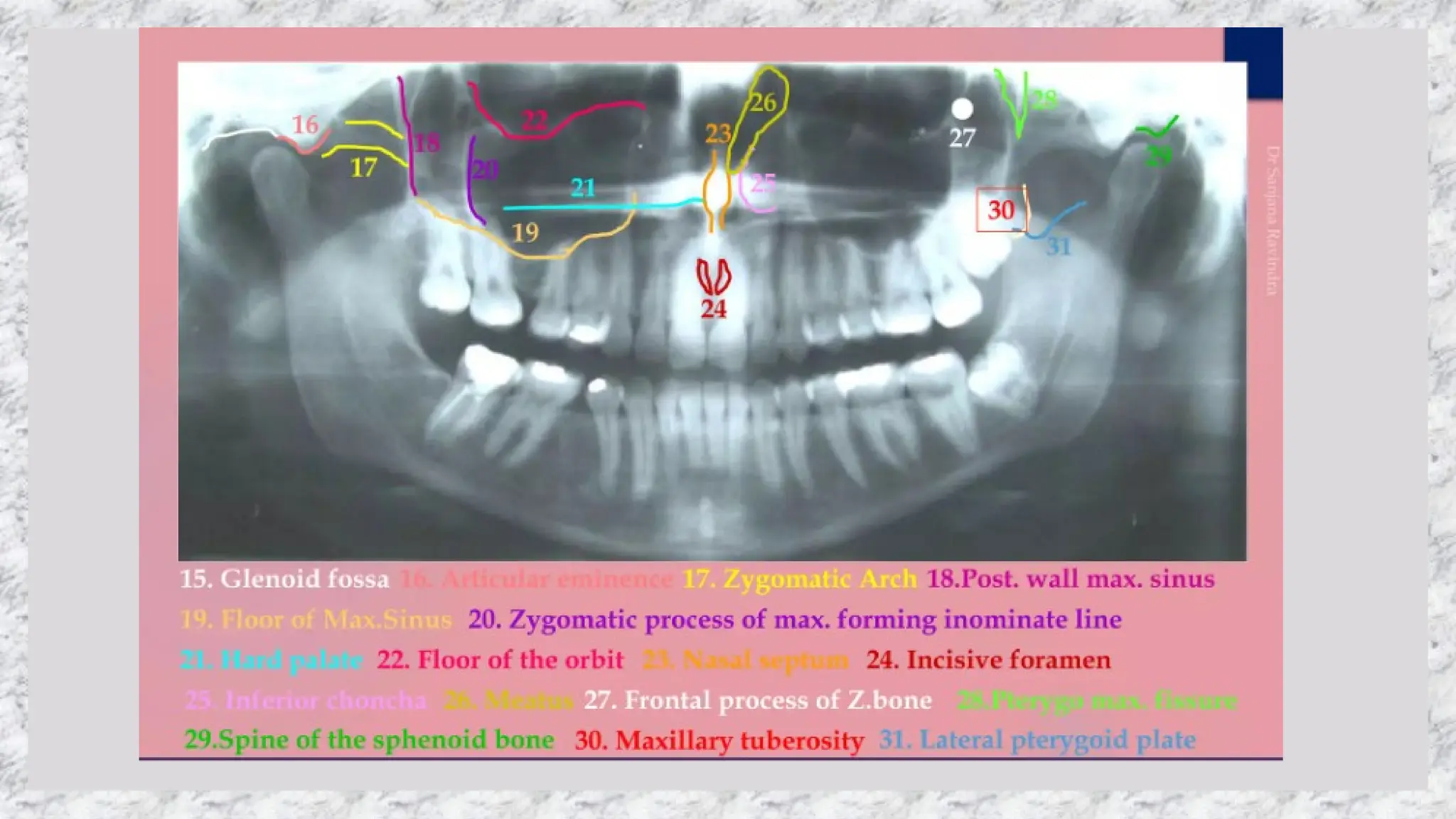
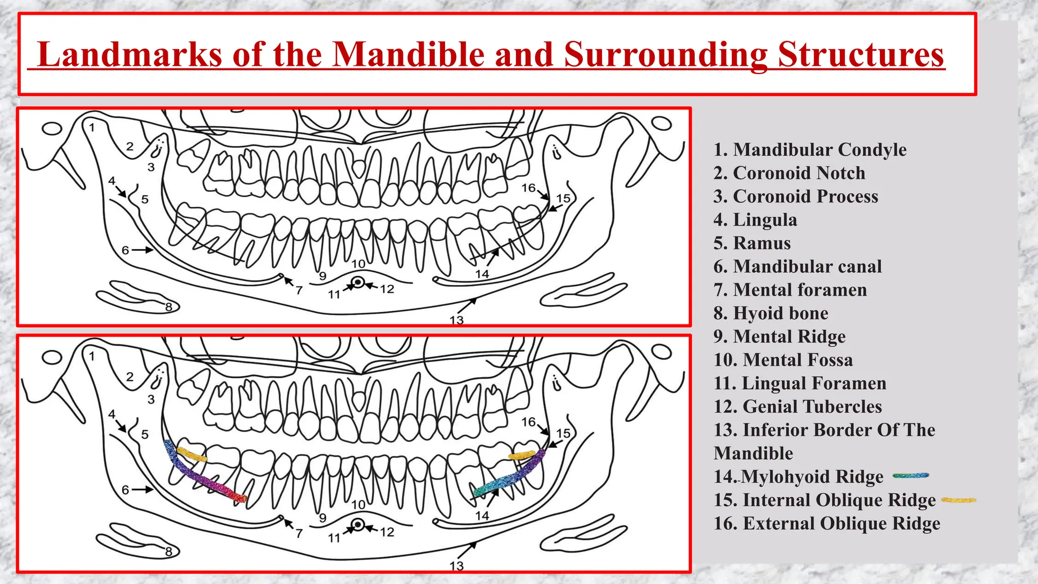
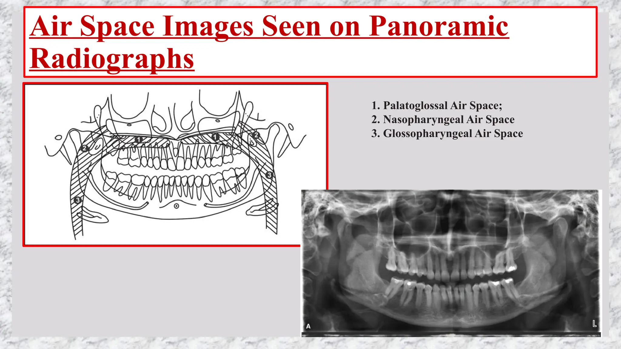
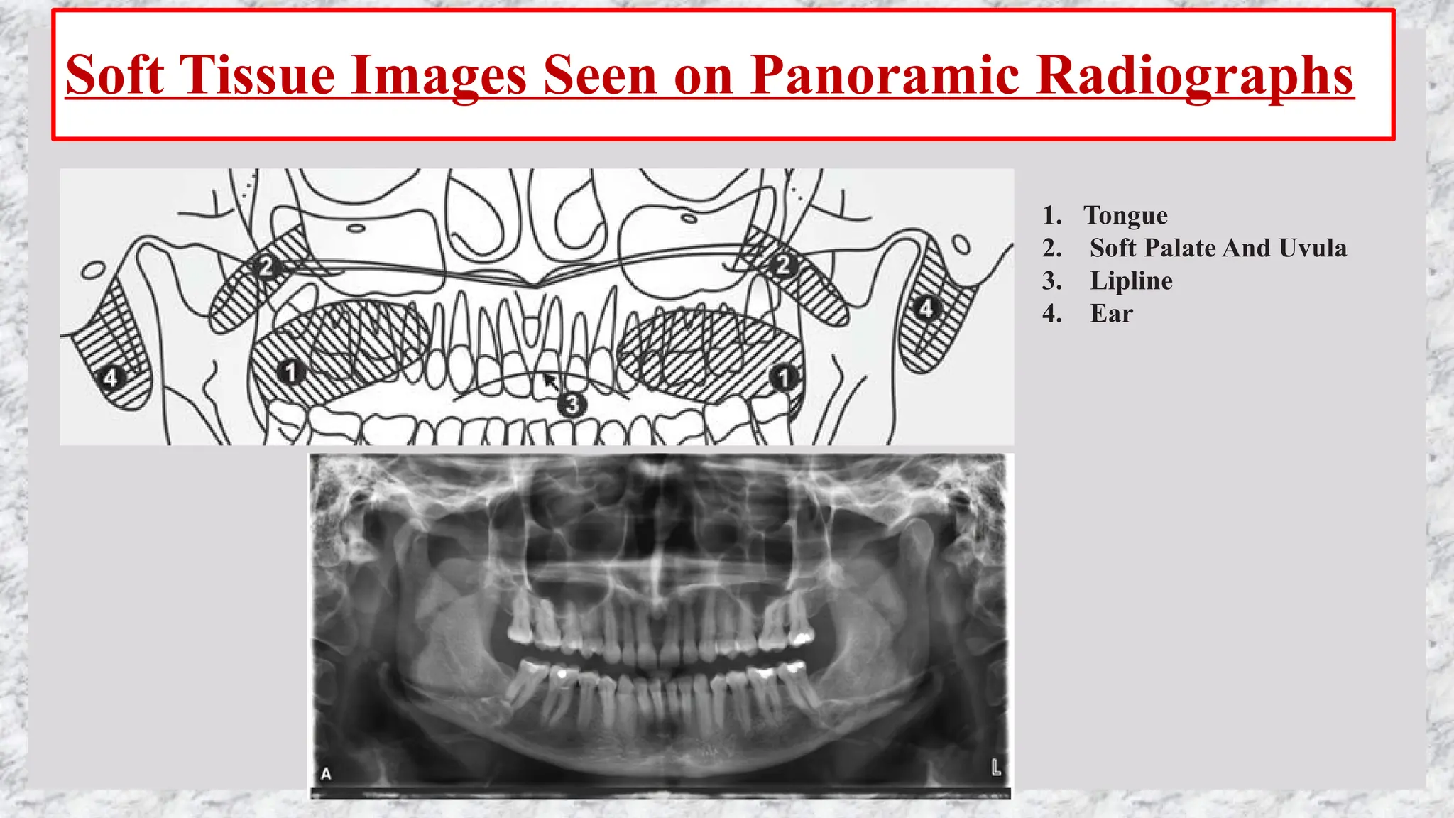
PANORAMIC
RADIOGRAPHY
DR PRIYANKA
ORAL MEDICINE AND RADIOLOGY
INTRODUCTION
• A radiographic procedure that produces a single tomographic image of facial structures including both
maxillary ad mandibular arches and their supporting structures.
• OTHER NAMES-
Pantamography
Orthopantamography
Rotational radiography
• Achieved by using a single rotation of the x-ray source and image receptor around the patient's head
WORKING PRINCIPLE
• First described by Paatero and Numata independently in 1948 and 1933, respectively
• Based on the principle of tomography and scanography.
• Tomography is defined as an unobstructed view of a structure in different directions without interference
from structures above or below that plane.
• Scanography or narrow beam radiography or slit beam radiography refers to a narrow beam of radiation
successively scanning different areas of the patient’s tissues to cast image in a single film.
• Narrow vertical negatively angled beam (−4 to −7°).
• The axis or pivotal point around which the cassette and the x-ray source rotate is the ‘rotation center’.
• The different types of rotation centers used by different manufacturers are the following:
1. Double-rotation center 2. Triple-rotation center 3. Continuously moving rotation center
• The dental arches must be positioned near to the focal trough to achieve the clearest image.
• The focal trough is defined as a three-dimensional curved zone in which structures are clearly
demonstrated.
• The structures located inside or outside the focal trough appear blurred or indistinct.
• The focal trough is narrow in the anterior region and wide in the posterior region.
• The size and shape of the focal trough varies according to the manufacturer.
• The closer the rotation center to the teeth, narrower the focal trough.
• The shape and width of the focal trough is determined by the path and velocity of the receptor and x-ray
tube head, alignment of the x-ray beam, and collimator width.
• The location of the focal trough can change with extensive machine use, so recalibration may be
necessary if consistently suboptimal images are being produced.
• Source and collimator are fixed
• rotating disk carries objects A–F
• Objects A–C move through the beam at the same rate and
direction as the image receptor and are imaged well.
• Objects D–F move through the beam at the same rate as
the receptor but in the opposite direction, and so their
images are blurred and reversed
• Rotating disk is fixed
• Source and receptor are rotating
• Objects A–C move through the beam at the same rate and
direction as the image receptor and are imaged well.
• Objects D–F move through the beam at the same rate as the
receptor but in the opposite direction, and so their images
are blurred and reversed
REAL IMAGE
• Objects that lie between the center of rotation and the receptor form a real image.
• Within this zone, objects that lie within the focal trough cast relatively sharp images,
DOUBLE IMAGE
• Objects that lie posterior to the center of rotation and that are intercepted twice by the x-ray beam form
double images.
• This region includes the hyoid bone, epiglottis, and cervical spine,
GHOST IMAGE
• Some objects are located between the x-ray source and the center of rotation.
• Ghost image is a radiopaque artifact seen in a panoramic film that is produced when a radiodense object is
penetrated twice by the x-ray beam.
• A ghost image resembles the real image
• it is seen on the opposite side of the film, it is indistinct, larger, and located at a higher level than the real
image.
• To avoid the occurrence of ghost image, the patient should be asked to remove all dense objects from the
head and neck region.
• EXAMPLE- right mandibular ramus lies between the x ray source and the center of rotation and its ghost
image is superimposed over the left side of the image
• hard palate and mandibular body and angle
IMAGE LAYER ANALYSIS
Objects
—
closest to film
will be
narrowed
Objects
—
closest or
toward the
source will be
widened
Buccal
—
objects
projected
lower
Lingual
—
objects
projected
higher
Objects in the
—
center of the
layer are
magnified 20-
30%
INDICATIONS
• DENTITION- Overall evaluation
• DENTAL PATHOLOGY- Examine for intraosseous pathology, such as cysts, tumors, or infections site, size, shape and extent
• TMJ - Gross evaluation
• Evaluation of position of impacted teeth
• Evaluation of eruption of permanent dentition or retained deciduous teeth
• Dentomaxillofacial trauma
• Developmental disturbances of maxillofacial skeleton
• Evaluation of bone disorders
• Evaluation of styloid process enlargement
• Pre and post operative surgeries
• Evaluation of sinus pathologies
• Multiple dental findings
• Assessment of alveolar bone height
• For patient education
EQUIPMENTS
• Panoramic X-ray unit:
1. X-Ray tube head:
 The collimator used is a lead plate with a slit, and the X-ray beam thus emerges through the
collimator as a narrow band.
 The vertical angulation of the panoramic tube head is not varied. It is in a fixed position
 The panoramic tube head always rotates behind the patients head as the film rotates in front of the
patient.
2. Head positioner: Consists of a chin rest, notched bite-block, forehead rest and lateral head support guides
3. Exposure controls: The milliamperage and kilovoltage settings are adjustable and can be varied to
accommodate patients of different sizes. The exposure time is fixed and cannot be changed
• kVp – 76 mA–15 Seconds – 15
Dose to the patient 0.103 mR +/–
0.008
• kVp – 80 mA–15 Seconds – 15
Dose to the Patient 0.116 mR +/–
0.008
PROCEDURE
1. Ask to remove all the objects from head and neck region
2. Explain the procedure to the patient and ask the patient to wear lead apron
3. Cover the bite block with a disposable plastic cover slip.
4. Set the exposure factors and adjust the height of the machine to accommodate the patient either in standing or sitting position.
5. Center the lower border of the mandible on the chin rest and is equidistant from each side.
6. Ask him to bite on groove with end to end position with anterior teeth on the plastic bite block.
7. The midsagittal plane should be perpendicular to the floor, the Frankfurt plane should be parallel to the floor,
8. Adjust the indicators lines- midsaggital, Frankfurt plane and canine lines.
 If the patient has a low palatal vault, increase the occlusal plane angulation slightly, if the patient has a high palatal vault
decrease the occlusal plane slightly.
9. The patients head should be immobilized by the head band.
10. Instruct the patient to position the tongue on the palate and ask him to remain still while the machine is rotating during
exposure
CONCEPTS
CONCEPT 1: STRUCTURES ARE FLATTENED AND SPREAD OUT
CONCEPT 2: MIDLINE STRUCTURES MAY PROJECT AS SINGLE IMAGES OR DOUBLE IMAGES
CONCEpT 3: GHOST IMAGES
CONCEPT 4: SOFT TISSUE OUTLINES ARE SEEN
CONCEPT 5 : AIR SPACES ARE SEEN CONCEPT - RELATIVE RADIOLUCENCIES AND RADIOPACITIES
ARE SEEN
CONCEPT 6: PANORAMIC RADIOGRAPHS ARE UNIQUE
DIAGNOSTIC CRITERIA
Landmarks of the Maxilla and Surrounding
Structures
1. Mastoid Process;
2. Styloid Process
3. External Auditory Meatus
4. Glenoid Fossa
5. Articular Eminence
6. Lateral Pterygoid Plate
7. Pterygomaxillary_fissure
8. Maxillary Tuberosity
9. Infraorbital Foramen
10. Orbit
11. Incisive Canal
12. Incisive Foramen
13. Anterior Nasal Spine
14. Nasal Cavity And Conchae
15. Nasal Septum
16. Hard Palate
17. Maxillary Sinus
18. Floor of maxillary sinus
19. Posterior wall of maxillary sinus
20.Inferior body of zygomatic arch
Landmarks of the Mandible and Surrounding Structures
1. Mandibular Condyle
2. Coronoid Notch
3. Coronoid Process
4. Lingula
5. Ramus
6. Mandibular canal
7. Mental foramen
8. Hyoid bone
9. Mental Ridge
10. Mental Fossa
11. Lingual Foramen
12. Genial Tubercles
13. Inferior Border Of The
Mandible
14.-Mylohyoid Ridge
15. Internal Oblique Ridge
16. External Oblique Ridge
Air Space Images Seen on Panoramic
Radiographs
1. Palatoglossal Air Space;
2. Nasopharyngeal Air Space
3. Glossopharyngeal Air Space
Soft Tissue Images Seen on Panoramic Radiographs
1. Tongue
2. Soft Palate And Uvula
3. Lipline
4. Ear
ADVANTAGES COMPARED WITH FULL
MOUTH EXAMINATION
• Broad coverage of facial bones and teeth
• Low radiation dose
• Ease of panoramic radiographic technique
• Can be used in patients with trismus or in patients who cannot tolerate intraoral radiography
• Quick and convenient radiographic technique
• Useful visual aid in patient education and case presentation
DISADVANTAGES
• Lower-resolution images that do not provide the fine details
• Magnification across image is unequal, making linear measurements unreliable
• Image is superimposition of real, double, and ghost images
• Requires accurate patient positioning to avoid positioning errors and artifacts
• cannot be used in the diagnosis of caries
• cannot be used in the evaluation of bone loss due to periodontal disease
• Image shows superimposition, especially in the premolar region
• Structures in the anterior region may not be well-defined
• Structures outside the image layer cannot be visualized
COMMON ERRORS
• ARTIFACT- is a structure or an appearance that is not normally present on the radiograph and is produced
by artificial means.
TYPES
• PATIENT POSITIONING ERROR
• FILM EXPOSING ERROR
• DARK ROOM AND PROCESSING ERROR
• ERRORS IN HANDLING THE FILMS
NOT NOTICED
NOWADAYS BECAUSE
OF DIGITAL OPG
MACHINES
THE PATIENT IS POSITIONED
TOO FAR FORWARD.
• Vertical elongation of teeth
• Superimposition of real image of
cervical spine over the condyles
bilaterally.
• Static electricity marks are also
noted (white arrows).
THE PATIENT IS POSITIONED
TOO FAR BACK.
• Horizontal magnification of
structures, especially anterior
teeth.
• Ghost image of left ramus (white
arrows) appears superimposed
over the right side
THE PATIENT’S CHIN IS TOO
HIGH
• Reverse smile
• (A) Oropharyngeal airspace (RL),
• (B) palatoglossal airspace (RL),
• (C) ghost image of cervical spine
(RO),
• (D) epiglottis,
• (E) earlobe and
• (F) styloid process
THE PATIENT’S CHIN IS TOO
LOW
• downward shift of the chin and
• upward placement of the condyles
close to the upper edge of the
film.
• (A) Soft palate (RO),
• (B) oropharyngeal airspace (RL)
overlapped over ramus and
• (C) hyoid bone
THE PATIENT IS TWISTED.
• Horizontal magnification of teeth
on patient’s right and mandibular
ramus compared to the left side.
• Real image of cervical spine is
visible on left,
• Ghost of spine (white arrow) is
observed as a blurry radiopaque
image in the midline
THE TONGUE IS NOT ON THE
PALATE.
• Radiolucent area (palatoglossal
airspace, RL) just under the hard
palate.
THE LEAD APRON IS TOO HIGH
AT THE PATIENT’S NECK.
• Overlap of an inverted V-shaped
radiopacity in the midline (A).
• (B) Fracture line and
• (C) inferior concha and turbinate.
THE PATIENT IS MOVED DURING
THE PROCEDURE.
• Wavy outline of the structures
(white arrows).
Near to film - smaller
MID SAGGITAL PLANE
ERROR
GHOST IMAGE OF EARRINGS AND
SPECTACLES
1. Under exposure
2. Insufficient ma
3. Insufficient kvp
1. Over Exposure
2. Excessive mA
3. Excessive kVP
LOW DENSITY HIGH DENSITY
‘TREE-BRANCH-SHAPED’
STATIC ELECTRICITY
ARTEFACT (BLACK
ARROW) OVERLAPPED
OVER LEFT RAMUS.
• Pneumatisation of right
floor of the maxillary sinus
(A).
• (B) Bite-block,
• (C) real image of the hard
palate,
• (D) ghost image of the hard
palate and
• (E) anterior nasal spine.
RECENT ADVANCEMENTS
• Measurement of distances and angles in treatment planning
• Evaluation of asymmetric patients.
• Panoramic localization
• Injection of radiopaque medium
• Visualization of specific anatomic regions
• Reverse panorama radiograph
• Vertical tube shift technique

OPG (ORTHOPANTOMOGRAPHY) - PANORAMIC RADIOGRAPHY- DR PRIYANKA

  • 1.
  • 2.
    INTRODUCTION • A radiographicprocedure that produces a single tomographic image of facial structures including both maxillary ad mandibular arches and their supporting structures. • OTHER NAMES- Pantamography Orthopantamography Rotational radiography • Achieved by using a single rotation of the x-ray source and image receptor around the patient's head
  • 4.
    WORKING PRINCIPLE • Firstdescribed by Paatero and Numata independently in 1948 and 1933, respectively • Based on the principle of tomography and scanography. • Tomography is defined as an unobstructed view of a structure in different directions without interference from structures above or below that plane. • Scanography or narrow beam radiography or slit beam radiography refers to a narrow beam of radiation successively scanning different areas of the patient’s tissues to cast image in a single film. • Narrow vertical negatively angled beam (−4 to −7°). • The axis or pivotal point around which the cassette and the x-ray source rotate is the ‘rotation center’. • The different types of rotation centers used by different manufacturers are the following: 1. Double-rotation center 2. Triple-rotation center 3. Continuously moving rotation center
  • 6.
    • The dentalarches must be positioned near to the focal trough to achieve the clearest image. • The focal trough is defined as a three-dimensional curved zone in which structures are clearly demonstrated. • The structures located inside or outside the focal trough appear blurred or indistinct. • The focal trough is narrow in the anterior region and wide in the posterior region. • The size and shape of the focal trough varies according to the manufacturer. • The closer the rotation center to the teeth, narrower the focal trough. • The shape and width of the focal trough is determined by the path and velocity of the receptor and x-ray tube head, alignment of the x-ray beam, and collimator width. • The location of the focal trough can change with extensive machine use, so recalibration may be necessary if consistently suboptimal images are being produced.
  • 7.
    • Source andcollimator are fixed • rotating disk carries objects A–F • Objects A–C move through the beam at the same rate and direction as the image receptor and are imaged well. • Objects D–F move through the beam at the same rate as the receptor but in the opposite direction, and so their images are blurred and reversed
  • 8.
    • Rotating diskis fixed • Source and receptor are rotating • Objects A–C move through the beam at the same rate and direction as the image receptor and are imaged well. • Objects D–F move through the beam at the same rate as the receptor but in the opposite direction, and so their images are blurred and reversed
  • 10.
    REAL IMAGE • Objectsthat lie between the center of rotation and the receptor form a real image. • Within this zone, objects that lie within the focal trough cast relatively sharp images,
  • 11.
    DOUBLE IMAGE • Objectsthat lie posterior to the center of rotation and that are intercepted twice by the x-ray beam form double images. • This region includes the hyoid bone, epiglottis, and cervical spine,
  • 12.
    GHOST IMAGE • Someobjects are located between the x-ray source and the center of rotation. • Ghost image is a radiopaque artifact seen in a panoramic film that is produced when a radiodense object is penetrated twice by the x-ray beam. • A ghost image resembles the real image • it is seen on the opposite side of the film, it is indistinct, larger, and located at a higher level than the real image. • To avoid the occurrence of ghost image, the patient should be asked to remove all dense objects from the head and neck region. • EXAMPLE- right mandibular ramus lies between the x ray source and the center of rotation and its ghost image is superimposed over the left side of the image • hard palate and mandibular body and angle
  • 15.
    IMAGE LAYER ANALYSIS Objects — closestto film will be narrowed Objects — closest or toward the source will be widened Buccal — objects projected lower Lingual — objects projected higher Objects in the — center of the layer are magnified 20- 30%
  • 16.
    INDICATIONS • DENTITION- Overallevaluation • DENTAL PATHOLOGY- Examine for intraosseous pathology, such as cysts, tumors, or infections site, size, shape and extent • TMJ - Gross evaluation • Evaluation of position of impacted teeth • Evaluation of eruption of permanent dentition or retained deciduous teeth • Dentomaxillofacial trauma • Developmental disturbances of maxillofacial skeleton • Evaluation of bone disorders • Evaluation of styloid process enlargement • Pre and post operative surgeries • Evaluation of sinus pathologies • Multiple dental findings • Assessment of alveolar bone height • For patient education
  • 17.
    EQUIPMENTS • Panoramic X-rayunit: 1. X-Ray tube head:  The collimator used is a lead plate with a slit, and the X-ray beam thus emerges through the collimator as a narrow band.  The vertical angulation of the panoramic tube head is not varied. It is in a fixed position  The panoramic tube head always rotates behind the patients head as the film rotates in front of the patient. 2. Head positioner: Consists of a chin rest, notched bite-block, forehead rest and lateral head support guides 3. Exposure controls: The milliamperage and kilovoltage settings are adjustable and can be varied to accommodate patients of different sizes. The exposure time is fixed and cannot be changed
  • 18.
    • kVp –76 mA–15 Seconds – 15 Dose to the patient 0.103 mR +/– 0.008 • kVp – 80 mA–15 Seconds – 15 Dose to the Patient 0.116 mR +/– 0.008
  • 19.
    PROCEDURE 1. Ask toremove all the objects from head and neck region 2. Explain the procedure to the patient and ask the patient to wear lead apron 3. Cover the bite block with a disposable plastic cover slip. 4. Set the exposure factors and adjust the height of the machine to accommodate the patient either in standing or sitting position. 5. Center the lower border of the mandible on the chin rest and is equidistant from each side. 6. Ask him to bite on groove with end to end position with anterior teeth on the plastic bite block. 7. The midsagittal plane should be perpendicular to the floor, the Frankfurt plane should be parallel to the floor, 8. Adjust the indicators lines- midsaggital, Frankfurt plane and canine lines.  If the patient has a low palatal vault, increase the occlusal plane angulation slightly, if the patient has a high palatal vault decrease the occlusal plane slightly. 9. The patients head should be immobilized by the head band. 10. Instruct the patient to position the tongue on the palate and ask him to remain still while the machine is rotating during exposure
  • 20.
    CONCEPTS CONCEPT 1: STRUCTURESARE FLATTENED AND SPREAD OUT CONCEPT 2: MIDLINE STRUCTURES MAY PROJECT AS SINGLE IMAGES OR DOUBLE IMAGES CONCEpT 3: GHOST IMAGES CONCEPT 4: SOFT TISSUE OUTLINES ARE SEEN CONCEPT 5 : AIR SPACES ARE SEEN CONCEPT - RELATIVE RADIOLUCENCIES AND RADIOPACITIES ARE SEEN CONCEPT 6: PANORAMIC RADIOGRAPHS ARE UNIQUE
  • 21.
  • 22.
    Landmarks of theMaxilla and Surrounding Structures 1. Mastoid Process; 2. Styloid Process 3. External Auditory Meatus 4. Glenoid Fossa 5. Articular Eminence 6. Lateral Pterygoid Plate 7. Pterygomaxillary_fissure 8. Maxillary Tuberosity 9. Infraorbital Foramen 10. Orbit 11. Incisive Canal 12. Incisive Foramen 13. Anterior Nasal Spine 14. Nasal Cavity And Conchae 15. Nasal Septum 16. Hard Palate 17. Maxillary Sinus 18. Floor of maxillary sinus 19. Posterior wall of maxillary sinus 20.Inferior body of zygomatic arch
  • 24.
    Landmarks of theMandible and Surrounding Structures 1. Mandibular Condyle 2. Coronoid Notch 3. Coronoid Process 4. Lingula 5. Ramus 6. Mandibular canal 7. Mental foramen 8. Hyoid bone 9. Mental Ridge 10. Mental Fossa 11. Lingual Foramen 12. Genial Tubercles 13. Inferior Border Of The Mandible 14.-Mylohyoid Ridge 15. Internal Oblique Ridge 16. External Oblique Ridge
  • 26.
    Air Space ImagesSeen on Panoramic Radiographs 1. Palatoglossal Air Space; 2. Nasopharyngeal Air Space 3. Glossopharyngeal Air Space
  • 27.
    Soft Tissue ImagesSeen on Panoramic Radiographs 1. Tongue 2. Soft Palate And Uvula 3. Lipline 4. Ear
  • 28.
    ADVANTAGES COMPARED WITHFULL MOUTH EXAMINATION • Broad coverage of facial bones and teeth • Low radiation dose • Ease of panoramic radiographic technique • Can be used in patients with trismus or in patients who cannot tolerate intraoral radiography • Quick and convenient radiographic technique • Useful visual aid in patient education and case presentation
  • 29.
    DISADVANTAGES • Lower-resolution imagesthat do not provide the fine details • Magnification across image is unequal, making linear measurements unreliable • Image is superimposition of real, double, and ghost images • Requires accurate patient positioning to avoid positioning errors and artifacts • cannot be used in the diagnosis of caries • cannot be used in the evaluation of bone loss due to periodontal disease • Image shows superimposition, especially in the premolar region • Structures in the anterior region may not be well-defined • Structures outside the image layer cannot be visualized
  • 30.
    COMMON ERRORS • ARTIFACT-is a structure or an appearance that is not normally present on the radiograph and is produced by artificial means. TYPES • PATIENT POSITIONING ERROR • FILM EXPOSING ERROR • DARK ROOM AND PROCESSING ERROR • ERRORS IN HANDLING THE FILMS NOT NOTICED NOWADAYS BECAUSE OF DIGITAL OPG MACHINES
  • 31.
    THE PATIENT ISPOSITIONED TOO FAR FORWARD. • Vertical elongation of teeth • Superimposition of real image of cervical spine over the condyles bilaterally. • Static electricity marks are also noted (white arrows). THE PATIENT IS POSITIONED TOO FAR BACK. • Horizontal magnification of structures, especially anterior teeth. • Ghost image of left ramus (white arrows) appears superimposed over the right side
  • 32.
    THE PATIENT’S CHINIS TOO HIGH • Reverse smile • (A) Oropharyngeal airspace (RL), • (B) palatoglossal airspace (RL), • (C) ghost image of cervical spine (RO), • (D) epiglottis, • (E) earlobe and • (F) styloid process THE PATIENT’S CHIN IS TOO LOW • downward shift of the chin and • upward placement of the condyles close to the upper edge of the film. • (A) Soft palate (RO), • (B) oropharyngeal airspace (RL) overlapped over ramus and • (C) hyoid bone
  • 33.
    THE PATIENT ISTWISTED. • Horizontal magnification of teeth on patient’s right and mandibular ramus compared to the left side. • Real image of cervical spine is visible on left, • Ghost of spine (white arrow) is observed as a blurry radiopaque image in the midline THE TONGUE IS NOT ON THE PALATE. • Radiolucent area (palatoglossal airspace, RL) just under the hard palate.
  • 34.
    THE LEAD APRONIS TOO HIGH AT THE PATIENT’S NECK. • Overlap of an inverted V-shaped radiopacity in the midline (A). • (B) Fracture line and • (C) inferior concha and turbinate. THE PATIENT IS MOVED DURING THE PROCEDURE. • Wavy outline of the structures (white arrows).
  • 35.
    Near to film- smaller MID SAGGITAL PLANE ERROR
  • 36.
    GHOST IMAGE OFEARRINGS AND SPECTACLES
  • 37.
    1. Under exposure 2.Insufficient ma 3. Insufficient kvp 1. Over Exposure 2. Excessive mA 3. Excessive kVP LOW DENSITY HIGH DENSITY
  • 38.
    ‘TREE-BRANCH-SHAPED’ STATIC ELECTRICITY ARTEFACT (BLACK ARROW)OVERLAPPED OVER LEFT RAMUS. • Pneumatisation of right floor of the maxillary sinus (A). • (B) Bite-block, • (C) real image of the hard palate, • (D) ghost image of the hard palate and • (E) anterior nasal spine.
  • 39.
    RECENT ADVANCEMENTS • Measurementof distances and angles in treatment planning • Evaluation of asymmetric patients. • Panoramic localization • Injection of radiopaque medium • Visualization of specific anatomic regions • Reverse panorama radiograph • Vertical tube shift technique