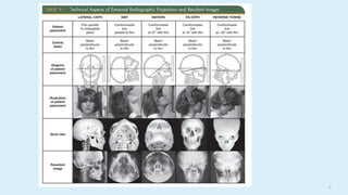
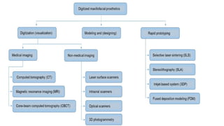
IMAGING TECHNIQUES
2
CONTENTS
 Introduction
 Types of dental radiographs
Intraoral
Extraoral
 Digital imaging
 Radiographs in complete denture
 Radiographs in RPD
 Radiographs in FPD
 Implant imaging
 Radiographs in maxillofacial prosthodontics
 Conclusion
 References
3
INTRODUCTION
Dental radiographs are a necessary component of comprehensive patient care.
In dentistry, radiographs enable the dental professional to identify many condition that
may otherwise go undetected clinically.
4
Uses of dental radiographs:
1. To detect lesions, disease and conditions of teeth and surrounding structures that
cannot be identified clinically
2. To localize lesions or foreign objects.
3.To evaluate growth and development.
4. To illustrate changes secondary to caries, periodontal disease and trauma.
5. To document the condition of patient at a specific point of time.
5
TYPES OF DENTAL RADIOGRAPHS
1.Intraoral radiographs: divided into 3 categories
Periapical
Bitewing
Occlusal
2.Extraoral radiographs
Panoramic imaging
Lateral cephalometric
6
Submentovertex
Posteroanterior cephalometric
Revers Towne
Waters
Cone beam computed tomography
3.Others
Computed tomographic scanning (CT)
Magnetic resonance imaging (MRI)
Ultrasonography
7
 2D imaging techniques:
Periapical
Charged coupled device
Occlusual
Bitewing
Panoramic
Cephalomeric
 3D imaging techniques :
Tomography
Computerized cone beam tomography
Magnetic resonanace
8
X-RAY FILM
COMPOSITION
X-ray film has two principal components:
(1) emulsion and
(2)base.
9
1 0
11
INTRAORAL PROJECTIONS
PERIAPICAL IMAGING : Periapical radiograph shows all of a tooth, including the
surrounding bone.
Two intraoral projection techniques are commonly used for periapical imaging:
a. The paralleling technique and
b. The bisecting angle technique.
paralleling technique is the most appropriate technique for digital imaging.
1 2
PARALLELING TECHNIQUE
Principle: The central concept of the
paralleling is that the x-ray receptor is
supported parallel to the long axis of
the teeth, and the central ray of the x-
ray beam is directed at right angles to
the teeth and receptor.
1 3
 Receptor should be positioned parallel to the teeth and deep in pateints
mouth
14
BISECTING-ANGLE TECHNIQUE
1 5
LIMITATIONS :
• To reproduce the length of each root of a multirooted tooth accurately, the central
beam must be angled differently for each root
• alveolar ridge often projects more coronally than its true position, thus distorting
the apparent height of the alveolar bone around the teeth.
 The plane of the receptor and the long axis of the teeth form an angle with its apex at the
point where the receptor is in contact with the teeth along an imaginary line that bisects
this angle and directs the central ray of the beam at right angles to this bisector.
 This forms two triangles with two equal angles and a common side (the imaginary
bisector).
16
ANGULATION GUIDELINES FOR BISECTING ANGLE PROJECTION
17
• Intermaxillary suture
• Anterior nasal spine
• Nasal fossae and floor of the nasal fossae
• Nasal septum
• Incisive foramen
• Tip of the nose shadow
• Lateral fossa ,Canine fossa
• Nasopalatine canal
• Superior foramina of the nasopalatine canal
• Nasolacrimal canal
• Nasolabial fold
• Inverted Y line of Innes
• Maxillary sinus
• Zygomatic process and zygomatic bone
• Maxillary tuberosity
• Pterygoid plates
• Hamular process
• Coronoid process of the mandible
LANDMARKS UNIQUE TO THE MAXILLARY INTRAORAL PERIAPICAL RADIOGRAPH
18
1 9
2 0
21
LANDMARKS UNIQUE TO THE MANDIBULAR INTRAORAL PERIAPICAL RADIOGRAPH
• Symphysis
• Genial tubercles
• Mental ridge
• Mental fossa
• Mental foramen
• Mandibular canal
• Mylohyoid ridge
• Submandibular gland fossa
• External oblique ridge
• Inferior border of mandible
2 2
2 3
2 4
BITEWING
 Bitewing (also called interproximal)
images, include the crowns of the
maxillary and mandibular teeth and the
alveolar crest on the same receptor.
 Bitewing technique is used for detecting
interproximal caries in the early stages of
development before it becomes clinically
apparent these radiographs also may
reveal secondary caries below
restorations
2 5
 this technique is also useful for evaluating the periodontal condition.
 They provide a good perspective of the alveolar bone crest, and changes in
bone height can be assessed accurately through comparison with the adjacent
teeth.
Horizontal Bitewing Receptors:To obtain the desirable characteristics of the
bitewing examination described, the beam is carefully aligned between the
teeth and parallel with the occlusal plane.
2 6
Vertical Bitewing Receptors : used when the patient has moderate to
extensive alveolar bone loss. Orienting the length of the receptor vertically
increases the likelihood that the residual alveolar crests in the maxilla and
the mandible will be recorded on the radiograph
Set of vertical bitewing views
2 7
OCCLUSAL IMAGING
Occlusal images show an area of teeth and bone larger than periapical images
 It may include the palate or floor of the mouth and a reasonable extent of the adjacent
lateral structures.
 Because occlusal radiographs are exposed at a steep angulation, they may be used with
conventional periapical images to determine the location of objects in all three
dimensions.
2 8
The occlusal radiograph is especially useful in the following cases:
• To locate precisely roots and supernumerary, unerupted, and impacted
teeth
• To localize foreign bodies in the jaws and stones in the ducts of
sublingual and submandibular glands
• To evaluate the integrity of the anterior, medial, and lateral outlines of the
maxillary sinus
• In the examination of patients with trismus,
• To obtain information about the location, nature, extent of fractures of the
mandible and maxilla
2 9
• To determine the medial and lateral extent of
disease (e.g., cysts, osteomyelitis,
malignancies) and to detect disease in the
palate or floor of the mouth
Radiographic examination of primary
dentition anterior occlusal views,
3 0
Tube-shift technique/buccal-object rule/ Clark’s rule
Clark described this method in 1910.
The rationale for this procedure derives from the manner in which the
relative positions of radiographic images of two separate objects
change when the projection angle at which the images were made is
changed. ,
SLOB: same lingual, opposite buccal
31
Thus if the object in question appears to move in the same direction with respect
to the reference structures as does the x-ray tube, it is on the lingual aspect of the
reference object; if it appears to move in the opposite direction as the x-ray tube,
it is on the buccal aspect. If it does not move with respect to the reference
object, it lies at the same depth as reference object.
3 2
DIGITAL IMAGING
The two main technologies are:
solid-state technology
• Charged coupled device
• Complementary metal oxide semiconductors
• Flat pannel detectors
photostimulable phosphor (PSP) technology.
• Stationary plate scans
• Rotating plate scans
3 3
Intra-oral imaging using electronic or charge-coupled device imaging techniques
 Charge-coupled device (CCD) detectors consist of a serial chain of signal
components, such as phosphors, fiber optics or lenses, image intensifiers, and the
CCD, which serve to convert the X-ray energy to light or electron-hole pairs and to
record spatially resolved image.
 With CCDs, pre-surgical implant assessment of a single site becomes precise.
 CCD provides accurate measurement of implant sites preoperatively and gives
information about osseo-integration postoperatively.
3 4
Complementary metal oxide semiconductor (CMOS) technology
is the basis for typical consumer-grade digital cameras
This technology is used for intraoral imaging applications
Flat Panel Detectors
Flat panel detectors are used for medical imaging but have also been used in
several extraoral imaging devices.
3 5
PHOTOSTIMULABLE PHOSPHOR
 PSP plates absorb and store energy from x rays and release this energy as light
(phosphorescence) when stimulated by another light of an appropriate wavelength.
 Flat panel detectors are expensive and likely to be limited to specialized
imaging tasks as cone beam computed tomography.
3 6
EXTRA ORAL RADIOGRAPHS: are produced with conventional dental x-ray machines,
certain models of panoramic machines, or higher capacity medical x-ray units.
Cephalometric and skull views require at least a 20 cm × 25 cm (8 inch × 10 inch) image
receptor.
Panoramic imaging
Lateral jaw projection
Lateral skull (cephalometric )
Submentovertex
Posteroanterior cephalometric
Revers Towne
Waters
37
3 8
CEPHALOMETRIC RADIOGRAPHS
cephalometric radiography helps in the analysis of the quality of the bony site (ratio of
compact to cancellous bone), especially in the anterior region of the mandible
 may be either frontal (posteroanterior) or lateral skull projections
 Cephalometric means measurements of the head.
 Cephalometer is a device used to Standardize the placement of the head during
exposure.
 Either conventional x- ray machines modified for cephalometric work or special units
may be needed.
3 9
Cephalometric Radiographs :Lateral skull (cephalometric )projection:
 It shows the entire skull from the side and the X-ray passes from the lateral side
Purpose:
1.Pre and post treatment records.
2. Evaluate the growth and development
3. Facial soft tissue profile of the face
4. Trauma
5. Pathology
6.Developmental Abnormalities
4 0
Posteroanterior (PA) cephalometric projection:
 Shows the entire skull in a postero-anterior plane.
 The beam passes through the skull in a posterior to anterior
direction.
Purpose:
• Asymmetry
• Disease
• Trauma
• Developmental abnormalities
41
PANORAMIC IMAGING
Panoramic imaging (also called pantomography) is a technique for producing a single
image of the facial structures that includes both the maxillary and the mandibular dental
arches and their supporting structures
INDICATIONS
• Overall evaluation of dentition
• Examine for intraosseous pathology, such as cysts, tumors, or infections
• Gross evaluation of temporomandibular joints
• Evaluation of position of impacted teeth
• Evaluation of eruption of permanent dentition
• Dentomaxillofacial trauma
4 2
ADVANTAGES
• Broad coverage of facial bones and teeth
• Low radiation dose
• Ease of panoramic radiographic technique
• Can be used in patients with trismus or in patients who cannot tolerate intraoral
radiography
• Quick and convenient radiographic technique
• Useful visual aid in patient education and case presentation
Developmental disturbances of maxillofacial skeleton
4 3
• Requires accurate patient positioning to avoid positioning errors and artifacts.
• Difficult to image both jaws when patient has severe maxillomandibular
discrepancy
DISADVANTAGES
• Lower resolution images
• Magnification across image is unequal, making linear measurements unreliable
• Image is superimposition of real, double, and ghost images and requires careful
visualization to decipher anatomic and pathologic details
4 4
4 5
CONE-BEAM COMPUTED TOMOGRAPHIC (CBCT) IMAGING
 The introduction of CBCT imaging has heralded a shift from a two-
dimensional to a volumetric approach in maxillofacial imaging.There are
three main components to CBCT imaging: (1) image production, (2)
visualization, and (3) interpretation.
 It uses a divergent or “cone” -shaped source of ionizing radiation and a two-
dimensional area detector fixed on a rotating gantry to acquire multiple
sequential projection images in one complete scan around the area of interest.
4 6
Advantages
• it generates a 3D dataset has the potential for generating all 2D
images (e.g. orthopantomogram, lateral cephalogram), and allows vertical scanning with
the patient in a seated position.
• It generates high-resolution images of anatomical structures, bone trabeculae,
periodontal ligament (PDL), and root formation.
• rapid scanning procedure, lower radiation dose, reduced disturbance from metal
artifacts, lower cost, easy accessibility, easy handling.
47
Disadvantages.
• It has a low contrast range,
• restricted field of view (FOV),limited information on soft tiossue structures
• reduced scanned volume
COMPUTED TOMOGRAPHIC IMAGE
 CT was invented by Sir Godfrey Hounsfield and was introduced in
1972.This modality gives rise to high-density resolution images, and allows
soft tissues to be visualized.
 CT scan provides tangential and cross-sectional tomographic images of the
implant site
4 8
MAGNETIC RESONANCE IMAGING
 To make an MR image, the patient is first placed inside a large magnet.
 This magnetic field causes the nuclei of many atoms in the body, particularly
hydrogen, to align with the magnetic field.
Advantages: non invasive, using nonionizing radiation, and making high-quality
images of soft tissue resolution in any imaging plane.
Disadvantages : high cost, long scan times, and the fact that various metals in
the imaging field either distort the image or may move into the strong magnetic
field, injuring the patient.
4 9
APPLICATIONS
 MR imaging is useful in evaluating soft tissue conditions, such as the position and
integrity of the disk in the TMJ , evaluating soft tissue disease, especially
neoplasia involving the soft tissues, such as tongue, cheek, salivary glands, and
neck; determining malignant involvement of lymph nodes;perineural invasion by
malignant neoplasia.
 In osteomyelitis, it is used to visualize edematous changes in the fatty marrow as
well as the surrounding soft tissue.
 It also may be useful in identifying the location of the mandibular nerve in cases
where it is not clearly seen on panoramic or CBCT images.
5 0
ULTRASONOGRAPHY
 Sonography is a technique based on sound waves that acquires images in
real time without the use of ionizing radiation.
 Ultrasonography is used in the head and neck region for evaluation of
neoplasms in the thyroid, parathyroid, salivary glands, or lymph nodes;
stones in salivary glands or ducts; Sjögren’s syndrome, and the vessels of
the neck, including the carotid artery for atherosclerotic plaques.
51
RADIOGRAPHIC INTERPRETATION IN REMOVABLE PARTIAL DENTURE
The complete oral examination must include both clinical and radiographic
interpretation of
(1) caries,
(2) the condition of existing restorations
(3) periodontal conditions,
(4) responses of teeth (especially abutment teeth) and residual ridges to previous stress,
and
(5) the vitality of remaining teeth.
5 2
BONE INDEX AREAS
 Index areas are those areas of alveolar support that disclose the reaction of bone to
additional stress.
 There might be a positive Bone factor or a Negative Bone factor depending on the
response of the alveolar bone to additional loading.
A positive or a favorable response
• A decrease in the trabecular pattern (bone condensation)
• A heavy cortical layer.
• Dense lamina dura
• Normal bone height
• Normal periodontal ligament space.
5 3
Teeth that have been subjected to greater than normal stress and provide good index
information are:-
• Abutment teeth of an FPD or RPD.
• Teeth involved in occlusal interferences.
• Teeth receiving greater occlusal stress due to loss of adjacent teeth.
• Tipped teeth with occlusal contact.
Retrograde or negative response
→ loss of lamina dura
→ decrease bone height
→ widening of periodontal ligament space
→ apical and furcation radioluscency
5 4
Radioluscent or radioopaque lesions.
→ The presence of cysts, abcesses, embedded teeth or roots or
foreign bodies must be noted.
→ A surgical diagnosis and treatment must be planned so that a conditions does
not flare up later on effecting the prognosis of the prosthesis.
5 5
RADIOGRAPHIC INVESTIGATIONS IN FIXED PARTIAL DENTURES
A well defined, complete mouth radiographic series is essential.
TMJ radiographs may be indicated for patients with joint dysfunction and a panoramic
radiograph can also be helpful.
Radiographs used in FPD are
1. Full mouth intra-oral periapical radiographs
2. Panoramic radiographs.
3. TMJ radiographs.
5 6
3. Quality of supporting bone trabacular patterns and reaction to functional charges.
4. Width of the periodontal ligament spaces and evidence of traum from occlusion.
5. Areas of vertical and horizontal osseous resorption and furcation invasions.
2. Root number and morphology (short, long, slender, broad, bifurcated, fused
dilacerated etc) and root proximity. Molar with divergent roots provide better support
than a molar with little or no inter radicular bone
An intra oral radiographic examination reveals.
1. Remaining bone support After horizontal bone loss from periodontal disease
the PDL supported root surface area can be dramatically reduced.
5 7
9.Presence of apical diseases, root resorption or root fractures.
10. Retained root fragments, radiolucent areas, calcification, foreign bodies, or impacted
teeth
11. Presence of carious lesions and restorations to the pulp and alveolar crest, calculus
deposits
14. Oral radiographic manifestation of systemic disease.
6. Axial inclination of teeth (degree of non parallelism if present). A well aligned
tooth will provide better support than a tilted one.
7. Continuity and integrity of the lamina dura.
8. Pulpal morphology and previous endodontic treatment with or without post and
cores.
5 8
16. Size and position of the pulp
• This is one of the most important factors to be assessed before preparing a
tooth Where the pulp is large particularly in the young patient.
15. Crown - root ratio. (Ante's Law):
• The optimum crown root ratio for a tooth to be used as a fixed partial
denture abutment is 2:3.
• A ratio of 1:1 is the minimum ratio that is acceptable for a prospective
abutment under normal circumstances.
5 9
RADIOGRAPHIC INTERPRETATION IN COMPLETE DENTURE
 Panoramic dental radiograph are readily available for convenient examination of
edentulous patients.
 Intraoral radiographs have limited role in edentulous patients. They can used in
locating any localized abnormality
 Radiographs in complete dentures should rule out foreign bodies, retained root tips,
unerupted teeth or various pathoses of developmental, inflammatory or neoplastic
origin.
 Cephalometric and temporomandibular joint radiography are performed to rule out
relevant abnormalities for complete denture prosthesis functioning and maintenance.
 The panoromic is also an aid in documenting the amount of ridge resorption.
6 0
WICAL & SWOOPE Classification:
 The lower edge of mental foramen divides the mandible into thirds in normal
dentulous panaromic radiograph.
 If the distance is measured from inferior border of mandible to inferior margin of
mental foramina and then multiplied by 3, the resultant product is a reliable estimate
of original alveolar ridge crest height.
Amount of ridge resorption can be calculated an classified as
Class I (MILD RESORPTION) Loss upto 1/3 of original vertical height
Class II (MODERATE RESORPTION) Loss upto 1/3 to 2/3 of vertical height.
Class III (SEVERE RESOPTION) Loss of 2/3 or more of vertical height.
61
RADIOGRAPHIC INVESTIGATIONS FOR IMPLANT PLACEMENT
Radiographs are useful in the Implant dentistry mainly at three levels.
1) Preprosthetic implant imaging.
2) Surgical and interventional implant imaging.
3) Post prosthetic implant imaging.
IMAGING OBJECTIVES
I. Preprosthetic imaging(phase 1) Objectives includes :
 Identify normal versus abnormal anatomy.
 Identify anatomic variants.
6 2
II. Surgical and Intraoperative imaging(phase 2) :The objectives of this
phase are
 To evaluate the surgery sites during and immediately after surgery.
 Assist in optimal position and orientation of dental implants.
 Evaluate the healing and integration phase of implant surgery.
 Ensure abutment position & prosthesis fabrication are correct.
 Determine bone quality.
 Determine bone quantity.
 Identify ideal implant positioning.
 Use for surgical templates.
6 3
III. Post prosthetic imaging The objectives of this phase are
 To evaluate the long-term maintenance of implant rigid fixation and
function, including the crestal bone levels around each implant.
 To evaluate the implant prosthesis.
6 4
Types of imaging modalities in oral implantology
• Periapical
• Panoramic
• Occlusal
• Cephalometric
• Cone beam computerized technology
• Magnetic resonance imaging
6 5
Periapical Radiograph
These radiographs are of little value in determining quantity and quality of bone,
identifying vital structures, and depicting the spatial relationship between structures
within proposed implant sites.
In terms of the objectives of presurgical imaging, periapical radiography is:
• a useful high-yield modality for ruling out local bone or dental disease;
• limited value in determining quantity because the image is magnified, may be
distorted, and does not depict the third dimension (bone width);
6 6
• limited value in determining bone density or mineralization (the lateral
cortical plates prevent accurate interpretation and cannot differentiate subtle
trabecular bone changes); and
• has poor ability in depicting the spatial relationship between the anatomic
structures and the proposed implant site.
67
Panoramic Radiograph
Use in Oral Implantology :
 Although panoramic radiographs have historically been the gold standard in
evaluating potential implant sites, many disadvantages are associated with these
types of radiographs. They are
 A lower resolution prevents evaluation of the fine detail that is required for the
assessment of osseous structures and anatomy.
 The magnification in the horizontal and vertical planes are nonuniform; thus, linear
measurements are inaccurate.
6 8
 Often the image has superimposition of real, double, and ghost images, which
result in difficulty in visualizing anatomic and pathologic details.
 The true positions of important vital structures, which are crucial in dental implant
treatment, are not easily seen or incorrectly depicted.
 Therefore, panoramic radiographs have value for initial evaluation; however,
caution should be exercised when using these types of radiographs for the sole
determinant of implant.
6 9
CEPHALOMETRY RADIOGRAPHS :
The primary advantages of cephalometric radiographs in implantology are:
 A cross sectional image of the alveolus of both the mandible and the maxilla in
the mid sagittal plane is demonstrated by this radiograph.
 It demonstrates the spatial relationship between occlusion and aesthetics with
the length, width, angulation, and geometry of the alveolus.
It is more accurate for bone quality determination, unlike panoramic or
periapical images.
It determines the geometry of alveolus in the anterior region and the relationship
of the lingual plate to the patients' skeletal anatomy
7 0
Disadvantages :
Not useful for demonstrating the bone quality and only demonstrates a cross-
sectional image of the alveolus
low power magnification and superimposition of images
71
CBCT
 CBCT scanners are designed specifically for diagnosis and treatment planning
in implant therapy.
 Multiple pictures of the region of interest are generated in a single scan.
 This enables the dentist to perform minimally invasive surgery without raising
a flap, thereby reducing surgery time, postoperative pain and swelling, and
faster recovery time.
 A master cast can be fabricated pre-surgically using the information that is
stored in the surgical plate, and a provisional restoration can be placed
immediately after surgery.
7 2
 Radiographic markers can be inserted at the time of the scan and these identify the
precise location of the proposed implants.
 Stents provide radiographic landmarks that can be used to correlate proposed
clinical location and angulation of implants with the available alveolar bone.
 computer-generated surgical guides (stereolithographic models) can be fabricated
from the CBCT data.
 The guide helps the surgeon place implants in their optimal and exact position.
The template determines the position and orientation of the guide cylinders and this
accurately identifies the position and orientation of the proposed implants.
7 3
74
Magnetic Resonance Imaging
 Use in Oral Implantology In oral implantology, because of the
imaging artifacts associated with CBCT scans, MRI is a possible
alternative for the postoperative evaluation of dental implants,
especially if associated with a neurosensory impairment.
7 5
Occlusal radiograph
 Occlusal radiographs produce high resolution planar images of the body of the
mandible or maxilla.
 Maxillary occlusalradiographs are inherently oblique and so distorted they are of
no quantitative use for implant dentistry for either determining the geometry or
the degree of mineralization of the implant site.
76
 Mandibular occlusal radiograph is an orthogonal projection.
 It is a less distorted projection than the maxillary occlusal radiograph. But, the
mandibular alveolus flares anteriorly and demonstrates a lingual inclination
posteriorly, producing oblique and distorted image of the mandibular alveolus,
which is of little use in implant dentistry. In addition it shows the widest width
at the crest, which is where the diagnostic information is needed most.
 As a result occlusal radiographs are rarely indicated for diagnostic preprosthetic
phase in implant dentistry.
7 7
INTRAOPERATIVE IMAGING
 Immediate Postsurgical Imaging A plain film radiograph (periapical or
panoramic) or CBCT should be taken postsurgically so that a baseline image may
be used to evaluate against future films.
 With the ease of image acquisition after surgery, an immediate assessment of
positioning and displacement of implants can be evaluated.
7 8
 Abutment and Prosthetic Component Imaging :When evaluating transfer
impressions along with two-piece abutment component placement, radiographs
should be taken to verify ideal seating
 care must be taken so that the x-ray beam is directed at a right angle to the
longitudinal axis of the implant.
 When positioning is difficult for intraoral periapical radiographs, bitewing or
panoramic radiograph may be used
7 9
POSTPROSTHETIC IMAGING
A post prosthetic radiograph needs to be taken to act as a baseline for
future evaluation of component fit verification and also for marginal bone
level evaluation.
8 0
RECALLAND MAINTENANCE IMAGING
 For the evaluation of implant success, immobility and radiographic evidence of
bone adjacent to the implant body are the two most accurate diagnostic aids in
evaluating success.
 Follow-up or recall radiographs should be taken after 1 year of functional loading
and yearly for the first 3 years.
81
MAXILLOFACIAL PROSTHODONTICS
Radiographs play major role in maxillofacial rehabilitation of intra and extra oral
facial structures which have been congenitally malformed or lost due to trauma.
Main Indications for Maxillofacial radiography are:
1. Fracture of maxillofacial skeleton
2. Embroyonic abnormalities of maxillofacial region
3. fracture of skull
4. investigations of antra
5. diseases effecting skull base and vault
6. TMJ disorders
8 2
Radiographs of maxillofacial region are
1. Intraoral radiographs - IOPA, bitewing etc
2. Extraoral radiographs - most commonly used maxillofacial imaging.
Ex. P-A Projection (Granger projection)
Inclined P-A (Caldwell projection)
8 3
 Most maxillofacial rehabilitations in Prosthodontics include closure of
developmental defects like clefts and eye, ear, nose and cranial prosthesis
lost due to trauma which go best with radiographic evidence.
For best visualization of clefts most preferred radiographs are
1. Occlusal radiographs.
2. Lateral Cephalogram
3.CT scan
4.Ultrasound
8 4
8 5
Conclusion:
 Proper modality of radiographic interpretation, good technical skill in taking
radiograph, thorough radiographic study, proper interpretation help to reach a
perfect diagnosis and optimum treatment.
 Arriving at definite diagnosis and treatment plan is challenging task in
Prosthodontics which is made easy by radiographic interpretation.
8 6
REFERENCES
• ORAL RADIOLOGY: Stuart C.White ,Michael J. Pharoah.
• McCracken’s Removable partial Prosthodontics
• Essentials of complete denture prosthodontics, Sheldon Wrinkler
• Prosthetic treatment of edentulous patients, Zarb
• Fundamentals of Fixed Prosthodontics, Herbert T. Shillingburg
• Contemporary Fixed prosthodontics, Stefen F. Rosenstiel
• Misch’s contemporary Implant dentistry
• Diagnostic Imaging for Dental Implant Therapy Aishwarya Nagarajan, Rajapriya Perumalsamy,
Ramakrishnan Thyagarajan
• The role of digital technology in overseas maxillofacial prosthetic collaboration: A model of future
collaboration

imaging techniques seminar 2.pp HI HELLOtx

  • 1.
  • 2.
    2 CONTENTS  Introduction  Typesof dental radiographs Intraoral Extraoral  Digital imaging  Radiographs in complete denture  Radiographs in RPD  Radiographs in FPD  Implant imaging  Radiographs in maxillofacial prosthodontics  Conclusion  References
  • 3.
    3 INTRODUCTION Dental radiographs area necessary component of comprehensive patient care. In dentistry, radiographs enable the dental professional to identify many condition that may otherwise go undetected clinically.
  • 4.
    4 Uses of dentalradiographs: 1. To detect lesions, disease and conditions of teeth and surrounding structures that cannot be identified clinically 2. To localize lesions or foreign objects. 3.To evaluate growth and development. 4. To illustrate changes secondary to caries, periodontal disease and trauma. 5. To document the condition of patient at a specific point of time.
  • 5.
    5 TYPES OF DENTALRADIOGRAPHS 1.Intraoral radiographs: divided into 3 categories Periapical Bitewing Occlusal 2.Extraoral radiographs Panoramic imaging Lateral cephalometric
  • 6.
    6 Submentovertex Posteroanterior cephalometric Revers Towne Waters Conebeam computed tomography 3.Others Computed tomographic scanning (CT) Magnetic resonance imaging (MRI) Ultrasonography
  • 7.
    7  2D imagingtechniques: Periapical Charged coupled device Occlusual Bitewing Panoramic Cephalomeric  3D imaging techniques : Tomography Computerized cone beam tomography Magnetic resonanace
  • 8.
    8 X-RAY FILM COMPOSITION X-ray filmhas two principal components: (1) emulsion and (2)base.
  • 9.
  • 10.
  • 11.
    11 INTRAORAL PROJECTIONS PERIAPICAL IMAGING: Periapical radiograph shows all of a tooth, including the surrounding bone. Two intraoral projection techniques are commonly used for periapical imaging: a. The paralleling technique and b. The bisecting angle technique. paralleling technique is the most appropriate technique for digital imaging.
  • 12.
    1 2 PARALLELING TECHNIQUE Principle:The central concept of the paralleling is that the x-ray receptor is supported parallel to the long axis of the teeth, and the central ray of the x- ray beam is directed at right angles to the teeth and receptor.
  • 13.
    1 3  Receptorshould be positioned parallel to the teeth and deep in pateints mouth
  • 14.
  • 15.
    1 5 LIMITATIONS : •To reproduce the length of each root of a multirooted tooth accurately, the central beam must be angled differently for each root • alveolar ridge often projects more coronally than its true position, thus distorting the apparent height of the alveolar bone around the teeth.  The plane of the receptor and the long axis of the teeth form an angle with its apex at the point where the receptor is in contact with the teeth along an imaginary line that bisects this angle and directs the central ray of the beam at right angles to this bisector.  This forms two triangles with two equal angles and a common side (the imaginary bisector).
  • 16.
    16 ANGULATION GUIDELINES FORBISECTING ANGLE PROJECTION
  • 17.
    17 • Intermaxillary suture •Anterior nasal spine • Nasal fossae and floor of the nasal fossae • Nasal septum • Incisive foramen • Tip of the nose shadow • Lateral fossa ,Canine fossa • Nasopalatine canal • Superior foramina of the nasopalatine canal • Nasolacrimal canal • Nasolabial fold • Inverted Y line of Innes • Maxillary sinus • Zygomatic process and zygomatic bone • Maxillary tuberosity • Pterygoid plates • Hamular process • Coronoid process of the mandible LANDMARKS UNIQUE TO THE MAXILLARY INTRAORAL PERIAPICAL RADIOGRAPH
  • 18.
  • 19.
  • 20.
  • 21.
    21 LANDMARKS UNIQUE TOTHE MANDIBULAR INTRAORAL PERIAPICAL RADIOGRAPH • Symphysis • Genial tubercles • Mental ridge • Mental fossa • Mental foramen • Mandibular canal • Mylohyoid ridge • Submandibular gland fossa • External oblique ridge • Inferior border of mandible
  • 22.
  • 23.
  • 24.
    2 4 BITEWING  Bitewing(also called interproximal) images, include the crowns of the maxillary and mandibular teeth and the alveolar crest on the same receptor.  Bitewing technique is used for detecting interproximal caries in the early stages of development before it becomes clinically apparent these radiographs also may reveal secondary caries below restorations
  • 25.
    2 5  thistechnique is also useful for evaluating the periodontal condition.  They provide a good perspective of the alveolar bone crest, and changes in bone height can be assessed accurately through comparison with the adjacent teeth. Horizontal Bitewing Receptors:To obtain the desirable characteristics of the bitewing examination described, the beam is carefully aligned between the teeth and parallel with the occlusal plane.
  • 26.
    2 6 Vertical BitewingReceptors : used when the patient has moderate to extensive alveolar bone loss. Orienting the length of the receptor vertically increases the likelihood that the residual alveolar crests in the maxilla and the mandible will be recorded on the radiograph Set of vertical bitewing views
  • 27.
    2 7 OCCLUSAL IMAGING Occlusalimages show an area of teeth and bone larger than periapical images  It may include the palate or floor of the mouth and a reasonable extent of the adjacent lateral structures.  Because occlusal radiographs are exposed at a steep angulation, they may be used with conventional periapical images to determine the location of objects in all three dimensions.
  • 28.
    2 8 The occlusalradiograph is especially useful in the following cases: • To locate precisely roots and supernumerary, unerupted, and impacted teeth • To localize foreign bodies in the jaws and stones in the ducts of sublingual and submandibular glands • To evaluate the integrity of the anterior, medial, and lateral outlines of the maxillary sinus • In the examination of patients with trismus, • To obtain information about the location, nature, extent of fractures of the mandible and maxilla
  • 29.
    2 9 • Todetermine the medial and lateral extent of disease (e.g., cysts, osteomyelitis, malignancies) and to detect disease in the palate or floor of the mouth Radiographic examination of primary dentition anterior occlusal views,
  • 30.
    3 0 Tube-shift technique/buccal-objectrule/ Clark’s rule Clark described this method in 1910. The rationale for this procedure derives from the manner in which the relative positions of radiographic images of two separate objects change when the projection angle at which the images were made is changed. , SLOB: same lingual, opposite buccal
  • 31.
    31 Thus if theobject in question appears to move in the same direction with respect to the reference structures as does the x-ray tube, it is on the lingual aspect of the reference object; if it appears to move in the opposite direction as the x-ray tube, it is on the buccal aspect. If it does not move with respect to the reference object, it lies at the same depth as reference object.
  • 32.
    3 2 DIGITAL IMAGING Thetwo main technologies are: solid-state technology • Charged coupled device • Complementary metal oxide semiconductors • Flat pannel detectors photostimulable phosphor (PSP) technology. • Stationary plate scans • Rotating plate scans
  • 33.
    3 3 Intra-oral imagingusing electronic or charge-coupled device imaging techniques  Charge-coupled device (CCD) detectors consist of a serial chain of signal components, such as phosphors, fiber optics or lenses, image intensifiers, and the CCD, which serve to convert the X-ray energy to light or electron-hole pairs and to record spatially resolved image.  With CCDs, pre-surgical implant assessment of a single site becomes precise.  CCD provides accurate measurement of implant sites preoperatively and gives information about osseo-integration postoperatively.
  • 34.
    3 4 Complementary metaloxide semiconductor (CMOS) technology is the basis for typical consumer-grade digital cameras This technology is used for intraoral imaging applications Flat Panel Detectors Flat panel detectors are used for medical imaging but have also been used in several extraoral imaging devices.
  • 35.
    3 5 PHOTOSTIMULABLE PHOSPHOR PSP plates absorb and store energy from x rays and release this energy as light (phosphorescence) when stimulated by another light of an appropriate wavelength.  Flat panel detectors are expensive and likely to be limited to specialized imaging tasks as cone beam computed tomography.
  • 36.
    3 6 EXTRA ORALRADIOGRAPHS: are produced with conventional dental x-ray machines, certain models of panoramic machines, or higher capacity medical x-ray units. Cephalometric and skull views require at least a 20 cm × 25 cm (8 inch × 10 inch) image receptor. Panoramic imaging Lateral jaw projection Lateral skull (cephalometric ) Submentovertex Posteroanterior cephalometric Revers Towne Waters
  • 37.
  • 38.
    3 8 CEPHALOMETRIC RADIOGRAPHS cephalometricradiography helps in the analysis of the quality of the bony site (ratio of compact to cancellous bone), especially in the anterior region of the mandible  may be either frontal (posteroanterior) or lateral skull projections  Cephalometric means measurements of the head.  Cephalometer is a device used to Standardize the placement of the head during exposure.  Either conventional x- ray machines modified for cephalometric work or special units may be needed.
  • 39.
    3 9 Cephalometric Radiographs:Lateral skull (cephalometric )projection:  It shows the entire skull from the side and the X-ray passes from the lateral side Purpose: 1.Pre and post treatment records. 2. Evaluate the growth and development 3. Facial soft tissue profile of the face 4. Trauma 5. Pathology 6.Developmental Abnormalities
  • 40.
    4 0 Posteroanterior (PA)cephalometric projection:  Shows the entire skull in a postero-anterior plane.  The beam passes through the skull in a posterior to anterior direction. Purpose: • Asymmetry • Disease • Trauma • Developmental abnormalities
  • 41.
    41 PANORAMIC IMAGING Panoramic imaging(also called pantomography) is a technique for producing a single image of the facial structures that includes both the maxillary and the mandibular dental arches and their supporting structures INDICATIONS • Overall evaluation of dentition • Examine for intraosseous pathology, such as cysts, tumors, or infections • Gross evaluation of temporomandibular joints • Evaluation of position of impacted teeth • Evaluation of eruption of permanent dentition • Dentomaxillofacial trauma
  • 42.
    4 2 ADVANTAGES • Broadcoverage of facial bones and teeth • Low radiation dose • Ease of panoramic radiographic technique • Can be used in patients with trismus or in patients who cannot tolerate intraoral radiography • Quick and convenient radiographic technique • Useful visual aid in patient education and case presentation Developmental disturbances of maxillofacial skeleton
  • 43.
    4 3 • Requiresaccurate patient positioning to avoid positioning errors and artifacts. • Difficult to image both jaws when patient has severe maxillomandibular discrepancy DISADVANTAGES • Lower resolution images • Magnification across image is unequal, making linear measurements unreliable • Image is superimposition of real, double, and ghost images and requires careful visualization to decipher anatomic and pathologic details
  • 44.
  • 45.
    4 5 CONE-BEAM COMPUTEDTOMOGRAPHIC (CBCT) IMAGING  The introduction of CBCT imaging has heralded a shift from a two- dimensional to a volumetric approach in maxillofacial imaging.There are three main components to CBCT imaging: (1) image production, (2) visualization, and (3) interpretation.  It uses a divergent or “cone” -shaped source of ionizing radiation and a two- dimensional area detector fixed on a rotating gantry to acquire multiple sequential projection images in one complete scan around the area of interest.
  • 46.
    4 6 Advantages • itgenerates a 3D dataset has the potential for generating all 2D images (e.g. orthopantomogram, lateral cephalogram), and allows vertical scanning with the patient in a seated position. • It generates high-resolution images of anatomical structures, bone trabeculae, periodontal ligament (PDL), and root formation. • rapid scanning procedure, lower radiation dose, reduced disturbance from metal artifacts, lower cost, easy accessibility, easy handling.
  • 47.
    47 Disadvantages. • It hasa low contrast range, • restricted field of view (FOV),limited information on soft tiossue structures • reduced scanned volume COMPUTED TOMOGRAPHIC IMAGE  CT was invented by Sir Godfrey Hounsfield and was introduced in 1972.This modality gives rise to high-density resolution images, and allows soft tissues to be visualized.  CT scan provides tangential and cross-sectional tomographic images of the implant site
  • 48.
    4 8 MAGNETIC RESONANCEIMAGING  To make an MR image, the patient is first placed inside a large magnet.  This magnetic field causes the nuclei of many atoms in the body, particularly hydrogen, to align with the magnetic field. Advantages: non invasive, using nonionizing radiation, and making high-quality images of soft tissue resolution in any imaging plane. Disadvantages : high cost, long scan times, and the fact that various metals in the imaging field either distort the image or may move into the strong magnetic field, injuring the patient.
  • 49.
    4 9 APPLICATIONS  MRimaging is useful in evaluating soft tissue conditions, such as the position and integrity of the disk in the TMJ , evaluating soft tissue disease, especially neoplasia involving the soft tissues, such as tongue, cheek, salivary glands, and neck; determining malignant involvement of lymph nodes;perineural invasion by malignant neoplasia.  In osteomyelitis, it is used to visualize edematous changes in the fatty marrow as well as the surrounding soft tissue.  It also may be useful in identifying the location of the mandibular nerve in cases where it is not clearly seen on panoramic or CBCT images.
  • 50.
    5 0 ULTRASONOGRAPHY  Sonographyis a technique based on sound waves that acquires images in real time without the use of ionizing radiation.  Ultrasonography is used in the head and neck region for evaluation of neoplasms in the thyroid, parathyroid, salivary glands, or lymph nodes; stones in salivary glands or ducts; Sjögren’s syndrome, and the vessels of the neck, including the carotid artery for atherosclerotic plaques.
  • 51.
    51 RADIOGRAPHIC INTERPRETATION INREMOVABLE PARTIAL DENTURE The complete oral examination must include both clinical and radiographic interpretation of (1) caries, (2) the condition of existing restorations (3) periodontal conditions, (4) responses of teeth (especially abutment teeth) and residual ridges to previous stress, and (5) the vitality of remaining teeth.
  • 52.
    5 2 BONE INDEXAREAS  Index areas are those areas of alveolar support that disclose the reaction of bone to additional stress.  There might be a positive Bone factor or a Negative Bone factor depending on the response of the alveolar bone to additional loading. A positive or a favorable response • A decrease in the trabecular pattern (bone condensation) • A heavy cortical layer. • Dense lamina dura • Normal bone height • Normal periodontal ligament space.
  • 53.
    5 3 Teeth thathave been subjected to greater than normal stress and provide good index information are:- • Abutment teeth of an FPD or RPD. • Teeth involved in occlusal interferences. • Teeth receiving greater occlusal stress due to loss of adjacent teeth. • Tipped teeth with occlusal contact. Retrograde or negative response → loss of lamina dura → decrease bone height → widening of periodontal ligament space → apical and furcation radioluscency
  • 54.
    5 4 Radioluscent orradioopaque lesions. → The presence of cysts, abcesses, embedded teeth or roots or foreign bodies must be noted. → A surgical diagnosis and treatment must be planned so that a conditions does not flare up later on effecting the prognosis of the prosthesis.
  • 55.
    5 5 RADIOGRAPHIC INVESTIGATIONSIN FIXED PARTIAL DENTURES A well defined, complete mouth radiographic series is essential. TMJ radiographs may be indicated for patients with joint dysfunction and a panoramic radiograph can also be helpful. Radiographs used in FPD are 1. Full mouth intra-oral periapical radiographs 2. Panoramic radiographs. 3. TMJ radiographs.
  • 56.
    5 6 3. Qualityof supporting bone trabacular patterns and reaction to functional charges. 4. Width of the periodontal ligament spaces and evidence of traum from occlusion. 5. Areas of vertical and horizontal osseous resorption and furcation invasions. 2. Root number and morphology (short, long, slender, broad, bifurcated, fused dilacerated etc) and root proximity. Molar with divergent roots provide better support than a molar with little or no inter radicular bone An intra oral radiographic examination reveals. 1. Remaining bone support After horizontal bone loss from periodontal disease the PDL supported root surface area can be dramatically reduced.
  • 57.
    5 7 9.Presence ofapical diseases, root resorption or root fractures. 10. Retained root fragments, radiolucent areas, calcification, foreign bodies, or impacted teeth 11. Presence of carious lesions and restorations to the pulp and alveolar crest, calculus deposits 14. Oral radiographic manifestation of systemic disease. 6. Axial inclination of teeth (degree of non parallelism if present). A well aligned tooth will provide better support than a tilted one. 7. Continuity and integrity of the lamina dura. 8. Pulpal morphology and previous endodontic treatment with or without post and cores.
  • 58.
    5 8 16. Sizeand position of the pulp • This is one of the most important factors to be assessed before preparing a tooth Where the pulp is large particularly in the young patient. 15. Crown - root ratio. (Ante's Law): • The optimum crown root ratio for a tooth to be used as a fixed partial denture abutment is 2:3. • A ratio of 1:1 is the minimum ratio that is acceptable for a prospective abutment under normal circumstances.
  • 59.
    5 9 RADIOGRAPHIC INTERPRETATIONIN COMPLETE DENTURE  Panoramic dental radiograph are readily available for convenient examination of edentulous patients.  Intraoral radiographs have limited role in edentulous patients. They can used in locating any localized abnormality  Radiographs in complete dentures should rule out foreign bodies, retained root tips, unerupted teeth or various pathoses of developmental, inflammatory or neoplastic origin.  Cephalometric and temporomandibular joint radiography are performed to rule out relevant abnormalities for complete denture prosthesis functioning and maintenance.  The panoromic is also an aid in documenting the amount of ridge resorption.
  • 60.
    6 0 WICAL &SWOOPE Classification:  The lower edge of mental foramen divides the mandible into thirds in normal dentulous panaromic radiograph.  If the distance is measured from inferior border of mandible to inferior margin of mental foramina and then multiplied by 3, the resultant product is a reliable estimate of original alveolar ridge crest height. Amount of ridge resorption can be calculated an classified as Class I (MILD RESORPTION) Loss upto 1/3 of original vertical height Class II (MODERATE RESORPTION) Loss upto 1/3 to 2/3 of vertical height. Class III (SEVERE RESOPTION) Loss of 2/3 or more of vertical height.
  • 61.
    61 RADIOGRAPHIC INVESTIGATIONS FORIMPLANT PLACEMENT Radiographs are useful in the Implant dentistry mainly at three levels. 1) Preprosthetic implant imaging. 2) Surgical and interventional implant imaging. 3) Post prosthetic implant imaging. IMAGING OBJECTIVES I. Preprosthetic imaging(phase 1) Objectives includes :  Identify normal versus abnormal anatomy.  Identify anatomic variants.
  • 62.
    6 2 II. Surgicaland Intraoperative imaging(phase 2) :The objectives of this phase are  To evaluate the surgery sites during and immediately after surgery.  Assist in optimal position and orientation of dental implants.  Evaluate the healing and integration phase of implant surgery.  Ensure abutment position & prosthesis fabrication are correct.  Determine bone quality.  Determine bone quantity.  Identify ideal implant positioning.  Use for surgical templates.
  • 63.
    6 3 III. Postprosthetic imaging The objectives of this phase are  To evaluate the long-term maintenance of implant rigid fixation and function, including the crestal bone levels around each implant.  To evaluate the implant prosthesis.
  • 64.
    6 4 Types ofimaging modalities in oral implantology • Periapical • Panoramic • Occlusal • Cephalometric • Cone beam computerized technology • Magnetic resonance imaging
  • 65.
    6 5 Periapical Radiograph Theseradiographs are of little value in determining quantity and quality of bone, identifying vital structures, and depicting the spatial relationship between structures within proposed implant sites. In terms of the objectives of presurgical imaging, periapical radiography is: • a useful high-yield modality for ruling out local bone or dental disease; • limited value in determining quantity because the image is magnified, may be distorted, and does not depict the third dimension (bone width);
  • 66.
    6 6 • limitedvalue in determining bone density or mineralization (the lateral cortical plates prevent accurate interpretation and cannot differentiate subtle trabecular bone changes); and • has poor ability in depicting the spatial relationship between the anatomic structures and the proposed implant site.
  • 67.
    67 Panoramic Radiograph Use inOral Implantology :  Although panoramic radiographs have historically been the gold standard in evaluating potential implant sites, many disadvantages are associated with these types of radiographs. They are  A lower resolution prevents evaluation of the fine detail that is required for the assessment of osseous structures and anatomy.  The magnification in the horizontal and vertical planes are nonuniform; thus, linear measurements are inaccurate.
  • 68.
    6 8  Oftenthe image has superimposition of real, double, and ghost images, which result in difficulty in visualizing anatomic and pathologic details.  The true positions of important vital structures, which are crucial in dental implant treatment, are not easily seen or incorrectly depicted.  Therefore, panoramic radiographs have value for initial evaluation; however, caution should be exercised when using these types of radiographs for the sole determinant of implant.
  • 69.
    6 9 CEPHALOMETRY RADIOGRAPHS: The primary advantages of cephalometric radiographs in implantology are:  A cross sectional image of the alveolus of both the mandible and the maxilla in the mid sagittal plane is demonstrated by this radiograph.  It demonstrates the spatial relationship between occlusion and aesthetics with the length, width, angulation, and geometry of the alveolus. It is more accurate for bone quality determination, unlike panoramic or periapical images. It determines the geometry of alveolus in the anterior region and the relationship of the lingual plate to the patients' skeletal anatomy
  • 70.
    7 0 Disadvantages : Notuseful for demonstrating the bone quality and only demonstrates a cross- sectional image of the alveolus low power magnification and superimposition of images
  • 71.
    71 CBCT  CBCT scannersare designed specifically for diagnosis and treatment planning in implant therapy.  Multiple pictures of the region of interest are generated in a single scan.  This enables the dentist to perform minimally invasive surgery without raising a flap, thereby reducing surgery time, postoperative pain and swelling, and faster recovery time.  A master cast can be fabricated pre-surgically using the information that is stored in the surgical plate, and a provisional restoration can be placed immediately after surgery.
  • 72.
    7 2  Radiographicmarkers can be inserted at the time of the scan and these identify the precise location of the proposed implants.  Stents provide radiographic landmarks that can be used to correlate proposed clinical location and angulation of implants with the available alveolar bone.  computer-generated surgical guides (stereolithographic models) can be fabricated from the CBCT data.  The guide helps the surgeon place implants in their optimal and exact position. The template determines the position and orientation of the guide cylinders and this accurately identifies the position and orientation of the proposed implants.
  • 73.
  • 74.
    74 Magnetic Resonance Imaging Use in Oral Implantology In oral implantology, because of the imaging artifacts associated with CBCT scans, MRI is a possible alternative for the postoperative evaluation of dental implants, especially if associated with a neurosensory impairment.
  • 75.
    7 5 Occlusal radiograph Occlusal radiographs produce high resolution planar images of the body of the mandible or maxilla.  Maxillary occlusalradiographs are inherently oblique and so distorted they are of no quantitative use for implant dentistry for either determining the geometry or the degree of mineralization of the implant site.
  • 76.
    76  Mandibular occlusalradiograph is an orthogonal projection.  It is a less distorted projection than the maxillary occlusal radiograph. But, the mandibular alveolus flares anteriorly and demonstrates a lingual inclination posteriorly, producing oblique and distorted image of the mandibular alveolus, which is of little use in implant dentistry. In addition it shows the widest width at the crest, which is where the diagnostic information is needed most.  As a result occlusal radiographs are rarely indicated for diagnostic preprosthetic phase in implant dentistry.
  • 77.
    7 7 INTRAOPERATIVE IMAGING Immediate Postsurgical Imaging A plain film radiograph (periapical or panoramic) or CBCT should be taken postsurgically so that a baseline image may be used to evaluate against future films.  With the ease of image acquisition after surgery, an immediate assessment of positioning and displacement of implants can be evaluated.
  • 78.
    7 8  Abutmentand Prosthetic Component Imaging :When evaluating transfer impressions along with two-piece abutment component placement, radiographs should be taken to verify ideal seating  care must be taken so that the x-ray beam is directed at a right angle to the longitudinal axis of the implant.  When positioning is difficult for intraoral periapical radiographs, bitewing or panoramic radiograph may be used
  • 79.
    7 9 POSTPROSTHETIC IMAGING Apost prosthetic radiograph needs to be taken to act as a baseline for future evaluation of component fit verification and also for marginal bone level evaluation.
  • 80.
    8 0 RECALLAND MAINTENANCEIMAGING  For the evaluation of implant success, immobility and radiographic evidence of bone adjacent to the implant body are the two most accurate diagnostic aids in evaluating success.  Follow-up or recall radiographs should be taken after 1 year of functional loading and yearly for the first 3 years.
  • 81.
    81 MAXILLOFACIAL PROSTHODONTICS Radiographs playmajor role in maxillofacial rehabilitation of intra and extra oral facial structures which have been congenitally malformed or lost due to trauma. Main Indications for Maxillofacial radiography are: 1. Fracture of maxillofacial skeleton 2. Embroyonic abnormalities of maxillofacial region 3. fracture of skull 4. investigations of antra 5. diseases effecting skull base and vault 6. TMJ disorders
  • 82.
    8 2 Radiographs ofmaxillofacial region are 1. Intraoral radiographs - IOPA, bitewing etc 2. Extraoral radiographs - most commonly used maxillofacial imaging. Ex. P-A Projection (Granger projection) Inclined P-A (Caldwell projection)
  • 83.
    8 3  Mostmaxillofacial rehabilitations in Prosthodontics include closure of developmental defects like clefts and eye, ear, nose and cranial prosthesis lost due to trauma which go best with radiographic evidence. For best visualization of clefts most preferred radiographs are 1. Occlusal radiographs. 2. Lateral Cephalogram 3.CT scan 4.Ultrasound
  • 84.
  • 85.
    8 5 Conclusion:  Propermodality of radiographic interpretation, good technical skill in taking radiograph, thorough radiographic study, proper interpretation help to reach a perfect diagnosis and optimum treatment.  Arriving at definite diagnosis and treatment plan is challenging task in Prosthodontics which is made easy by radiographic interpretation.
  • 86.
    8 6 REFERENCES • ORALRADIOLOGY: Stuart C.White ,Michael J. Pharoah. • McCracken’s Removable partial Prosthodontics • Essentials of complete denture prosthodontics, Sheldon Wrinkler • Prosthetic treatment of edentulous patients, Zarb • Fundamentals of Fixed Prosthodontics, Herbert T. Shillingburg • Contemporary Fixed prosthodontics, Stefen F. Rosenstiel • Misch’s contemporary Implant dentistry • Diagnostic Imaging for Dental Implant Therapy Aishwarya Nagarajan, Rajapriya Perumalsamy, Ramakrishnan Thyagarajan • The role of digital technology in overseas maxillofacial prosthetic collaboration: A model of future collaboration

Editor's Notes

  • #1 The hand - wrist region is made up of numerous small bones. These bones show a predictable and scheduled pattern of appearance, ossification and union from birth to maturyty. n patients who exhibit major discrepancy between dental and chronologic age To assess the skeletal age in a patient whose growth is affected by infections, neoplastic or traumatic conditions. To predict the pubertal growth spurt. Distal ends of long bones of forearmCarpalsMetacarpals,carpels(8) ,metacarpels(5) Phalanges(3 in each finger)
  • #3 The history of dental radiography begins with discovery of X-rays.WILHELM CONRAD ROENTGEN , a Bavarian physicst discovered X-ray
  • #8 The emulsion, which is sensitive to x rays and visible light, records the radiographic image. The base is a plastic supporting material onto which the emulsion is coated
  • #9 Moisture-proof and lightproof packets, paper on the left and vinyl on right, contain an opening tab on the side opposite the tube Inside is paper wrapper that is folded around the film The foil is positioned between the back side of the packet and the paper wrapper
  • #10 A-The raised dot -embossed dot (arrow) indicates the tube side of the film and identifies the patient’s right and left sides. B- The location of this dot is clearly marked with a black circle on the outside of every film packet.
  • #12 also called the right-angle technique or long-cone technique
  • #13 Receptor-holding instruments. XCP instrument for anterior views shown with sensor and cord wrapped in disposable sensor cover for infection control and to protect the sensor from saliva.
  • #14 The bisecting-angle technique is based on a simple geometric theorem, Cieszynski’s rule of isometry, which states that two triangles are equal when they share one complete side and have two equal angles.
  • #37  WATERS: occipeto menton projection projection :for maxillary sinus ,frontal nd ethmoidal sinus ,to view orbit nd nasal fossa Reverse towne (open mouth )to examine fractures of condylar neck of the mandible SMV: to show base of skull ,to know position and orientation of condyles
  • #44 Land marks : Conyle of mandible Sigmoid notch Coronoid process Ramus of mandible Angle of mandible Inferior border of mandible Radiolucent canal –mandibular canal that terminates at 2nd premolar Mental foramen In maxilla : Maxillary sinus Above maxillary sinus is orbit Radiopaque bilaterally is hard palate Radiolucent structure oropharynx
  • #45 Principle:CBCT uses a cone-shaped beam capturing the full volume of interest in a single rotation, which can be up to 3600. The X-ray source and the detector rotate simultaneously while the patient remains stationary.
  • #47 Principle:Conventional CT scans use a fan shaped beam of X-rays and images are acquired as sequential slices while the patient is advanced through the gantry These slices are then stacked together to create final CT.
  • #58 Antes law : the combined pericemental area of the abutment teeth should be equal to ar greater than the tooth to be replaced
  • #72 The 3D image can be viewed in various planes (axial, coronal, and sagittal) and can be manipulated to see different angles and sections .Start with the axial view, then move to the coronal and sagittal views.  Bone density is represented by different shades of gray on the CBCT scan. Dense bone appears white or light gray, while less dense bone appears darker. Uniform density is a good indicator of healthy bone1 Bone density is represented by different shades of gray on the CBCT scan. Dense bone appears white or light gray, while less dense bone appears darker. Uniform density is a good indicator of healthy bone1.  Identify any signs of bone pathologies such as cysts, tumors, or infections. These can appear as dark or irregular areas within the bone1
  • #73 TOOLS: Volume Rendering: This tool allows you to create a 3D representation of the scanned area, providing a comprehensive view of the anatomy. Multi-Planar Reconstruction (MPR): This feature enables you to view the scan in axial, coronal, and sagittal planes, helping you examine the anatomy from different angles. Measurement Tools: These include tools for measuring distances, angles, and areas. They are essential for planning procedures like dental implants and orthodontics. Cross-Sectional Views: This tool allows you to create cross-sectional slices of the scanned area, which can be useful for detailed examination of specific regions. Annotation Tools: These tools let you add notes, labels, and markers directly onto the images, which can be helpful for documentation and communication with colleagues. Density Analysis: This feature helps in assessing bone density by providing Hounsfield Unit (HU) measurements, which are crucial for evaluating bone quality. Implant Planning: Specialized tools for planning dental implants, including virtual implant placement and assessment of bone volume and density. Pathology Detection: Tools that assist in identifying and analyzing pathologies such as cysts, tumors, and fractures. 3D Reconstruction: This tool reconstructs the 3D image from the 2D slices, providing a detailed view of the scanned area.