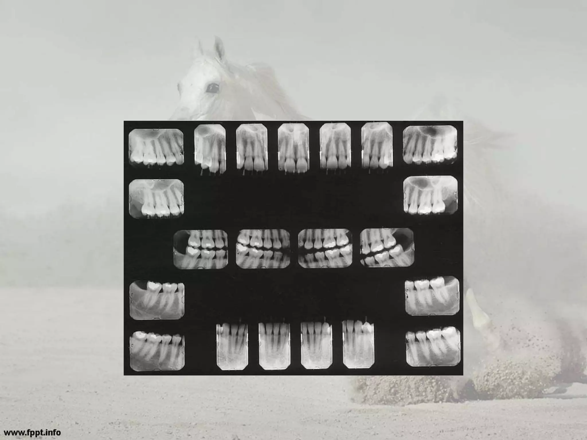
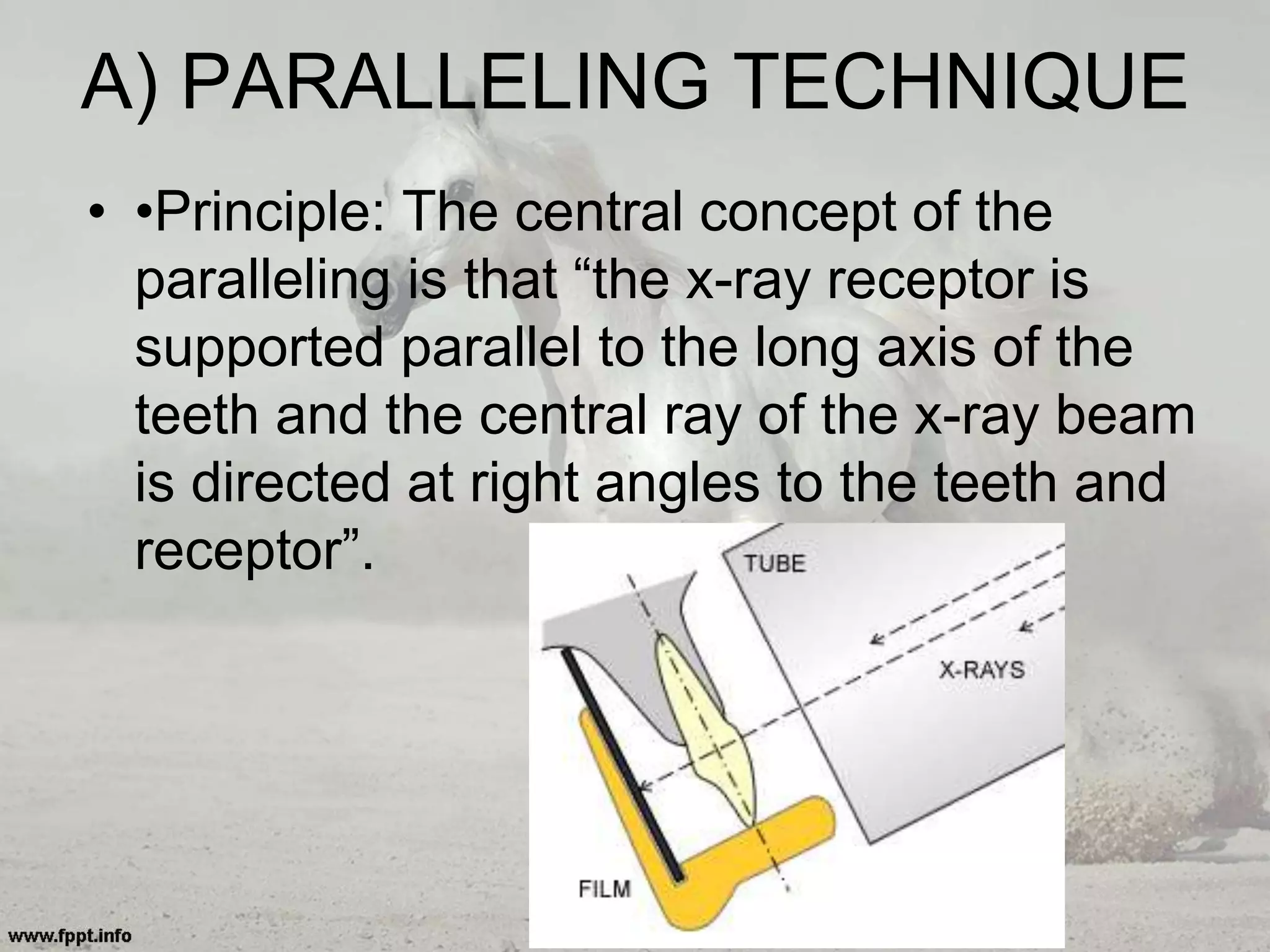
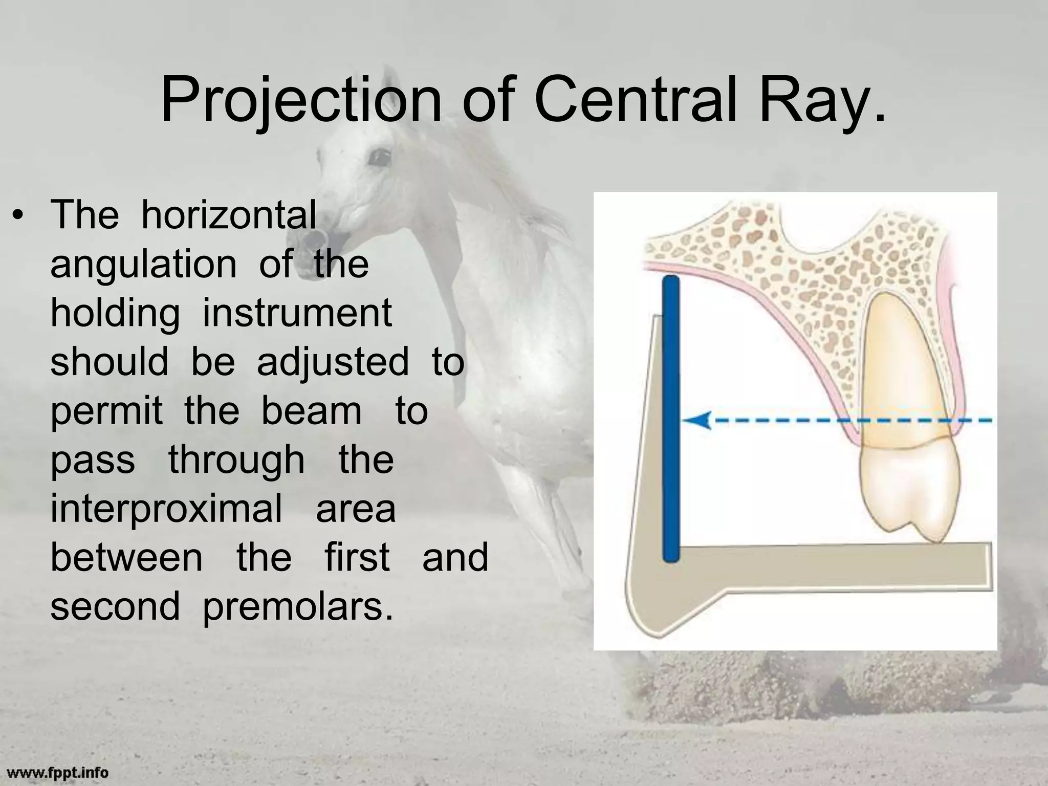
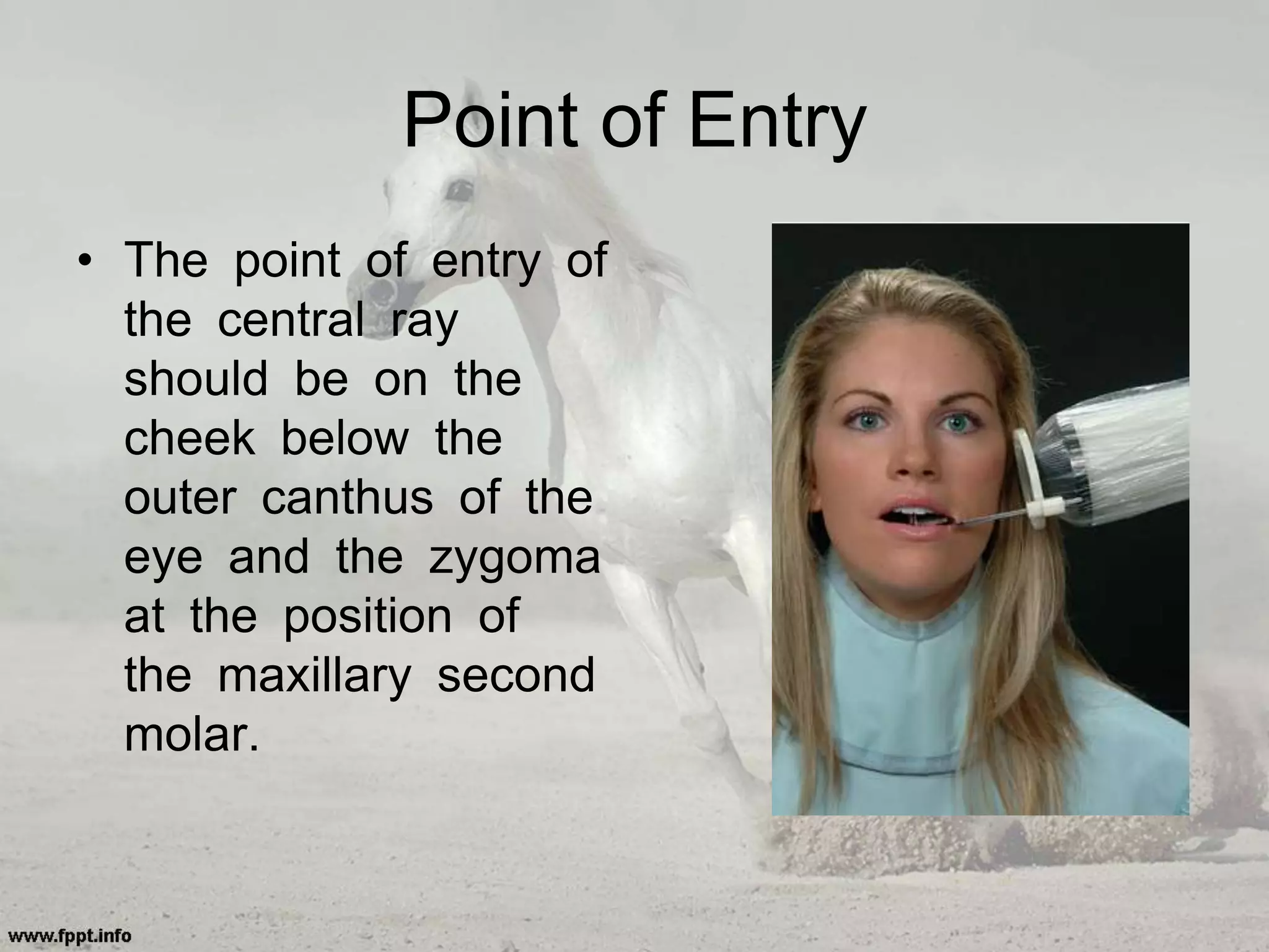
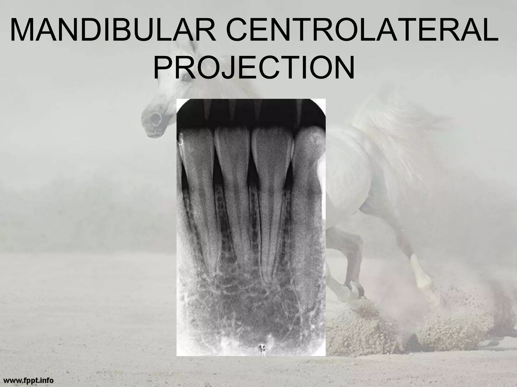
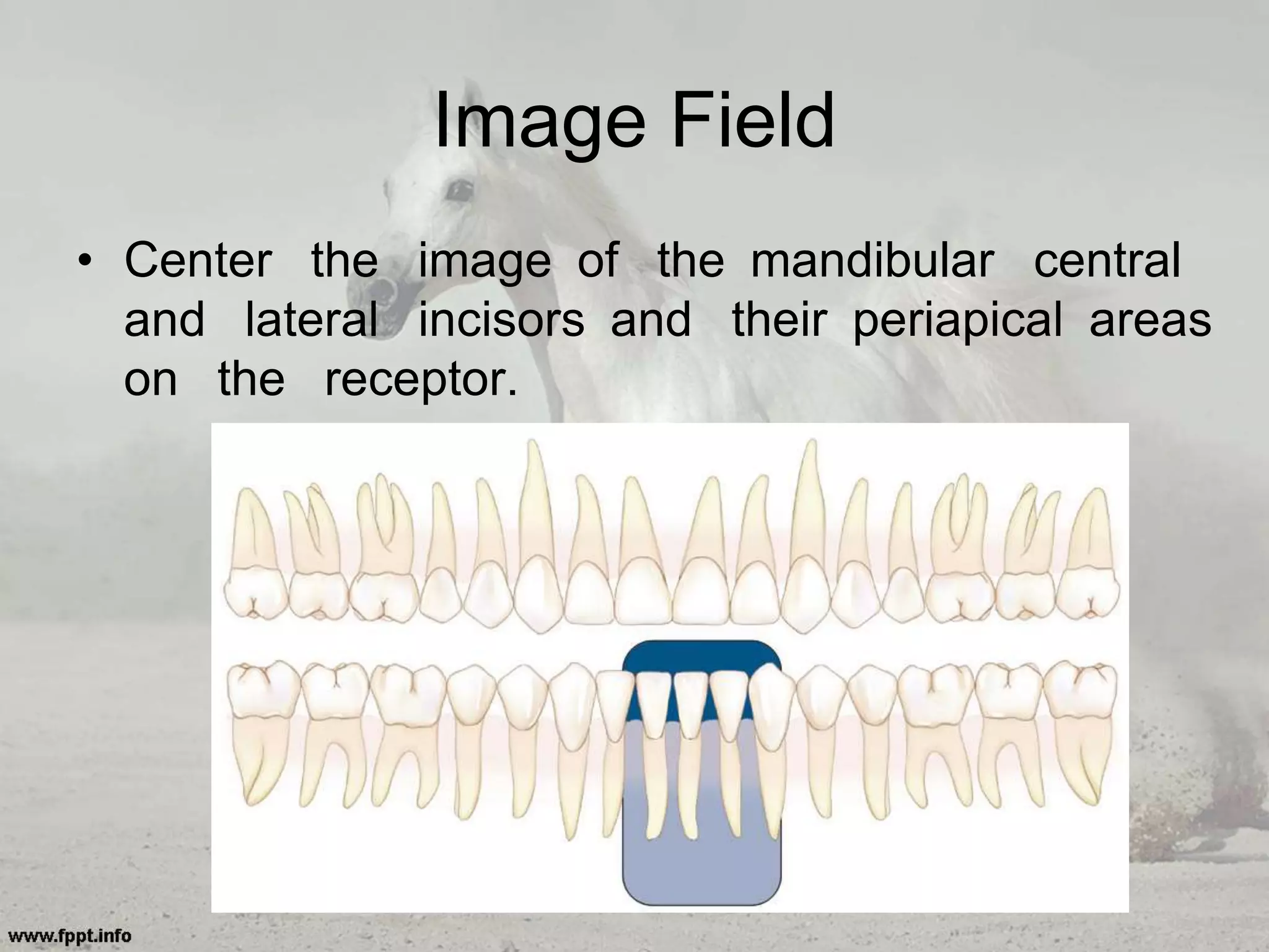
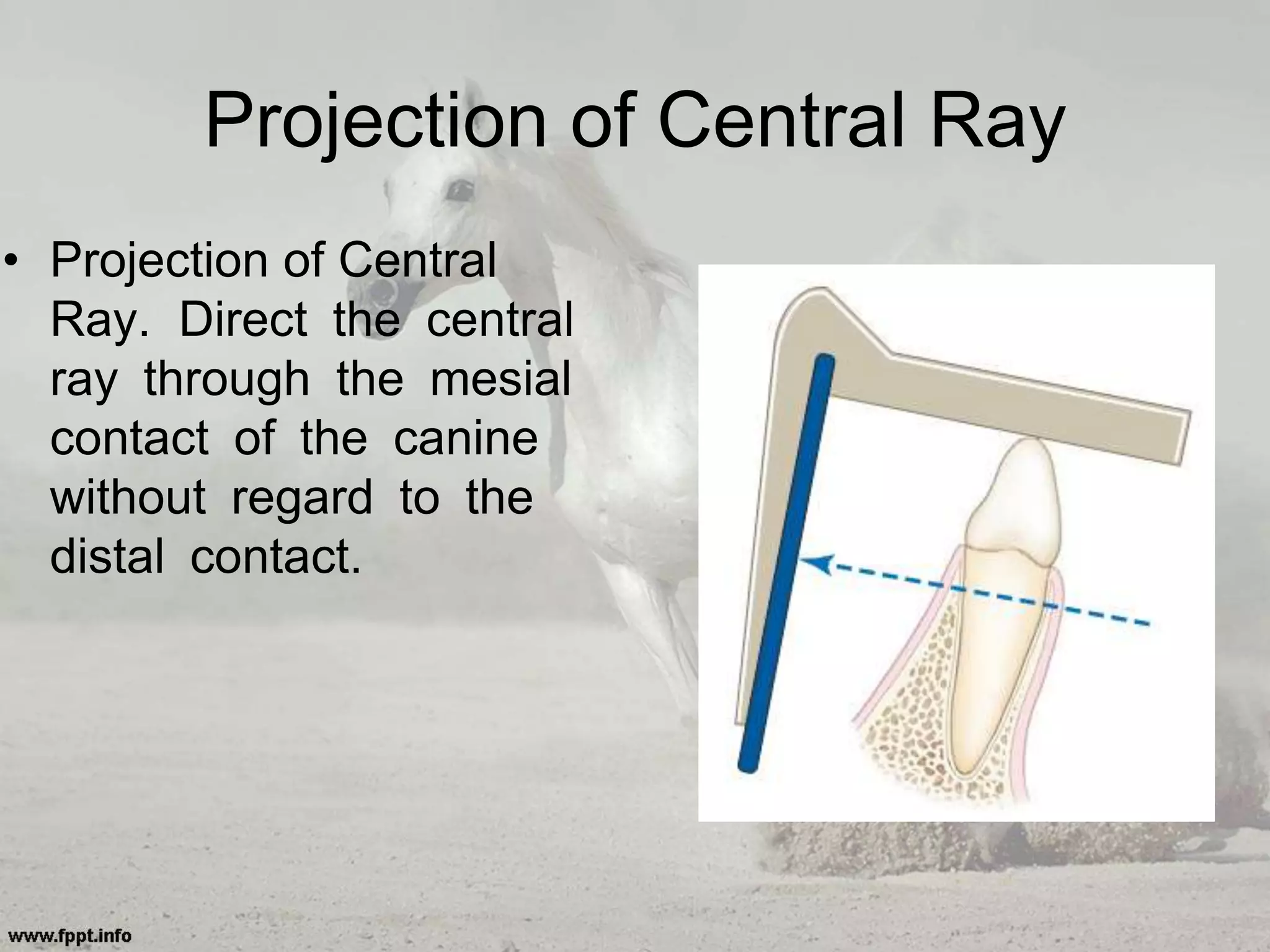
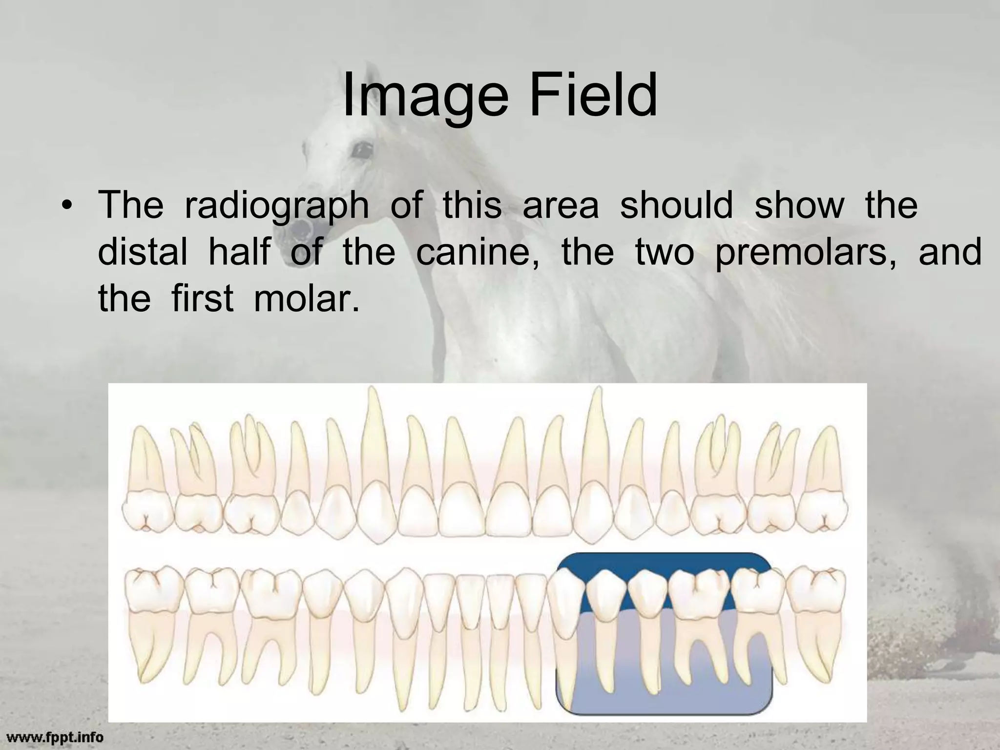
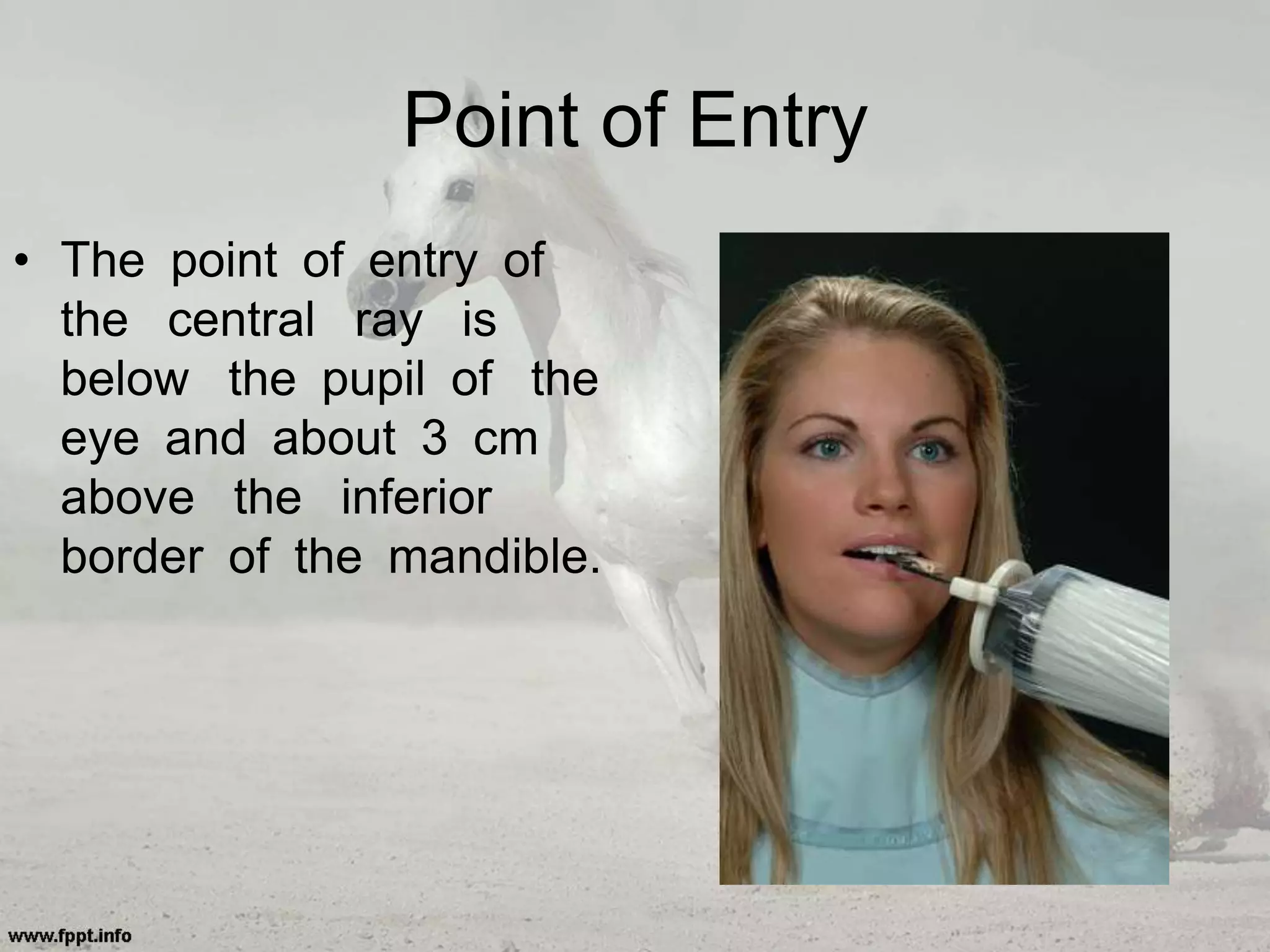
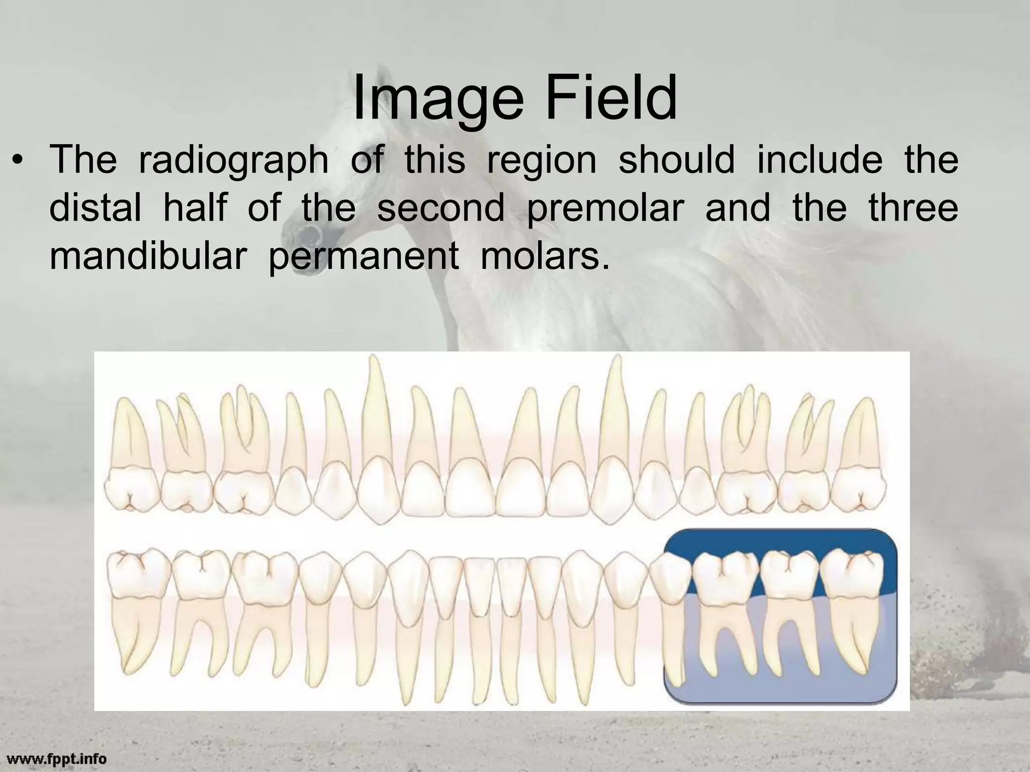
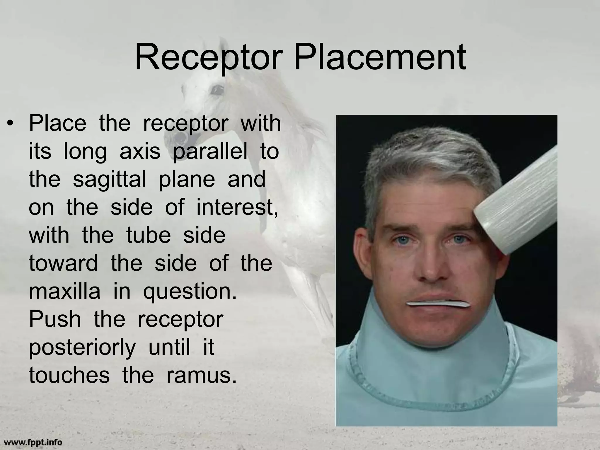
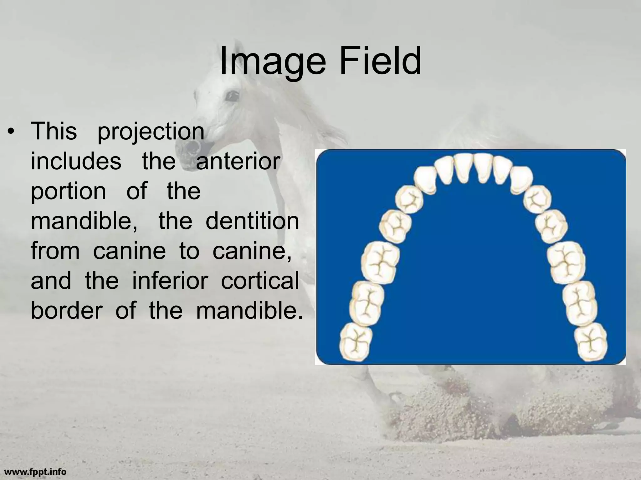
2. Intraoral images can be divided
into three categories:
ā¢ (1) periapical projections
ā¢ should show all of a tooth, including the
surrounding bone.
ā¢ (2) bitewing projections
ā¢ show only the crowns of teeth and the adjacent
ā¢ (3) occlusal projections.
ā¢ show an area of teeth and bone larger than
periapical images.
4. 1-Radiographs should record
the complete areas of interest
ā¢ the full length of the roots and at least 2 mm of
periapical bone must be visible.
ā¢ If evidence of a pathologic condition is present,
the area of the entire lesion plus some
surrounding normal bone should show on one
radiograph.
ā¢ Bitewing examinations should demonstrate
each posterior proximal surface at least once.
5. 2-Radiographs should have the
least possible amount of distortion.
ā¢ Most distortion is caused by improper
angulation of the x-ray beam rather than by the
curvature of the structures being examined or
inappropriate positioning of the receptor.
6. 3-Images should have optimal density
and contrast to facilitate interpretation.
ā¢ milliamperage (mA), peak kilovoltage
(kVp), and exposure time
ā¢ faulty processing
7. PERIAPICAL IMAGING
ā¢ To obtain a view of entire tooth and its
surrounding structures.
ā¢ 2 techniques:
paralleling technique (preferred)
bisecting technique
ā¢Paralleling technique:
less image distortion, reduces excess
radiation
ā¢
8. ā¢ Bisecting technique :
ā¢ for patients unable to accommodate the
positioning of paralleling technique, low
palatal vaults and children
9. GENERAL STEPS FOR
MAKING AN EXPOSURE
ā¢ Prepare unit for exposure.
ā¢ Greet and seat the patient.
ā¢ Adjust the x-ray unit setting.
ā¢ Wash hands thoroughly.
ā¢ Examine the oral cavity.
ā¢ Position the tube head.
ā¢ Position the receptor.
ā¢ Position the x-ray tube.
ā¢ Make the exposure.
10.
11. A) PARALLELING TECHNIQUE
ā¢ ā¢Principle: The central concept of the
paralleling is that āthe x-ray receptor is
supported parallel to the long axis of the
teeth and the central ray of the x-ray beam
is directed at right angles to the teeth and
receptorā.
12. Benefits:
ā¢ This orientation of the receptor, teeth, and
central ray minimizes geometric distortion and
presents the teeth and supporting bone in their
true anatomic relationships.
ā¢ The use of a long source-to-object distance
reduces the apparent size of the focal spot,
thus increasing image sharpness, and provides
images with minimal magnification.
14. Modifications
If the lack of parallelism does
not exceed 20, the radiograph
is generally acceptable.Ģ
Place 1 or 2 cotton rolls on bite
block.
Increase the vertical angulation
by 5 to 15 degrees
Shallow
palate
15. Modifications
For maxilla, place the
film on far side of the
film.
For mandible, place
film between the tori
and tongue
Bony
growths
17. ā¢ The bisecting-angle technique is based on
a simple geometric theorem, Cieszynski ā
s rule of isometry, which states that two
triangles are equal when they share one
complete side and have two equal angles.
18. Receptor-Holding Instruments
ā¢ It is undesirable to have the patient
support the receptor from the lingual
surface with his or her forefinger.
ā¢ Patients often use excessive force and
bend the receptor, causing distortion of the
image.
19. Positioning of the Patient
ā¢ For images of the maxillary arch, the patientās
head should be positioned upright with the
sagittal plane vertical and the occlusal plane
horizontal.
ā¢ For mandibular teeth are to be radiographed,
the head is tilted back slightly to compensate
for the changed occlusal plane when the mouth
is opened.
20. Receptor Placement
ā¢ The occlusal or incisal edge is oriented
against the teeth with an edge of the
receptor extending just beyond the teeth.
ā¢ If necessary for the patientās comfort, the
anterior corner of a film can be softened
by bending it before it is placed against the
mucosa. Care
21. Angulation of the Tube Head
ā¢ 1) Horizontal Angulation.
ā¢ the radiation beam is also centered on the
receptor. This angulation usually is at right angles
(in the horizontal projection) to the buccal or facial
surfaces of the teeth in each region.
ā¢ 2) Vertical Angulation.
ā¢ the clinicianās goal is to aim the central ray of the
x-ray beam at right angles to a plane bisecting the
angle between the receptor and the long axis of
the tooth.
22. ā¢ Excessive vertical angulation results in
foreshortening of the image.
ā¢ insufficient vertical angulation results in
image elongation.
25. Image Field.
ā¢ The field of view on these radiographs
(shaded area) should include both central
incisors and their periapical areas.
26. Receptor Placement.
ā¢ receptor at about
the level of the
second premolars or
first molars to take
advantage of the
maximal palatal
height so that the
entire length of the
teeth can be
projected on it.
27. Projection of Central Ray
ā¢ . Because the axial
inclination of the
maxillary incisors is
about 15 to 20
degrees, the vertical
angulation of the
tube should be at
the same positive
angle. The tube
should have 0
horizontal angulation.
28. Point of Entry
ā¢ on the lip, in the
midline, just below
the septum of the
nostril.
30. Image Field.
ā¢ . Include the mesial interproximal area with the
distal aspect of the central incisor on the
radiograph so that no overlap is evident.
31. Receptor Placement
ā¢ Place a No. 1
receptor deep in the
oral cavity parallel
withthe long axis
and the mesiodistal
plane of the
maxillary lateral
incisor.
32. Projection of Central Ray.
ā¢ Direct the central ray
through the middle of
the lateral incisor, with
no overlapping of the
margins of the crowns
at the interproximal
space on its mesial
aspect. Do not attempt
to visualize the distal
contact with the canine.
33. Point of Entry
ā¢ Orient the central
ray to enter high on
the lip about 1 cm
from the midline.
35. Image Field.
ā¢ Open the mesial contact area. Ignore the distal
contact because it will be visualized on other
projections.
36. Receptor Placement.
ā¢ Receptor Placement.
Place a No. 1
receptor against the
palate, well away
from the palatal
surface of the
teeth. Orient the
receptor packet with
its anterior edge at
37. Projection of Central Ray.
ā¢ Position the holding
instrument so that it
directs the beam
through the mesial
contact of the
canine.
38. Point of Entry.
ā¢ . The point of entry
is at about the
intersection of the
ā¢ distal and inferior
borders of the ala of
the nose.
40. Image Field
ā¢ should include the images of the distal half of
the canine and the premolars, with room for at
least the first molar.
41. Receptor Placement.
ā¢ The packet should
also include the
premolars and the
first molar and
maybe the mesial
portion of the
second molar.
42. Projection of Central Ray.
ā¢ The horizontal
angulation of the
holding instrument
should be adjusted to
permit the beam to
pass through the
interproximal area
between the first and
second premolars.
45. Image Field
ā¢ The radiograph of this region should show
the images of the distal half of the second
premolar, the three maxillary permanent
molars, and some of the tuberosity.
47. Projection of Central Ray
ā¢ Adjust the horizontal
angulation of the
receptor-holding
instrument to direct
the beam at right
angles to the buccal
surfaces of the
molar teeth.
48. Point of Entry
ā¢ The point of entry of
the central ray
should be on the
cheek below the
outer canthus of the
eye and the zygoma
at the position of
the maxillary second
molar.
50. Image Field
ā¢ Center the image of the mandibular central
and lateral incisors and their periapical areas
on the receptor.
51. Receptor Placement
ā¢ Place the long
dimension of the No.
1 receptor vertically
behind the central and
lateral incisors with the
contact area centered
and the lower border
below the tongue.
52. Projection of Central Ray
ā¢ Orient the central
ray through the
interproximal space
between the central
and lateral incisors.
53. Point of Entry
ā¢ The central ray
enters below the
lower lip and about
1 cm lateral to the
midline.
55. Image Field
ā¢ This image should show the entire mandibular
canine and its periapical area. Open its mesial
contact area. The distal contact is included on
other projections.
56. Receptor Placement
ā¢ Place a No. 1 receptor
packet in the mouth
with its long dimension
vertical and the
canine in the midline
of the receptor.
57. Projection of Central Ray
ā¢ Projection of Central
Ray. Direct the central
ray through the mesial
contact of the canine
without regard to the
distal contact.
58. Point of Entry
ā¢ The point of entry is
nearly perpendicular to
the ala of the nose,
over the position of
the canine, and about
3 cm above the inferior
border of the mandible.
60. Image Field
ā¢ The radiograph of this area should show the
distal half of the canine, the two premolars, and
the first molar.
61. Receptor Placement.
ā¢ Bring the No. 2
receptor into the mouth
with its plane nearly
horizontal. Rotate the
lead edge to the floor
of the mouth between
the tongue and the
teeth with the anterior
border near the midline
of the canine. Place the
receptor
62. Projection of Central Ray
ā¢ Position the receptor-
holding instrument to
project the central ray
through the second
premolar-molar area.
The vertical angulation
should be small, nearly
parallel with the
occlusal plane.
63. Point of Entry
ā¢ The point of entry of
the central ray is
below the pupil of the
eye and about 3 cm
above the inferior
border of the mandible.
65. Image Field
ā¢ The radiograph of this region should include the
distal half of the second premolar and the three
mandibular permanent molars.
66. ā¢ In the case of an impacted third molar
or a pathologic condition distal to the
third molar, a distal oblique molar
projection or even additional extraoral
projections (panoramic or lateral ramus)
may be required to demonstrate the
area adequately.
ā¢ If the molar area is edentulous, place
the receptor far enough posterior to
include the retromolar area in the
examination.
67. Receptor Placement
ā¢ Place the No. 2
receptor in the mouth
with its plane nearly
horizontal. Rotate the
inferior edge downward
beneath the lateral
border of the tongue,
displacing it medially.
68. Projection of Central Ray
ā¢ Projection of Central
Ray. Proper
placement of the
holding instrument
directs the central
ray through the
second molar.
ā¢ Adjust the horizontal
angulation to project
the beam through
the contact areas.
69. Point of Entry
ā¢ Direct the point of
entry of the central
ray below the outer
canthus of the eye
about 3 cm above
the inferior border of
the mandible
70. ā¢ Bitewing (also
called
interproximal )
radiographs
include the
crowns of the
maxillary and
mandibular teeth
and the alveolar
crest on the
same receptor.
Bitewing (interproximal)
71. ā¢ interproximal caries in the early stages.
ā¢ secondary caries below restorations.
ā¢ Overhanging restorations.
ā¢ evaluating the periodontal
condition.(alveolar bone crest)
ā¢ detecting calculus deposits.
Indications
72. ā¢ Parallel with the occlusal plane.
ā¢ The aiming cylinder is positioned about +7
to +10 degrees to project the beam
parallel with the occlusal plane.
Vertical
Bitewing
Horizontal
Bitewing
76. Image Field
ā¢ This projection should cover the distal portion of
the mandibular canine anteriorly and show equally
the crowns of the maxillary and mandibular
premolar teeth.
77. Receptor Placement
ā¢ Place the receptor
between the tongue
and the teeth, far
enough from the lingual
surface of the teeth to
prevent interference by
the palate on closing
and parallel to the long
axes of the teeth. The
anterior border of the
receptor
78. Projection of Central Ray.
ā¢ Projection of Central
Ray. Adjust the
horizontal angulation
of the cone to
ā¢ project the central
ray to the center of
the receptor through
the premolar contact
areas.
79. ā¢ To compensate for the slight
inclination of the receptor against the
palatal mucosa, the vertical angulation
should be about +5 degrees. (In the
drawing, the mandibular teeth are
shown in dashed lines.)
80. Point of Entry
ā¢ Identify the point of
entry by retracting
the cheek and
determining that the
central ray will enter
the line of occlusion
at the point of
contact between the
second premolar and
the first molar.
82. Image Field
ā¢ This projection should show the distal surface of
the most posterior erupted molar and equally
the crowns of the maxillary and mandibular
molars.
83. Receptor Placement
ā¢ Receptor Placement.
Place the receptor
between the tongue
and teeth as far
lingual as practical to
avoid contacting the
sensitive attached
gingiva. The distal
margin of the receptor
should extend 1 to 2
mm beyond the most
posterior erupted molar.
84. Projection of Central Ray
ā¢ Project the central ray
to the center of the
receptor and through
the contact of the first
and second maxillary
molars.
85. ā¢ Angle the central ray slightly from
the anterior because the molar contacts
usually are not oriented at
ā¢ right angles to the buccal surfaces of
these teeth.
ā¢ A vertical angulation of +10 degrees is
recommended. (In the drawing, the
mandibular teeth are shown in dashed
lines.)
86. Point of Entry
ā¢ Point of Entry. The
central ray should
enter the cheek
below the lateral
canthus of the eye
at the level of the
occlusal plane.
87. ā¢ An occlusal radiograph displays a relatively
large segment of a dental arch.
ā¢ when patients are unable to open the mouth.
ā¢ localization of objects.
ā¢ To locate precisely roots and
supernumerary, unerupted, and impacted
teeth (this technique is especially useful for
impacted canines and third molars)
ā¢ To localize foreign bodies in the jaws and
stones in the ducts.
Occlusal View
88. ā¢ To demonstrate and evaluate the integrity
of the outlines of the maxillary sinus
ā¢ To demonstrate and evaluate the
integrity of the anterior, medial, and
lateral outlines of the maxillary sinus
ā¢ To determine the medial and lateral extent
of disease (e.g., cysts, osteomyelitis,
tumors) and to detect disease in the
palate or floor of the mouth.
90. Image Field
ā¢ The primary field of
this projection includes
the anterior maxilla
and its dentition and
the anterior floor of
the nasal fossa and
teeth from canine to
canine.
91. Receptor Placement
Adjust the patientās head
so that the sagittal plane
is perpendicular and the
occlusal plane is
horizontal to the floor.
92. ā¢ Place the receptor in the mouth with the
exposure side toward the maxilla, the
posterior border touching the rami, and the
long dimension of the receptor
perpendicular to the sagittal plane.
ā¢ The patient stabilizes the receptor by gently
closing the mouth or using gentle bilateral
thumb pressure.
93. ā¢ Projection of Central Ray. Orient the
central ray through the tip of the
nose toward the middle of the
receptor with approximately +45 degrees
vertical angulation and 0 degrees
horizontal angulation.
ā¢ Point of Entry. The central ray enters
the patientās face approximately through
the tip of the nose.
95. Image Field
ā¢ This projection shows
the palate, zygomatic
processes of the
maxilla, anteroinferior
aspects of each
antrum, nasolacrimal
canals, teeth from
second molar to
second molar, and
nasal septum.
96. Receptor Placement
ā¢ Seat the patient
upright with the
sagittal plane
perpendicular to the
floor and the occlusal
plane horizontal.
97. ā¢ Place the receptor, with its long dimension
perpendicular to the sagittal plane, crosswise
in the mouth. Gently push the receptor in
backward until it contacts the anterior
border of the mandibular rami. The patient
stabilizes the receptor by gently closing the
mouth.
98. ā¢ Projection of Central Ray. Direct the
central ray at a vertical angulation of
+65 degrees and a horizontal angulation
of 0 degrees to the bridge of the nose
just below the nasion, toward the
middle of the receptor.
ā¢ Point of Entry. Generally, the central
ray enters the patientās face through the
bridge of the nose.
100. Image Field
ā¢ This projection shows a
quadrant of the
alveolar ridge of the
maxilla, inferolateral
aspect of the antrum,
tuberosity, and teeth
from the lateral incisor
to the contralateral
third molar.
101. Receptor Placement
ā¢ Place the receptor with
its long axis parallel to
the sagittal plane and
on the side of interest,
with the tube side
toward the side of the
maxilla in question.
Push the receptor
posteriorly until it
touches the ramus.
102. ā¢ Position the lateral border parallel with
the buccal surfaces of the posterior
teeth, extending laterally approximately
1 cm past the buccal cusps. Ask the
patient to close gently to hold the
receptor in position.
103. ā¢ Projection of Central Ray. Orient the
central ray with a vertical angulation of +60
degrees, to a point 2 cm below the lateral
canthus of the eye, directed toward the
center of the receptor.
ā¢ Point of Entry. The central ray enters at a
point approximately 2 cm below the lateral
canthus of the eye.
105. Image Field
ā¢ This projection
includes the anterior
portion of the
mandible, the dentition
from canine to canine,
and the inferior cortical
border of the mandible.
106. Receptor Placement
ā¢ Seat the patient tilted
back so that the occlusal
plane is 45 degrees
above horizontal.
ā¢ Place the receptor in the
mouth with the long axis
perpendicular to the
sagittal plane and push it
posteriorly until it touches
the rami.
107. ā¢ Projection of Central Ray. Orient the central
ray with ā10 degrees angulation through
the point of the chin toward the middle of
the receptor; this gives the ray ā55 degrees
of angulation to the plane of the receptor.
ā¢ Point of Entry. The point of entry of the
central ray is in the midline and through the
tip of the chin.
109. Image Field
ā¢ This projection includes
the soft tissue of the
floor of the mouth and
reveals the lingual
and buccal plates of
the mandible from
second molar to
second molar.
110. ā¢ When this view is made to examine the
floor of the mouth (e.g., for sialoliths),
the exposure time should be reduced to
half the time used to create an image
of the mandible.
111. Receptor Placement
ā¢ Seat the patient in a
semireclining position
with the head tilted
back so that the ala-
tragus line is almost
perpendicular to the
floor.
112. ā¢ Place the receptor in the mouth with
its long axis perpendicular to the
sagittal plane and with the tube side
toward the mandible.
ā¢ The anterior border of the receptor
should be approximately 1 cm
beyond the mandibular central incisors.
ā¢ Ask the patient to bite gently on the
receptor to hold it in position.
113. ā¢ Projection of Central Ray. Direct the
central ray at the midline through the floor
of the mouth approximately 3 cm below the
chin, at right angles to the center of the
receptor.
ā¢ Point of Entry. The point of entry of the
central ray is in the midline through the floor
of the mouth approximately 3 cm below the
chin.
115. Image Field
ā¢ Image Field. This
projection covers the
soft tissue of half the
floor of the mouth, the
buccal and lingual
cortical plates of half of
the mandible, and the
teeth from the lateral
incisor to the
contralateral third
molar.
116. Receptor Placement.
ā¢ Seat the patient in a semireclining position with
the head tilted back so that the ala-tragus line is
almost perpendicular to the floor. Place the
receptor in the mouth with its long axis initially
parallel with the sagittal plane and with the
pebbled side down toward the mandible
117. ā¢ Projection of Central Ray. Direct the
central ray perpendicular to the center
of the receptor through a point
beneath the chin, approximately 3 cm
posterior to the point of the chin and 3
cm lateral to the midline.
ā¢ Point of Entry. The point of entry of
the central ray is beneath the chin,
approximately 3 cm posterior to the
chin and approximately 3 cm lateral to
the midline.
119. ā¢ Radiation protection is most important for
children because of their greater sensitivity
to irradiation.
ā¢ The best way to reduce unnecessary
exposure is for the dentist to make the
minimal number of receptors required for
the individual patient. These
120. ā¢ The frequency should be determined
partly by the patientās caries rate.
ā¢ The relatively shallow palate and floor of
the mouth may require further modification
of receptor placement.
121. EXAMINATION COVERAGE
ā¢ Also, an exposure appropriate to the
childās size should be used.
ā¢ example, a 50% reduction in the mA used
for an average young adult gives the
proper density for patients younger than
10 years.
122. Primary Dentition (3 to 6 Years)
ā¢ This examination may consist of two
anterior occlusal receptors, two posterior
bitewing receptors, and up to four
posterior periapical receptors as indicated
123. 1- Maxillary Anterior Occlusal
Projection.
ā¢ A No. 2 receptor
ā¢ its long axis perpendicular to the sagittal plane
and the pebbled surface toward the maxillary
teeth.
ā¢ central ray is directed at a vertical angulation of
+60 degrees through the tip of the nose toward
the center of the receptor.
124. 2- Mandibular Anterior Occlusal
Projection
ā¢ A No. 2 receptor
ā¢ occlusal plane is about 25 degrees above
the plane of the floor.
ā¢ The central ray is oriented at ā30 degrees
vertical angulation and through the tip of
the chin toward the receptor.
125. 3- Bitewing Projection
ā¢ A No. 0 receptor
ā¢ The image field :the distal half of the
canine and the deciduous molars.
ā¢ A positive vertical angulation of +5 to +10
ā¢ The horizontal angle :direct the beam
through the interproximal spaces.
126. 4- Deciduous Maxillary Molar
Periapical Projection
ā¢ A No. 0 receptor
ā¢ The image field of this projection should
include the distal half of the primary canine
and both primary molars.
127. 5- Deciduous Mandibular Molar
Projection.
ā¢ A No. 0 receptor
ā¢ The exposed radiograph should show the
distal half of the mandibular primary
canine and the primary molar teeth.
128. Mixed Dentition (7 to 12 Years)
ā¢ A complete examination of the mixed
dentition, consists of
ā¢ two incisor periapical views, four canine
periapical views, four posterior periapical
views, and two or four posterior
129. ā¢ For the maxillary and interproximal projections,
the child should be seated upright with the
sagittal plane perpendicular and the occlusal
plane parallel to the floor.
ā¢ For the mandibular projections, the child should
be seated upright with the sagittal plane
perpendicular and the ala-tragus line parallel to
the floor. XC
130. 1- Maxillary Anterior Periapical
Projection
ā¢ A No. 1 receptor
ā¢ centered on the
embrasure between the
central incisors in the
131. 2- Mandibular Anterior
Periapical Projection
ā¢ A No. 1 receptor
ā¢ positioned behind the
mandibular central and
lateral incisors.
132. 3- Canine Periapical Projection
ā¢ A No. 1 receptor should be positioned
behind each of the canines.
133. 4- Deciduous and Permanent
Molar Periapical Projection
ā¢ A No. 1 or No. 2 receptor (if the child is
large enough)
ā¢ should be positioned with the anterior
edge behind the canine.
134. 5- Posterior Bitewing Projection.
ā¢ No. 1 or No. 2 receptor
ā¢ Four bitewing projections should be
exposed when the second permanent
molars have erupted.
135. MOBILE IMAGING
ā¢ This machine uses a high-frequency, constant
potential x-ray generator (60 kilowatt constant
potential)
ā¢ short focal spot-to-skin
ā¢ small focus spot (0.4 mm).
136. operator dose
ā¢ The operator dose is mitigated by the use of
1- internal shielding materials in the unit to reduce
leakage exposure
2- and a shield on the aiming cylinder to minimize
backscatter from the patient.
138. INFECTION
ā¢ Infection in the orofacial structures may result in
edema and lead to trismus of some of the
muscles of mastication. As a result, intraoral
radiography may be painful to the patient and
difficult for both the patient and the radiologist.
ā¢ Under such circumstances, extraoral or
occlusal techniques may offer the only
possibility of an examination.
139. ā¢ In the case of edema in an area to be
examined, exposure time should be
increased to compensate for the tissue
swelling.
140. TRAUMA
ā¢ Dental fractures are best appreciated by
using periapical or occlusal radiographs.
Special care must be taken when making
these views because of the condition of
the patient.
ā¢ Skeletal fractures are usually best seen
with panoramic or other extraoral views or
a computed tomography examination.
141. PATIENTS WITH MENTAL
DISABILITIES
ā¢ When the radiographic examination is
performed speedily, unpredictable moves
by the patient can be minimized.
ā¢ In some cases, sedation may be required.
142. PATIENTS WITH PHYSICAL
DISABILITIES
ā¢ These patients usually are cooperative and
eager to assist.
ā¢ Members of the patientās family often are very
helpful in assisting the patient into and out of
the examination chair and in receptor
positioning and holding, inasmuch as they
usually are familiar with the patientās condition
and accustomed to coping with it.
143. GAG REFLEX
ā¢ the radiologist should make an effort to
relax
ā¢ The gag reflex often is worse when a
patient is tired.
ā¢ Stimulating the posterior dorsum of the
tongue or the soft palate usually initiates
the gag reflex.
ā¢ Sliding the film, along the palate or tongue
is likely to stimulate the gag reflex.
144. ā¢ In extreme cases, topical anesthetic agents in
mouthwashes or spray can be administered to
produce temporary numbness of the tongue
and palate to reduce gagging.
ā¢ The most effective approach is to reduce
apprehension, minimize tissue irritation, and
encourage rapid breathing through the nose.
145. IMAGING FOR ENDODONTICS
ā¢ In these cases, when it is necessary to
separate the roots on multirooted teeth, a
second projection may be made. The horizontal
angulation is altered 20 degrees mesially for
maxillary premolars, 20 degrees mesially or
distally for maxillary molars, or 20 degrees
distally for an oblique projection of mandibular
molar roots.
146. ā¢ If a sinus tract is encountered, its course is
tracked by threading a No. 40 gutta percha
cone through the tract before the radiograph is
made.
148. EDENTULOUS PATIENTS
ā¢ To discover roots, residual infection, impacted
teeth, cysts, or other pathologic entities that
may adversely affect the usefulness of
prosthetic appliances or the patientās health.
ā¢ After a determination has been made that these
entities are not present, repeated examinations
to detect them are not warranted in the absence
of signs or symptoms.
149. ā¢ If available, a panoramic examination of
the edentulous jaws is most convenient.
ā¢ If panoramic equipment is unavailable, an
examination consisting of 14 intraoral
views provides an excellent survey.
150. ā¢ . The exposure required for an edentulous ridge
is approximately 25% less than that for a
dentulous ridge.
ā¢ This examination consists of seven projections
in each jaw (adult No. 2 receptor) as follows:
ā¢ Central incisors (midline): one projection
ā¢ Lateral canine: two projections
ā¢ Premolar: two projections
ā¢ Molar: two projections