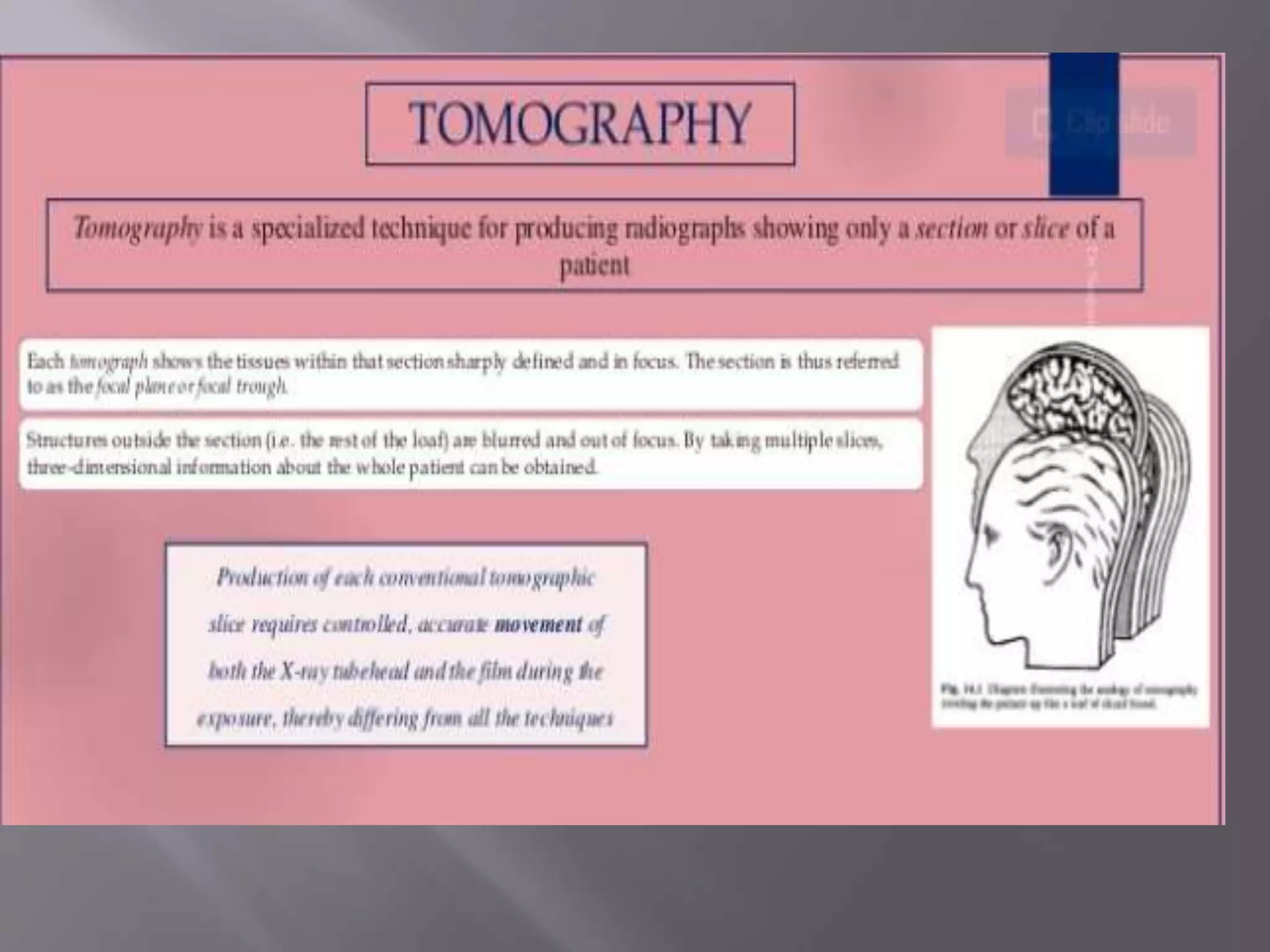
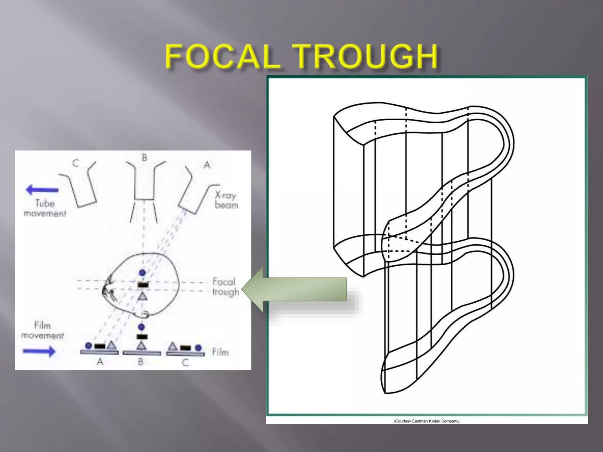
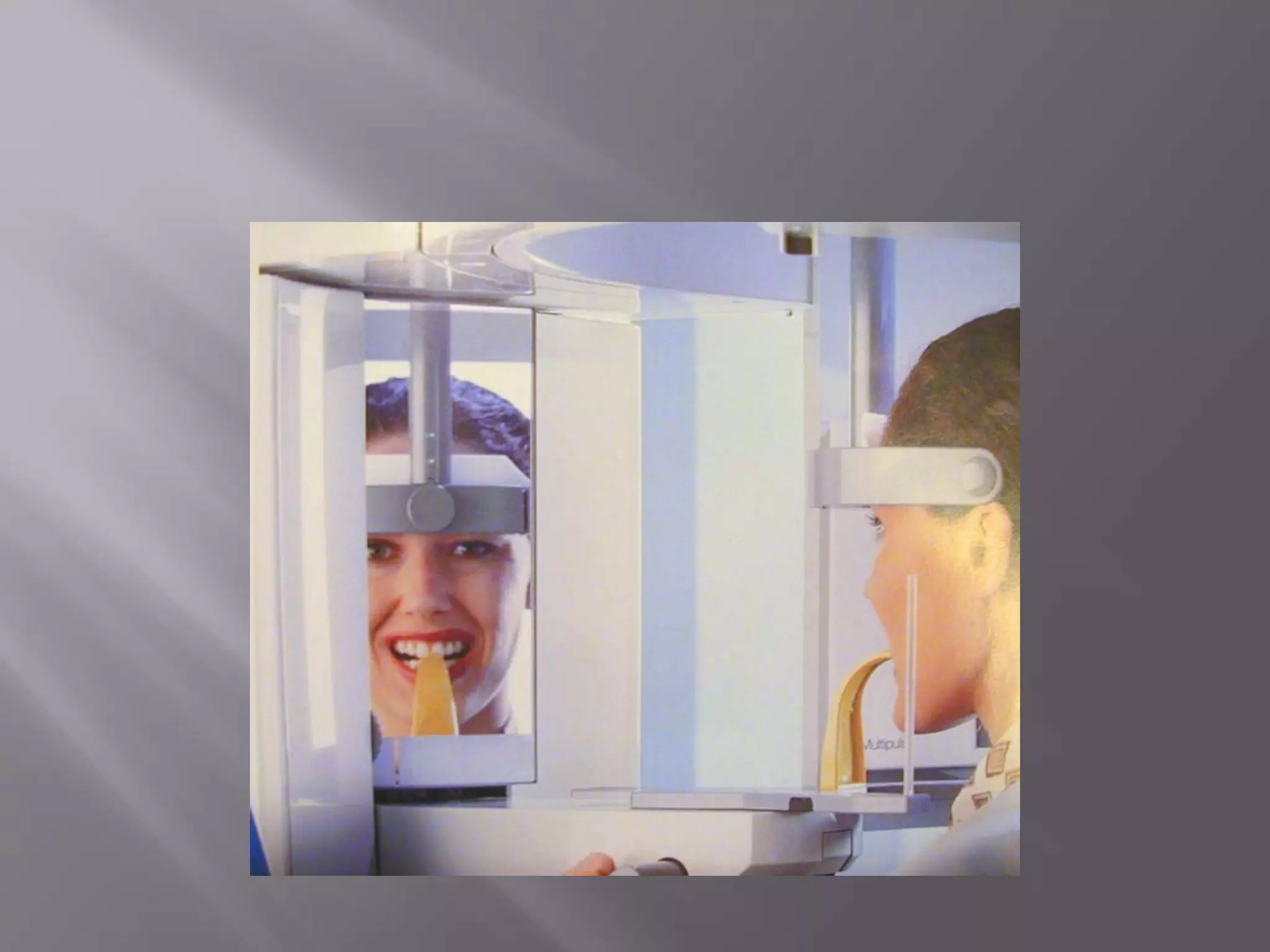
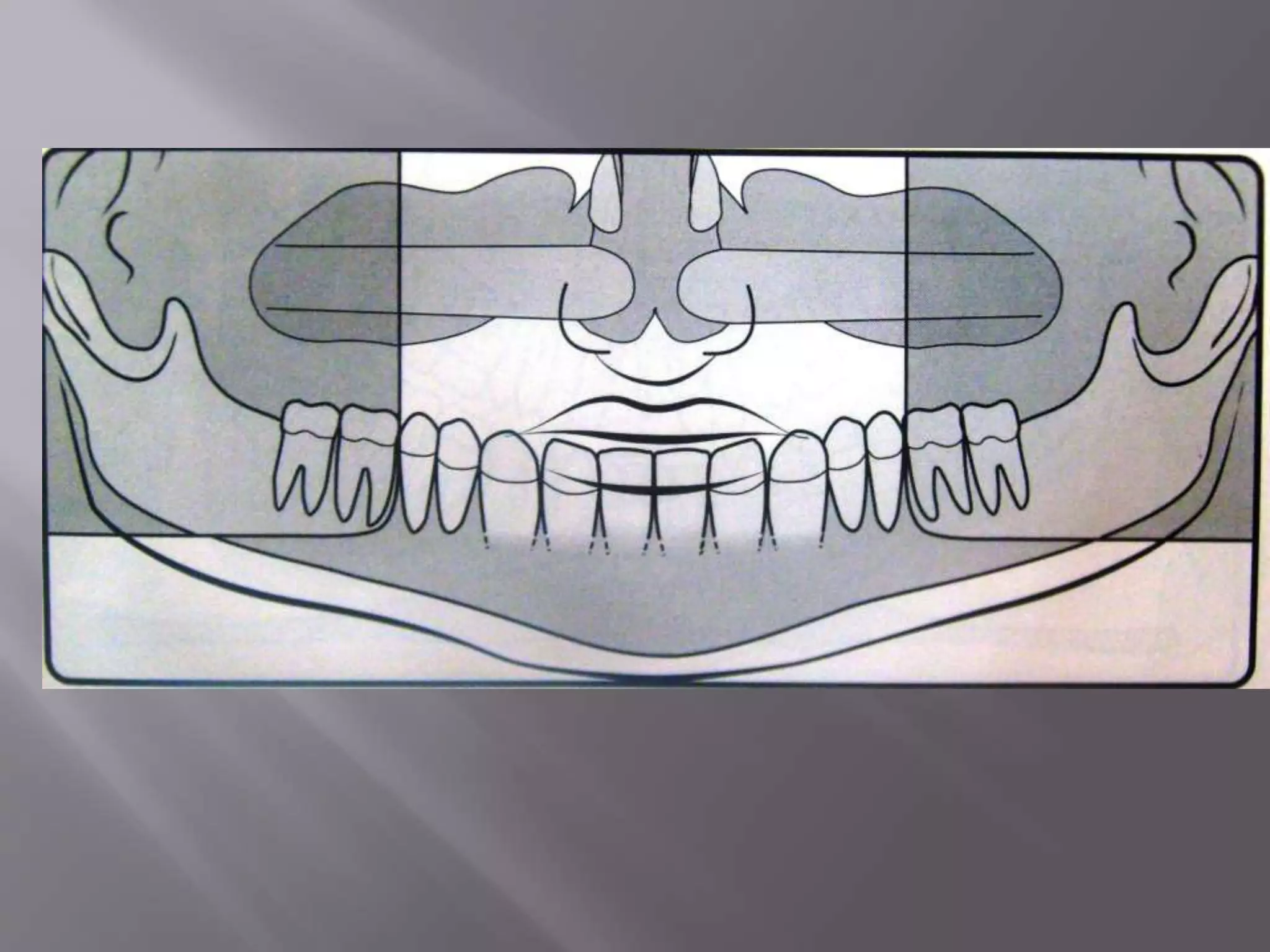
Panoramic imaging, also called pantomography, produces a single tomographic image of the maxillary and mandibular dental arches and their supporting structures. It is used to evaluate impacted teeth, eruption patterns, lesions, trauma, periodontal bone loss, and more. Panoramic imaging works by having an x-ray source and image receptor rotate around the patient's head, capturing structures within the focal trough sharply while blurring structures outside of it. Positioning the patient correctly is important for diagnostic image quality.
brief description about CONTENTS Introduction Principles of panoramic imaging Image layer Panoramic machines Panoramic film Patient positioning Interpreting the panoramic imaging INDICATION Advantages Disadvantages Conclusion References
3. INTRODUCTION • Panoramic imaging also called pantomography is a technique for producing a single tomographic image of facial structures that includes both the maxillary and mandibular dental arches and their supporting structures . • This is a curvilinear variant of conventional tomography.
4. PRINCIPLES OF PANORAMIC IMAGE FORMATION • Patero and Numata - describe the principles of panoramic radiography • based on the principle of reciprocal movement of x-ray source and an image receptor around a central point or plane called the image layer, in which the OBJECT of image is located. • OBJECT in front or behind this image are not clearly captured because of their movement relative to the centre of rotation of the receptor and the x-ray source.
5. The film and x-ray tubehead move around the patient in opposite directions in panoramic radiography
6. ROTATION CENTER The pivotal point or axis around which the cassette carrier and tube head rotate is termed rotation center Three basic rotation center used in panoramic radiography Double centre rotation Triple centre rotation moving centre rotation The location and number of rotational centers INFLUENCE size and shape of focal trough
7. IMAGE LAYER • Also known as focal trough • It is a three dimensional curved zone where the structures lying within this layer are reasonably well defined on final panoramic image. • The structures seen on a panoramic image are primarily those located within image layer. • OBJECTSoutside the image layer are blurred magnified are reduced in size. Even distorted to the extent of not being recognizable. • This shape of image layer varies with the brand of equipment used.
8. FOCAL TROUGH
9. FACTORS AFFECTING SIZE OF IMAGE LAYER: Arc path Velocity of receptor and X-ray tube head Alignment of x-ray beam Collimator width The location of image layer change with extensive machine used so recalibration may be necessary if consistently suboptimal images are produced. As a position of object is moved within the image layer size and shape of image layer change.
10. PANORAMIC UNIT
11. A, Orthophos XG Plus extraoral x-ray machine. B, Orthoralix 8500 extraoral x-ray machine. C, Example of a digital panoramic system
12. PARTS OF PANORAMIC UNITS a. x-ray tube head b. head positioner: chin rest notched bite block forehead rest lateral head support c. exposure controls
13. X-RAY TUBE HEAD: • Similar to intraoral x-ray tube head • Each has a filament to produce electrons and a target to produce x-rays • Collimator is a lead plate with narrow vertical slit • Narrow x-ray beam emerges from collimator minimize patient exposure to radiation
1
IDEAL IMAGE CHARACTERISTICS
FACTORS RELATED TO THE RADIATION BEAM
FACTORS RELATED TO THE OBJECT
FACTORS RELATED TO THE TECHNIQUE
FACTORS RELATED TO RECORDING OF THE ROENTGEN IMAGE OF THE OBJECT
DARK/ LIGHT IMAGE IDEAL IMAGE
IDEAL QUALITY CRIETRIA
this contains the occlusal radiography methods for both maxillary and mandibular different occusal radiographic techniques, principles, classification, indications
Paralleling and bisecting radiographic techniquesDr. Ritu Gupta
this is the seminar for Undergraduate students consisting of initial paralellelig and bisecting radiographic techniques, history, types, size, extraoral films, technical errors, radiographic examination in special children
This is a presentation describing in brief regarding the physics behind MRI and it's application from dental point of view. It contains few videos as well.
this slide briefs the correct positioning and some error in OPG and lateral cephalometric imaging. It also briefs the importance of correct positioning from the perspective of the maxillofacial surgeon.
Title: Sense of Taste
Presenter: Dr. Faiza, Assistant Professor of Physiology
Qualifications:
MBBS (Best Graduate, AIMC Lahore)
FCPS Physiology
ICMT, CHPE, DHPE (STMU)
MPH (GC University, Faisalabad)
MBA (Virtual University of Pakistan)
Learning Objectives:
Describe the structure and function of taste buds.
Describe the relationship between the taste threshold and taste index of common substances.
Explain the chemical basis and signal transduction of taste perception for each type of primary taste sensation.
Recognize different abnormalities of taste perception and their causes.
Key Topics:
Significance of Taste Sensation:
Differentiation between pleasant and harmful food
Influence on behavior
Selection of food based on metabolic needs
Receptors of Taste:
Taste buds on the tongue
Influence of sense of smell, texture of food, and pain stimulation (e.g., by pepper)
Primary and Secondary Taste Sensations:
Primary taste sensations: Sweet, Sour, Salty, Bitter, Umami
Chemical basis and signal transduction mechanisms for each taste
Taste Threshold and Index:
Taste threshold values for Sweet (sucrose), Salty (NaCl), Sour (HCl), and Bitter (Quinine)
Taste index relationship: Inversely proportional to taste threshold
Taste Blindness:
Inability to taste certain substances, particularly thiourea compounds
Example: Phenylthiocarbamide
Structure and Function of Taste Buds:
Composition: Epithelial cells, Sustentacular/Supporting cells, Taste cells, Basal cells
Features: Taste pores, Taste hairs/microvilli, and Taste nerve fibers
Location of Taste Buds:
Found in papillae of the tongue (Fungiform, Circumvallate, Foliate)
Also present on the palate, tonsillar pillars, epiglottis, and proximal esophagus
Mechanism of Taste Stimulation:
Interaction of taste substances with receptors on microvilli
Signal transduction pathways for Umami, Sweet, Bitter, Sour, and Salty tastes
Taste Sensitivity and Adaptation:
Decrease in sensitivity with age
Rapid adaptation of taste sensation
Role of Saliva in Taste:
Dissolution of tastants to reach receptors
Washing away the stimulus
Taste Preferences and Aversions:
Mechanisms behind taste preference and aversion
Influence of receptors and neural pathways
Impact of Sensory Nerve Damage:
Degeneration of taste buds if the sensory nerve fiber is cut
Abnormalities of Taste Detection:
Conditions: Ageusia, Hypogeusia, Dysgeusia (parageusia)
Causes: Nerve damage, neurological disorders, infections, poor oral hygiene, adverse drug effects, deficiencies, aging, tobacco use, altered neurotransmitter levels
Neurotransmitters and Taste Threshold:
Effects of serotonin (5-HT) and norepinephrine (NE) on taste sensitivity
Supertasters:
25% of the population with heightened sensitivity to taste, especially bitterness
Increased number of fungiform papillae
Explore natural remedies for syphilis treatment in Singapore. Discover alternative therapies, herbal remedies, and lifestyle changes that may complement conventional treatments. Learn about holistic approaches to managing syphilis symptoms and supporting overall health.
- Video recording of this lecture in English language: https://youtu.be/lK81BzxMqdo
- Video recording of this lecture in Arabic language: https://youtu.be/Ve4P0COk9OI
- Link to download the book free: https://nephrotube.blogspot.com/p/nephrotube-nephrology-books.html
- Link to NephroTube website: www.NephroTube.com
- Link to NephroTube social media accounts: https://nephrotube.blogspot.com/p/join-nephrotube-on-social-media.html
Title: Sense of Smell
Presenter: Dr. Faiza, Assistant Professor of Physiology
Qualifications:
MBBS (Best Graduate, AIMC Lahore)
FCPS Physiology
ICMT, CHPE, DHPE (STMU)
MPH (GC University, Faisalabad)
MBA (Virtual University of Pakistan)
Learning Objectives:
Describe the primary categories of smells and the concept of odor blindness.
Explain the structure and location of the olfactory membrane and mucosa, including the types and roles of cells involved in olfaction.
Describe the pathway and mechanisms of olfactory signal transmission from the olfactory receptors to the brain.
Illustrate the biochemical cascade triggered by odorant binding to olfactory receptors, including the role of G-proteins and second messengers in generating an action potential.
Identify different types of olfactory disorders such as anosmia, hyposmia, hyperosmia, and dysosmia, including their potential causes.
Key Topics:
Olfactory Genes:
3% of the human genome accounts for olfactory genes.
400 genes for odorant receptors.
Olfactory Membrane:
Located in the superior part of the nasal cavity.
Medially: Folds downward along the superior septum.
Laterally: Folds over the superior turbinate and upper surface of the middle turbinate.
Total surface area: 5-10 square centimeters.
Olfactory Mucosa:
Olfactory Cells: Bipolar nerve cells derived from the CNS (100 million), with 4-25 olfactory cilia per cell.
Sustentacular Cells: Produce mucus and maintain ionic and molecular environment.
Basal Cells: Replace worn-out olfactory cells with an average lifespan of 1-2 months.
Bowman’s Gland: Secretes mucus.
Stimulation of Olfactory Cells:
Odorant dissolves in mucus and attaches to receptors on olfactory cilia.
Involves a cascade effect through G-proteins and second messengers, leading to depolarization and action potential generation in the olfactory nerve.
Quality of a Good Odorant:
Small (3-20 Carbon atoms), volatile, water-soluble, and lipid-soluble.
Facilitated by odorant-binding proteins in mucus.
Membrane Potential and Action Potential:
Resting membrane potential: -55mV.
Action potential frequency in the olfactory nerve increases with odorant strength.
Adaptation Towards the Sense of Smell:
Rapid adaptation within the first second, with further slow adaptation.
Psychological adaptation greater than receptor adaptation, involving feedback inhibition from the central nervous system.
Primary Sensations of Smell:
Camphoraceous, Musky, Floral, Pepperminty, Ethereal, Pungent, Putrid.
Odor Detection Threshold:
Examples: Hydrogen sulfide (0.0005 ppm), Methyl-mercaptan (0.002 ppm).
Some toxic substances are odorless at lethal concentrations.
Characteristics of Smell:
Odor blindness for single substances due to lack of appropriate receptor protein.
Behavioral and emotional influences of smell.
Transmission of Olfactory Signals:
From olfactory cells to glomeruli in the olfactory bulb, involving lateral inhibition.
Primitive, less old, and new olfactory systems with different path
Prix Galien International 2024 Forum ProgramLevi Shapiro
June 20, 2024, Prix Galien International and Jerusalem Ethics Forum in ROME. Detailed agenda including panels:
- ADVANCES IN CARDIOLOGY: A NEW PARADIGM IS COMING
- WOMEN’S HEALTH: FERTILITY PRESERVATION
- WHAT’S NEW IN THE TREATMENT OF INFECTIOUS,
ONCOLOGICAL AND INFLAMMATORY SKIN DISEASES?
- ARTIFICIAL INTELLIGENCE AND ETHICS
- GENE THERAPY
- BEYOND BORDERS: GLOBAL INITIATIVES FOR DEMOCRATIZING LIFE SCIENCE TECHNOLOGIES AND PROMOTING ACCESS TO HEALTHCARE
- ETHICAL CHALLENGES IN LIFE SCIENCES
- Prix Galien International Awards Ceremony
Couples presenting to the infertility clinic- Do they really have infertility...Sujoy Dasgupta
Dr Sujoy Dasgupta presented the study on "Couples presenting to the infertility clinic- Do they really have infertility? – The unexplored stories of non-consummation" in the 13th Congress of the Asia Pacific Initiative on Reproduction (ASPIRE 2024) at Manila on 24 May, 2024.
TEST BANK for Operations Management, 14th Edition by William J. Stevenson, Ve...kevinkariuki227
TEST BANK for Operations Management, 14th Edition by William J. Stevenson, Verified Chapters 1 - 19, Complete Newest Version.pdf
These simplified slides by Dr. Sidra Arshad present an overview of the non-respiratory functions of the respiratory tract.
Learning objectives:
1. Enlist the non-respiratory functions of the respiratory tract
2. Briefly explain how these functions are carried out
3. Discuss the significance of dead space
4. Differentiate between minute ventilation and alveolar ventilation
5. Describe the cough and sneeze reflexes
Study Resources:
1. Chapter 39, Guyton and Hall Textbook of Medical Physiology, 14th edition
2. Chapter 34, Ganong’s Review of Medical Physiology, 26th edition
3. Chapter 17, Human Physiology by Lauralee Sherwood, 9th edition
4. Non-respiratory functions of the lungs https://academic.oup.com/bjaed/article/13/3/98/278874
micro teaching on communication m.sc nursing.pdfAnurag Sharma
Microteaching is a unique model of practice teaching. It is a viable instrument for the. desired change in the teaching behavior or the behavior potential which, in specified types of real. classroom situations, tends to facilitate the achievement of specified types of objectives.
Anti ulcer drugs and their Advance pharmacology ||
Anti-ulcer drugs are medications used to prevent and treat ulcers in the stomach and upper part of the small intestine (duodenal ulcers). These ulcers are often caused by an imbalance between stomach acid and the mucosal lining, which protects the stomach lining.
||Scope: Overview of various classes of anti-ulcer drugs, their mechanisms of action, indications, side effects, and clinical considerations.
Report Back from SGO 2024: What’s the Latest in Cervical Cancer?bkling
Are you curious about what’s new in cervical cancer research or unsure what the findings mean? Join Dr. Emily Ko, a gynecologic oncologist at Penn Medicine, to learn about the latest updates from the Society of Gynecologic Oncology (SGO) 2024 Annual Meeting on Women’s Cancer. Dr. Ko will discuss what the research presented at the conference means for you and answer your questions about the new developments.
Report Back from SGO 2024: What’s the Latest in Cervical Cancer?
Opg
1.
2. Panoramic imaging also called pantomography
is a technique for producing a single
tomographic image of facial structures that
includes both the maxillary and mandibular
dental arches and their supporting structures .
3. To evaluate impacted teeth
To evaluate eruption patterns, growth and
development
To detect diseases ,lesions and conditions of the
jaw
To examine extent of large lesions
To evaluate trauma and fractures.
To evaluate periodontal bone loss and
periapical involvement.
4. Finding the source of dental pain
Assessment for the placement of dental implants
Orthodontic assessment. pre and post operative
Caries detection especially in the inter-dental
region.
Diagnosis of developmental anomalies such
as Cherubism, Cleido cranial dysplasia
Carcinoma in relation to the jaws
Tempero mandibular joint dysfunctions
and ankylosis
5. Broad coverage of facial bones and teeth
Low patient radiation dose
Convenience of the examination of the patient
Use in patients unable to open their mouth
Short time required
In patient education and case presentation
6. Image quality are not sharp
Focal trough limitations
Distortion
Expensive equipment cost
7.
8. Numata and Paatero - describe the principles of
panoramic radiography
Based on the principle of reciprocal movement of x-ray
source and an image receptor around a central point
or plane called the image layer, in which the object of
image is located.
Object in front or behind this image are not clearly
captured because of their movement relative to the
centre of rotation of the receptor and the x-ray source.
9. Two adjacent disks rotate at the same speed in
opposite directions as an xray beam passes through
their centers of rotation .
Lead collimators in the shape of a slit are located at
the x-ray source and at the image receptor to limit
the central ray to a narrow vertical beam.
Objects A, B, C, and D
present on disk 1 and rotate
past the slit. Their images
are recorded on the receptor,
which also moves past the
slit at the same time.
9
10. The objects are displayed sharply on the receptor
because they are moving past the slit at the same rate
and in the same direction as the receptor. This causes
their moving shadows to appear stationary in
relation to the moving receptor.
Other objects between the letters and the center of
rotation of disk 1 rotate with a slower velocity and
are blurred on the receptor. Any objects between the
x-ray source and the center of rotation of disk 1 move
in the opposite direction of the receptor, and their
shadows are also blurred on the receptor.
10
11. The same relationship of moving film to image is
achieved if disk I is held stationary and the x-ray
source is rotated so that the central ray constantly
passes through the center of rotation of disk 1 and,
simultaneously, both disk 2 and the lead collimator
(Pb) rotate around the center of disk 1.
In this situation, as before, the objects A through D
move through the x-ray
beam in the same
direction and at the
same rate as the
receptor.
11
12. Replace disk 1 with the patient, and objects A
through D representing teeth and surrounding bone.
Structures on the opposite side of the patient (near
the x-ray tube) are distorted and appear out of focus
because the x-ray beam sweeps through them in the
direction opposite that in which the image receptor is
moving. 12
13. In addition, structures near the x-ray source are so
magnified (and their borders so blurred) that they
are not seen as discrete images on the resultant
image. These structures appear only as diffuse
phantom or ghost images.
Therefore, only structures near the receptor are
usefully captured on the resultant image.
Structures located more centrally in the body relative
to the jaws, such as the hyoid bone and epiglottis,
appear on the right, left, and sometimes central areas
of the final image.
13
14.
15. Also known as focal trough
It is a three dimensional curved zone where the structures lying
within this layer are reasonably well defined on final panoramic
image.
The structures seen on a panoramic image are primarily those
located within image layer.
Objects outside the image layer are blurred magnified are reduced
in size. Even distorted to the extent of not being recognizable.
This shape of image layer varies with the brand of equipment
used.
16.
17. The pivotal point or axis around which the cassette
carrier and tube head rotate is termed rotation center
Three basic rotation center used in panoramic
radiography
Double centre rotation
Triple centre rotation
moving centre rotation
The location and number of rotational centers influence
size and shape of focal trough
18. a. x-ray tube head
b. head positioner:
chin rest
notched bite block
forehead rest
lateral head support
c. exposure controls
19. Similar to intraoral x-ray tube head
Each has a filament to produce electrons and a target to
produce x-rays
Collimator is a lead plate with narrow vertical slit
Narrow x-ray beam emerges from collimator minimize
patient exposure to radiation
20. Tube head is fixed in position and rotates
behind the patient head
Film positioner is used to align the patients
teeth accurately in focal trough
21.
22. Dental appliance earrings ,necklace, hairpins, and any
other metallic objects should be removed
Instruct the patient to stand as tall as possible with
back straight and stand erect .
Vertical column must be straight
Instruct the patient to bite on the plastic bite block
tooth must be positioned in edge to edge position in
the groove present in the bite block it is used to align
the teeth in the focal trough
23.
24. Midsagittal plane
perpendicular to floor
Frankfort horizontal plane
parallel to the floor
Tongue must be
positioned on the roof of
the mouth
Instruct the patient to
remain still while machine
is rotating
25. Due to faults in technique:-
Errors in patient positionening ,
Errors in film exposures and processing
errors.
Errors in handling the film .
26. 1) Anterior teeth positioning errors
2) Midsagittal plane positioning errors
3) Occlusal plane positioning errors
4) Spinal column positioning errror
5) Patient’s shoulder touching the cassette
holder during the movement
6) Distortion due patient movement
27. For anterior teeth positioning, insert a bite
block between incisal edges of maxillary and
mandibular teeth
Advantages of using bite block :
a. Places the teeth in image layer
b. Prevents overlapping vertically
c. Prevents undue unsharpness,widenening or
narrowing of anterior teeth
28. Patient positioned too far forward:
Features:- Narrow blurred anterior teeth,
superimposition of spine over the ramus.
Correction :-
Use bite block.
Line up the incisal edge of the teeth with
notch,
Ask edentulous patients to bite about 5mm
behind the groove on the block
29.
30.
31. Patient positioned too far back
Feature:-Wide blurred anterior teeth
Correction ;-
Use bite block.
Line up the incisal edge of the teeth with notch
32.
33. Occlusal plane positioning :-
The patients head should be tilted downwards so
that the ala tragus line is about 5 degree
downwards,this will position occlusal plane
slightly downwards towards the floor.
In this plane patients franfurt’s horizontal plane ,
the plane intersecting the lower orbit of the
eyes and ear opening ,is alighned horizontally
with floor level.
34. Chin positioning too low
Feature :-
Excessive curving of the occlusal plane:loss of image
of roots of lower anterior teeth
Narrowing of intercondylar distance and loss of head
of condyle at top of film.
Correction;-
Tip chin down , but ala-tragus line should not exceed
5-7 downwards.
Use chin rest
35.
36. Chin positioned too high
Features
Flattening or reverse curvature of occlusal plane.
Loss of image of the roots of upper anterior teeth
Lenghtening of intercondylar distance and loss of
head of condyles at the edge of the film hard palate
shadow superimposed on apices of maxillary teeth.
Correction
Tip chin down 5-7degrees
Use chin rest
37.
38. Midsagittal plane positioning error
When the midline of the head is not in center of the
unit, the rami and posterior teeth are unequally
magnified .
The image of the structures farthest from the film are
magnified ,whereas,on the oppposite,the image of
the structures closest to the film are decreased in size.
39. Patient twisted
Features
Unequal right –left magnification
Severe overlap of contact points and blurring
Correction
Line up the patient’s midline with middle of
incisal bite guide.
Close side guides
40.
41. Slumped position
Features :-
Ghost image of cervical spine superimposed on
midline of the film
Correction :-
Stand up machine –have patient step forward
,or place feet on markers.
42. Spinal column positioning errors
Incorrect vertebral column positioning results in
underexposed area in middle portion of film .
This happens because if spine is not kept erect,the
radiation is excessively absorbed by the spinal
column and surrounding soft tissue sof the
neck, resulting in low density area around the
lower center of the film.
44. Chin not on the chin rest
Features :-
Sinus not visible on the film
Top of condyle is cut off
Excessive distance between inferior border of
mandible and lower edge of the film.
Correction :-
Position chin on chin rest
45.
46. Tongue not on palate
Features :-
Relative radiolucency obscuring the apices of
maxillary teeth
Palatoglossal air space
Correction :-
Ask the patient to swallow or suck on the tongue and
cheek during exposure
47.
48. Lips open
Features
Relative radiolucency on coronal portion of upper
and lower teeth.
Correction
Ask the patient to swallow or suck on the tongue and
cheek during exposure.
49.
50. Patient movement
Features :-
Wavy outline of the cortex of inferior border of the
mandible
Blurring of image above the wavy cortical outline
Correction :-
Ask the patient to hold still and explain the function
of the machine to avoid startling the patient
54. Double real images are formed in the central diamond area as the beam
will pass through here twice.
-One image is the mirror image of the other
-Both images are real
-Each image has similar proportions
-Each image has the same location on the opposite side
-Only occurs with midline objects e.g Hard and soft palate, palatal tori,
body of the hyoid, epiglottis, cervical spine
57. Static electricity
Features
Lightning like radiolucency.
Dot like radiolucencies.
Other patterns are herring bone, star burst or smudge.
Correction :-
Dry air in darkroom can be humidified with humidifier
or large bowl of water.
Avoid rapid pulling of film from envelope type cassette.
Use antistatic carpet.
58.
59.
60.
61. Condylar process and TMJ: a bony rounded
radioopaque projection extending from ramus
of mandible
Coronoid process: triangular radio opacity
posterior to tuberosity region
Ramus: shadow of other structure may
superimposed over the ramus such as
Pharyngeal airway shadow
Posterior wall of pharynx
Cervical vertebra
Ear lobe
Nasal cartilage
Soft palate and uvula
Dorsum of tongue
Ghost shadow
62. Body and angle : radiopaque bony structure
where the ramus join the body of the mandible
mandibular dentition and alveolus
64. Cortical boundary of maxilla including
posterior border and alveolar ridge
Pterygomaxillary fissure : radiolucent area
between the lateral pterygoid plate and maxilla
Maxillary sinuses: paired radiolucencies
located above the apices of premolars and
molars
65. Zygomatic complex or buttresses of midface:
includes lateral and inferior orbital rims
zygomatic process of maxilla zygomatic arch
Nasal cavity and conchae: radiolucent area
above the maxillary incissors
TMJ
Maxillary dentition and alveolus
66.
67.
68. Tongue under the hard palate: radiopaque
area superimposed over the maxillary posterior
teeth
Lip line: seen in the region of anterior teeth
Soft palate: extending posteriorly from hard
palate
Posterior wall of pharynx
Nasal septum
Ear lobes
Nose and nasolabial fold
69. Teeth and supporting alveolar bone are
evaluated
Teeth examined for
Gross anomalies of number ,position, and anatomy
Impacted third molars
Endodontic obturations, crowns, fixed restoration