Downloaded 406 times


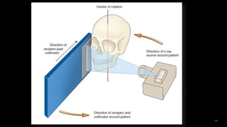


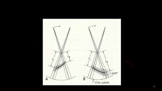


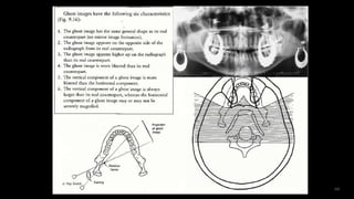


Panoramic radiography provides a wide view of the dental arches and associated structures using a rotating x-ray beam. It was developed starting in the 1920s to image the entire jaw at once. Modern panoramic machines use tomography to produce a single focused plane, known as the focal trough. This allows for detailed imaging of teeth and jaw structures while minimizing radiation exposure compared to full mouth x-rays. Panoramic images can reveal both normal anatomy as well as abnormalities, though some structures may appear as doubled "ghost images" due to the scanning technique.


