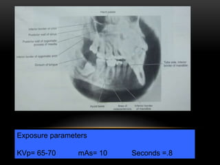
Thorough knowledge of the indications of various extra oral techniques allows accurate and timely diagnosis of various maxillofacial pathologies. Further, we can arrive at a diagnosis with minimum number of x-rays there by reducing patient exposure to radiation.
brief description about CONTENTS Introduction Principles of panoramic imaging Image layer Panoramic machines Panoramic film Patient positioning Interpreting the panoramic imaging INDICATION Advantages Disadvantages Conclusion References
3. INTRODUCTION • Panoramic imaging also called pantomography is a technique for producing a single tomographic image of facial structures that includes both the maxillary and mandibular dental arches and their supporting structures . • This is a curvilinear variant of conventional tomography.
4. PRINCIPLES OF PANORAMIC IMAGE FORMATION • Patero and Numata - describe the principles of panoramic radiography • based on the principle of reciprocal movement of x-ray source and an image receptor around a central point or plane called the image layer, in which the OBJECT of image is located. • OBJECT in front or behind this image are not clearly captured because of their movement relative to the centre of rotation of the receptor and the x-ray source.
5. The film and x-ray tubehead move around the patient in opposite directions in panoramic radiography
6. ROTATION CENTER The pivotal point or axis around which the cassette carrier and tube head rotate is termed rotation center Three basic rotation center used in panoramic radiography Double centre rotation Triple centre rotation moving centre rotation The location and number of rotational centers INFLUENCE size and shape of focal trough
7. IMAGE LAYER • Also known as focal trough • It is a three dimensional curved zone where the structures lying within this layer are reasonably well defined on final panoramic image. • The structures seen on a panoramic image are primarily those located within image layer. • OBJECTSoutside the image layer are blurred magnified are reduced in size. Even distorted to the extent of not being recognizable. • This shape of image layer varies with the brand of equipment used.
8. FOCAL TROUGH
9. FACTORS AFFECTING SIZE OF IMAGE LAYER: Arc path Velocity of receptor and X-ray tube head Alignment of x-ray beam Collimator width The location of image layer change with extensive machine used so recalibration may be necessary if consistently suboptimal images are produced. As a position of object is moved within the image layer size and shape of image layer change.
10. PANORAMIC UNIT
11. A, Orthophos XG Plus extraoral x-ray machine. B, Orthoralix 8500 extraoral x-ray machine. C, Example of a digital panoramic system
12. PARTS OF PANORAMIC UNITS a. x-ray tube head b. head positioner: chin rest notched bite block forehead rest lateral head support c. exposure controls
13. X-RAY TUBE HEAD: • Similar to intraoral x-ray tube head • Each has a filament to produce electrons and a target to produce x-rays • Collimator is a lead plate with narrow vertical slit • Narrow x-ray beam emerges from collimator minimize patient exposure to radiation
1
This presentation will give you a detailed knowledge about the various techniques that can be performed for imaging various aspects and diseases of TM Joint.
this contains the occlusal radiography methods for both maxillary and mandibular different occusal radiographic techniques, principles, classification, indications
Bisecting angle vs paralleling technique /orthodontic courses by Indian denta...Indian dental academy
The Indian Dental Academy is the Leader in continuing dental education , training dentists in all aspects of dentistry and
offering a wide range of dental certified courses in different formats.for more details please visit
www.indiandentalacademy.com
Temporomandibular joint imaging 2 /certified fixed orthodontic courses by Ind...Indian dental academy
The Indian Dental Academy is the Leader in continuing dental education , training dentists in all aspects of dentistry and offering a wide range of dental certified courses in different formats.
Indian dental academy provides dental crown & Bridge,rotary endodontics,fixed orthodontics,
Dental implants courses.for details pls visit www.indiandentalacademy.com ,or call
0091-9248678078
Extra oral radiography means that the source as well as film are placed outside the mouth & an exposure is made in order to obtain the images on a recording medium. Extra oral radiography provides wider anatomic coverage on a single film.
This presentation covers routinely used intraoral & extraoral plain radiographs used in assessment of maxillofacial trauma patients with extended coverage on occlusal radiographs. This PPT is echanced with addition of images for all radiographs
The Indian Dental Academy is the Leader in continuing dental education , training dentists in all aspects of dentistry and
offering a wide range of dental certified courses in different formats.for more details please visit
www.indiandentalacademy.com
Explore natural remedies for syphilis treatment in Singapore. Discover alternative therapies, herbal remedies, and lifestyle changes that may complement conventional treatments. Learn about holistic approaches to managing syphilis symptoms and supporting overall health.
- Video recording of this lecture in English language: https://youtu.be/lK81BzxMqdo
- Video recording of this lecture in Arabic language: https://youtu.be/Ve4P0COk9OI
- Link to download the book free: https://nephrotube.blogspot.com/p/nephrotube-nephrology-books.html
- Link to NephroTube website: www.NephroTube.com
- Link to NephroTube social media accounts: https://nephrotube.blogspot.com/p/join-nephrotube-on-social-media.html
ARTIFICIAL INTELLIGENCE IN HEALTHCARE.pdfAnujkumaranit
Artificial intelligence (AI) refers to the simulation of human intelligence processes by machines, especially computer systems. It encompasses tasks such as learning, reasoning, problem-solving, perception, and language understanding. AI technologies are revolutionizing various fields, from healthcare to finance, by enabling machines to perform tasks that typically require human intelligence.
Flu Vaccine Alert in Bangalore Karnatakaaddon Scans
As flu season approaches, health officials in Bangalore, Karnataka, are urging residents to get their flu vaccinations. The seasonal flu, while common, can lead to severe health complications, particularly for vulnerable populations such as young children, the elderly, and those with underlying health conditions.
Dr. Vidisha Kumari, a leading epidemiologist in Bangalore, emphasizes the importance of getting vaccinated. "The flu vaccine is our best defense against the influenza virus. It not only protects individuals but also helps prevent the spread of the virus in our communities," he says.
This year, the flu season is expected to coincide with a potential increase in other respiratory illnesses. The Karnataka Health Department has launched an awareness campaign highlighting the significance of flu vaccinations. They have set up multiple vaccination centers across Bangalore, making it convenient for residents to receive their shots.
To encourage widespread vaccination, the government is also collaborating with local schools, workplaces, and community centers to facilitate vaccination drives. Special attention is being given to ensuring that the vaccine is accessible to all, including marginalized communities who may have limited access to healthcare.
Residents are reminded that the flu vaccine is safe and effective. Common side effects are mild and may include soreness at the injection site, mild fever, or muscle aches. These side effects are generally short-lived and far less severe than the flu itself.
Healthcare providers are also stressing the importance of continuing COVID-19 precautions. Wearing masks, practicing good hand hygiene, and maintaining social distancing are still crucial, especially in crowded places.
Protect yourself and your loved ones by getting vaccinated. Together, we can help keep Bangalore healthy and safe this flu season. For more information on vaccination centers and schedules, residents can visit the Karnataka Health Department’s official website or follow their social media pages.
Stay informed, stay safe, and get your flu shot today!
NVBDCP.pptx Nation vector borne disease control programSapna Thakur
NVBDCP was launched in 2003-2004 . Vector-Borne Disease: Disease that results from an infection transmitted to humans and other animals by blood-feeding arthropods, such as mosquitoes, ticks, and fleas. Examples of vector-borne diseases include Dengue fever, West Nile Virus, Lyme disease, and malaria.
New Drug Discovery and Development .....NEHA GUPTA
The "New Drug Discovery and Development" process involves the identification, design, testing, and manufacturing of novel pharmaceutical compounds with the aim of introducing new and improved treatments for various medical conditions. This comprehensive endeavor encompasses various stages, including target identification, preclinical studies, clinical trials, regulatory approval, and post-market surveillance. It involves multidisciplinary collaboration among scientists, researchers, clinicians, regulatory experts, and pharmaceutical companies to bring innovative therapies to market and address unmet medical needs.
Title: Sense of Smell
Presenter: Dr. Faiza, Assistant Professor of Physiology
Qualifications:
MBBS (Best Graduate, AIMC Lahore)
FCPS Physiology
ICMT, CHPE, DHPE (STMU)
MPH (GC University, Faisalabad)
MBA (Virtual University of Pakistan)
Learning Objectives:
Describe the primary categories of smells and the concept of odor blindness.
Explain the structure and location of the olfactory membrane and mucosa, including the types and roles of cells involved in olfaction.
Describe the pathway and mechanisms of olfactory signal transmission from the olfactory receptors to the brain.
Illustrate the biochemical cascade triggered by odorant binding to olfactory receptors, including the role of G-proteins and second messengers in generating an action potential.
Identify different types of olfactory disorders such as anosmia, hyposmia, hyperosmia, and dysosmia, including their potential causes.
Key Topics:
Olfactory Genes:
3% of the human genome accounts for olfactory genes.
400 genes for odorant receptors.
Olfactory Membrane:
Located in the superior part of the nasal cavity.
Medially: Folds downward along the superior septum.
Laterally: Folds over the superior turbinate and upper surface of the middle turbinate.
Total surface area: 5-10 square centimeters.
Olfactory Mucosa:
Olfactory Cells: Bipolar nerve cells derived from the CNS (100 million), with 4-25 olfactory cilia per cell.
Sustentacular Cells: Produce mucus and maintain ionic and molecular environment.
Basal Cells: Replace worn-out olfactory cells with an average lifespan of 1-2 months.
Bowman’s Gland: Secretes mucus.
Stimulation of Olfactory Cells:
Odorant dissolves in mucus and attaches to receptors on olfactory cilia.
Involves a cascade effect through G-proteins and second messengers, leading to depolarization and action potential generation in the olfactory nerve.
Quality of a Good Odorant:
Small (3-20 Carbon atoms), volatile, water-soluble, and lipid-soluble.
Facilitated by odorant-binding proteins in mucus.
Membrane Potential and Action Potential:
Resting membrane potential: -55mV.
Action potential frequency in the olfactory nerve increases with odorant strength.
Adaptation Towards the Sense of Smell:
Rapid adaptation within the first second, with further slow adaptation.
Psychological adaptation greater than receptor adaptation, involving feedback inhibition from the central nervous system.
Primary Sensations of Smell:
Camphoraceous, Musky, Floral, Pepperminty, Ethereal, Pungent, Putrid.
Odor Detection Threshold:
Examples: Hydrogen sulfide (0.0005 ppm), Methyl-mercaptan (0.002 ppm).
Some toxic substances are odorless at lethal concentrations.
Characteristics of Smell:
Odor blindness for single substances due to lack of appropriate receptor protein.
Behavioral and emotional influences of smell.
Transmission of Olfactory Signals:
From olfactory cells to glomeruli in the olfactory bulb, involving lateral inhibition.
Primitive, less old, and new olfactory systems with different path
Acute scrotum is a general term referring to an emergency condition affecting the contents or the wall of the scrotum.
There are a number of conditions that present acutely, predominantly with pain and/or swelling
A careful and detailed history and examination, and in some cases, investigations allow differentiation between these diagnoses. A prompt diagnosis is essential as the patient may require urgent surgical intervention
Testicular torsion refers to twisting of the spermatic cord, causing ischaemia of the testicle.
Testicular torsion results from inadequate fixation of the testis to the tunica vaginalis producing ischemia from reduced arterial inflow and venous outflow obstruction.
The prevalence of testicular torsion in adult patients hospitalized with acute scrotal pain is approximately 25 to 50 percent
These lecture slides, by Dr Sidra Arshad, offer a quick overview of physiological basis of a normal electrocardiogram.
Learning objectives:
1. Define an electrocardiogram (ECG) and electrocardiography
2. Describe how dipoles generated by the heart produce the waveforms of the ECG
3. Describe the components of a normal electrocardiogram of a typical bipolar leads (limb II)
4. Differentiate between intervals and segments
5. Enlist some common indications for obtaining an ECG
Study Resources:
1. Chapter 11, Guyton and Hall Textbook of Medical Physiology, 14th edition
2. Chapter 9, Human Physiology - From Cells to Systems, Lauralee Sherwood, 9th edition
3. Chapter 29, Ganong’s Review of Medical Physiology, 26th edition
4. Electrocardiogram, StatPearls - https://www.ncbi.nlm.nih.gov/books/NBK549803/
5. ECG in Medical Practice by ABM Abdullah, 4th edition
6. ECG Basics, http://www.nataliescasebook.com/tag/e-c-g-basics
6. Father of Panoramic Radiography
•1949, extra-oral films
•X-ray source - stationary
Dr Yrjo Veli Paatero
7. What is panoramic imaging
/pantomography???
A technique for producing a single tomographic
image of the facial structures that includes both
the maxillary and mandibular dental arches and
their supporting structures.
8. ‘Panorama’ ‘Tomography’
An
unobstructed
view of a
region in
every
direction
An X-ray technique
for making
radiographs of
layers of tissue in
depth without the
interference of
tissues above and
below the level
PANTOMOGRAPHY
15. BONY LANDMARKS IN MAXILLA
15
15
15. Glenoid fossa
19. Floor of Max.Sinus
17. Zygomatic Arch16. Articular eminence 18.Post. wall max. sinus
20. Zygomatic process of max. forming innominate line
21. Hard palate 22. Floor of the orbit 23. Nasal septum 24. Incisive foramen
25. Inferior choncha 26. Meatus 27. Frontal process of Z.bone
16
17
18
19
20
21
22
23
29
25
24
26
28.Pterygo max. fissure
30. Maxillary tuberosity29.Spine of the sphenoid bone 31. Lateral pterygoid plate
31
30
28
27
16. OTHER STRUCTURES
16
32
32. External acoustic meatus 34. Shadow of ear lobe33. Styloid process
35. nose 36. Shadow of Cervical spine
33
34
35
36 37
37. Cervical vertebrae
38
38. Nasopharyngeal space 39. Shadow of uvula
40
39
40 Submandibular fossa
17. A panoramic film is not
as useful as periapical
radiography for
detecting small carious
lesions, periodontal
diseases, or periapical
lesions.
It should not be used as a
substitute for intraoral
films.
30. During the exposure cycle, the machine shiftsto one or
more additional rotation centers.
This rotational change allowsthe image layer to
conformto the shape of the dental arches.
The location and no. of rotational centers influence the
size and shape of the focal trough.
31. Focal
trough
The focal trough (also
known as the Image layer)
is defined as a 3-D
curved zone in which
structures are clearly
demonstrated on a
panoramic radiograph.
32. Advantages
1. Fieldsize
2. Minimal exposure
3. Simplicity
4. Patient cooperation
5. Useful in patients with trismus & gagging
6. Valuable visual aid for patient education
33. Disadvantages
1. Cannot be usedin detection of caries and periodontal disease.
2. Overlapping of teethin premolar region
3. Focal trough limitations
4. Shadowof cervical spine in the lower anterior region.
5. Ghost images
6. Equipment cost
47. LATERAL CEPHALOMETRIC
PROJECTION
Film position - cassette is
placed perpendicular to the floor
with long axis of the cassette
placed vertically.
Position of patient - left side
of the face is positioned against
the cassette. Mid sagittal plane is
perpendicular to the floor and
parallel to film.
Central ray - perpendicular to
the film.
49. INDICATIONS
• To evaluate facial growth and
development, trauma, disease and
developmental anomalies.
• Demonstrates the bones of the face,
skull as well as the soft tissue profile
of the face.
50. Film position - cassette is
perpendicular to the floor with long
axis of the cassette placed vertically.
Position of patient –The film is
adjusted so that the upper
circumference of the skull is .5 inch
below the lower border of the cassette.
Central ray - perpendicular to the film
towards the E.A.M.
TRUE LATERAL SKULL
52. To survey skull and facial bone for trauma or pathology.
Nasopharangeal soft tissue, paranasal sinus and hard
palate.
Condition affecting sella turcica, such as tumour of pitutary
gland in acromegaly.
Indications
53. 7/29/2014 53
PA WATERS PROJECTION
Film position - cassette is
perpendicular to the floor with
long axis of the cassette placed
vertically.
Position of patient - mid
sagittal plane perpendicular to the
floor and parallel to film.
Head is extended so that only the
chin touches the casette.
The tip of nose is .5 to 1.5 cm
away from the cassette
Central ray- perpendicular
and to the midpoint of the film.
55. INDICATIONS
55
• Demonstrate the maxillary , frontal and ethmoidal
sinuses.
• The orbit, frontozygomatic suture, nasal cavity,
coronoid process of the mandible and the zygomatic
arch are also seen.
56. 56
Film position- cassette is placed
perpendicular to the floor with long
axis of the cassette placed
horizontally.
Position of patient- head is
centered on the cassette (Head and
neck tipped back).Vertex of the skull
touches the cassette.
Central raY- perpendicular to the
film. It enters via between angle of
mandible and in a coronal plane ¾
inches anterior to the external
auditory meatus.
SUBMENTOVERTEX (BASE)
PROJECTION
58. INDICATIONS
58
Help to study destructive lesion affecting
the palate, pterygoid region or base of the
skull, sphenoidal sinus.
Fractures of zygomatic arches (JUG
HANDLE).
59. LATERAL OBLIQUE
Film position - flat against the
patient cheeks and is centered over
the body of the mandible.
Position of patient - ala tragus line
is parallel to the floor. Inferior border
of the cassette should be parallel to
the lower border of the mandible and
below it.
Central ray - directed 2cm behind
the angle of the mandible and beam
is directed -10° to -15°
61. Lateral Oblique Views - Largely
replaced by panoramic views
Indications:
• Impacted third molars
• fractures of the ramus, condyle or body of
the mandible.
61
63. TRANSCRANIAL VIEW
63
Film position - cassette is
placed flat against the patient ear
and centred over the TMJ of
interest.
Position of patient - head is
adjusted so that the saggital plane
is vertical.
The ala tragus is parallel to floor.
Central ray - is ½ inch behind
and 2 inch above the auditory
meatus
64. 64
Exposure parameters
KVp= 70
mAs= .7
Seconds =1.5
Indications
• Arthritic changes on the articular surface.
• To evaluate the joint’s bony relationship.
65. TRANSPHARYNGEAL VIEW
65
Film position - cassette is placed
flat against the patient ear and is
centered to a point ½’” anterior to
ext. auditory meatus, over the TMJ
of interest.
Position of patient - head is
adjusted so that the saggital plane is
vertical.The ala tragus is parallel to
floor.
Central ray - from the opposite
side cranially at an angle -5° to -10°.
66. INDICATIONS
66
• Fracture of condylar head and neck of the mandible
Exposure
parameters
KVp= 70
mAs= 7
Seconds =1.5
67. VIEW
67
Film position - cassette is placed
behind the patient’s head at an angle
of 45° to the saggital plane.
Position of patient - head is
adjusted so that the saggital plane is
vertical. The canthomeatal line is
parallel to floor. The mouth should be
wide open.
Central ray - from the opposite side
cranially at an angle -5° to -10°.
68. INDICATIONS
68
The anterior view of the temporomandibular joint
Medial displacement of fractured condyle
Fracture of neck of condyle.
There is minimum superimposition.
Exposure
parameters
KVp= 70
mAs= 7
Seconds =.8
69. REVERSE-TOWNE PROJECTION(OPEN
MOUTH)
69
Film position - cassette is
placed perpendicular to the floor
with long axis of the cassette
placed horizontally.
Position of patient-
Pt. forehead and tip of the nose
should touch the film and is
asked to keep his mouth wide
open
Central ray- directed via mid
saggital plane at the level of the
mandible and is perpendicular
to the film.
70. 70
Exposure
parameters
KVp = 65
mAs = 10
Seconds = 2-3
INDICATIONS:
• Suspected fracture of the condylar neck.
• Intracapsular fracture of the TMJ
• Shows posterolateral wall of maxillary sinus
71. DRAWBACKS OF EXTRA ORAL
TECHNIQUES
71
Magnification occurs due to the greater object
to film distance used.
Details are not well defined.
Contrast is reduced as the secondary
radiation produced by the soft tissues is
more.
It is a 2- D image of 3- D structure.
72. CONCLUSION
Thorough knowledge of the indications of
various extra oral techniques allows accurate
and timely diagnosis of various maxillofacial
pathologies. Further, we can arrive at a
diagnosis with minimum number of x-rays
there by reducing patient exposure to
radiation.
73. • White SC, Pharoah MJ.Oral Radiology
Principles And Interpretations.6thelsevier::
Missouri; 2009
• Mac Donald,Avery.Dentistry For The Child
And Adolscent.9th.elsevier: Missouri; 2011
• Langland and Langlais.. Principles Of Dental
Imaging.7thed.elsevier: Muir; 2005
• Freny R,Karjodkar.Textbook Of Dental And
Maxillofacial Radiology.6thed.elsevier: Reed;
2000
• Dental radiography, Principles and
Techniques; Haring, Howerton;Third
edition.
Dr patero was the first to describe principal of panoramic radiography and extra oral film.
He kept the xray source stationary while the pt and film was moving constantly
Moving on to the --
Tpantomography is derived 4m 2 words – panorama and tomography
The main component are
Next is the working of panoramic radiography
As the tubehead rotates around the patient, the x-ray beam passes through different parts of the jaws, producing multiple images that appear as one continuous image on the film (“panoramic view”).
When you click the mouse, the tubehead will rotate around the patient and produce the images. The red dots represent the sliding rotation center.
Click the mouse to align and merge these individual images into one continuous image.
Implants can be well appreciated in opg
In panoramic radiography, the film/ cassette carrier and X-ray tubehead are connected and rotate simultaneously around a patient during exposure.
Depending on the manufacturer, the no. and location of the rotational center differ.
One of the three basic rotation centers is used in panoramic X-ray machines as follows:
DOUBLE- CENTER ROTATION
TRIPLE- CENTER ROTATION
MOVING- CENTER ROTATION
Triple centre of rotation machines have 3 rotation centre and create an uninterrupted radiographic image of the jaws
Machine rotates around a contnously moving center that is similar to the arches, and create an uninterrupted image of the jaws
FUNDAMENTALS OF PANORAMIC IMAGING
Previously xray source wase kept stationary while the Movement of film and object about 2 fixed centre of rotation
In panoramic radiography, the film and X-ray tube head move around the patient.
The X-ray tube head rotate’]s around the patient’s head in one direction, while the film rotates in the opposite direction.
2.Movement of film and xray about 1 fixed centre of rotation
3.Movement of xray source and film about a shifting centre of rotation
The structures located within the focal trough appear reasonably well defined on the resulting panoramic radiograph.
The structures positioned inside or outside of the focal trough appear blurred/ indistinct and are not readily visible on the panoramic film.
Broad coverage of the facial bone and teeth.
The radiation dose is relatively low.
It is a simple procedure
It is Convienient for the pt.
It is Useful in patients with trismus & gagging
It is Valuable visual aid for patient education
Cannot be used in detection of caries and periodontal disease.
Panoramic image shows Overlapping of teeth in premolar region.
Focal trough limitations i.e the str outside the image layer cannot be visualised.
Shadow of cervical spine in the lower anterior region.
Formation of Ghost image.
MOVING ON TO
If the tongue is not placed on the roof of the mouth, a radioluscent shadow will be superimposed over the apices of the max teeth
If the frankfort plane is rotated upward,it results in overlapping of the images of the teeth and an opaque shadow obcuring the root of the max teeth
an exaggerated smile seen on the panoramic film If the frankfort plane is rotated downward
if the teeth are positioned too far forward on the bite block ,the anterior teet appears skiny and out of focus i.e., blured and narrow
if the teeth are positioned too far back on the bite block ,the anterior teeth appears fat and out of focus.
If the pt head is not centered , the ramus and post teeth appears unequally magnified
If the pt moves while taking an opg it results in distorted image
If the pt is not standing erect, supermposition of the cervical spine may be seen on the centre of the film
combination
Pt is asked to keep the teeth in occlusion
Film positioning is similar as that of the true lateral
All the 3 exposure parameter are less than that of lateral ceph
The main drawback wid this tech is the superimposition occurs
To reveal the
It has least kvp same as that of reverse towne
It has highest tube current among all the e.0 tech
The exposur time 4 the zygomatic arch is rduced to approx 1/3 the normal exPosure time 4 SMV.
LESS 50kvp
Pt must hold the cassette in position with the thumb placed under the edge of the cassttte and palm against the outer surface of the cassette
Help to evaluate
Same exposure parameter as that of T.CRANIAL
Same parameter of exposure as that of pa waters view