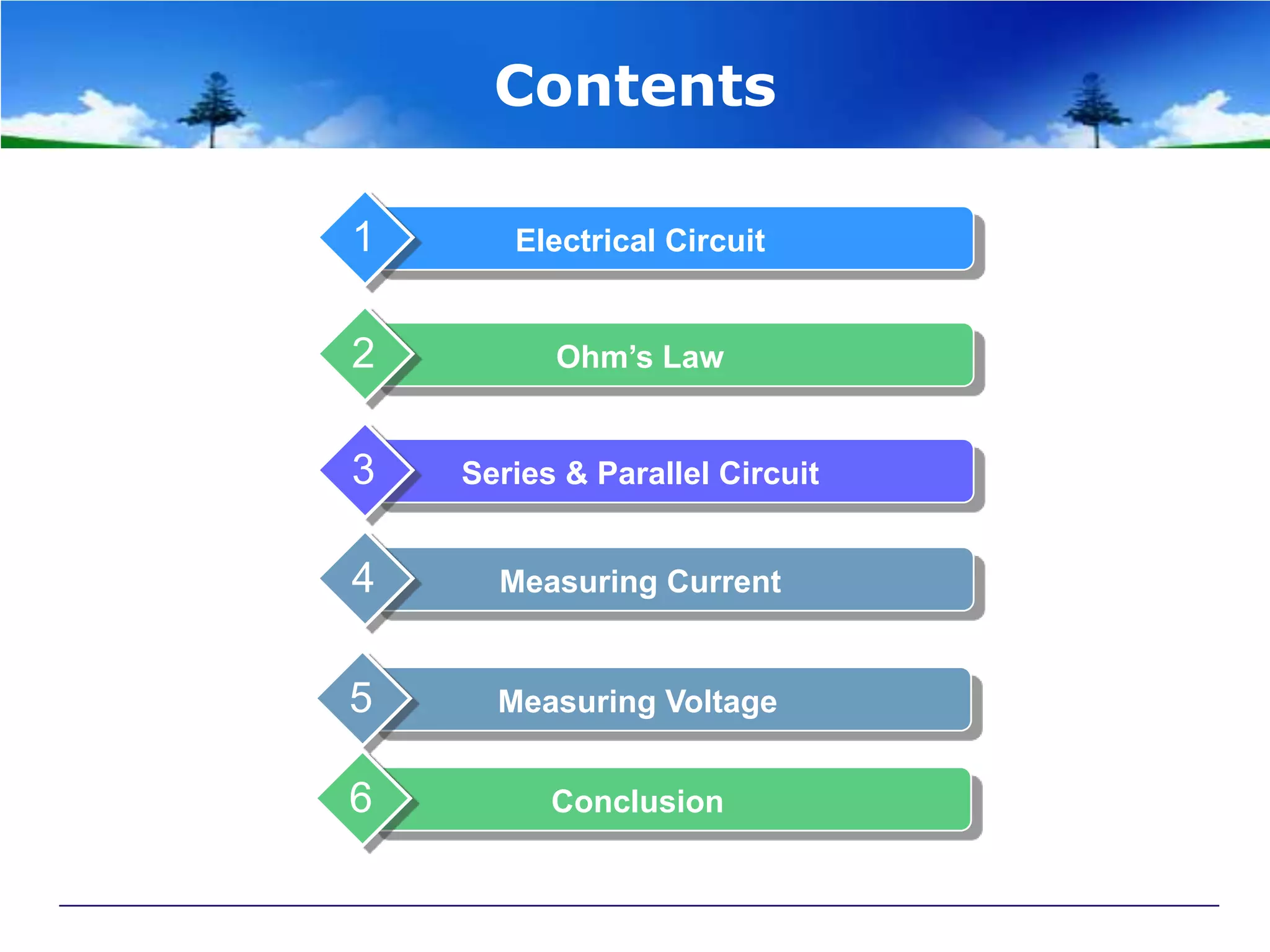
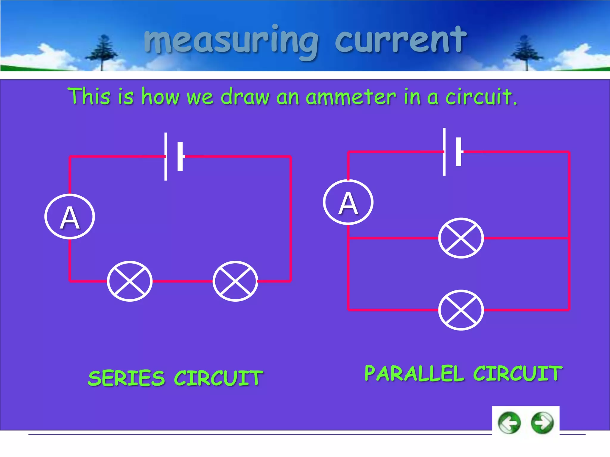
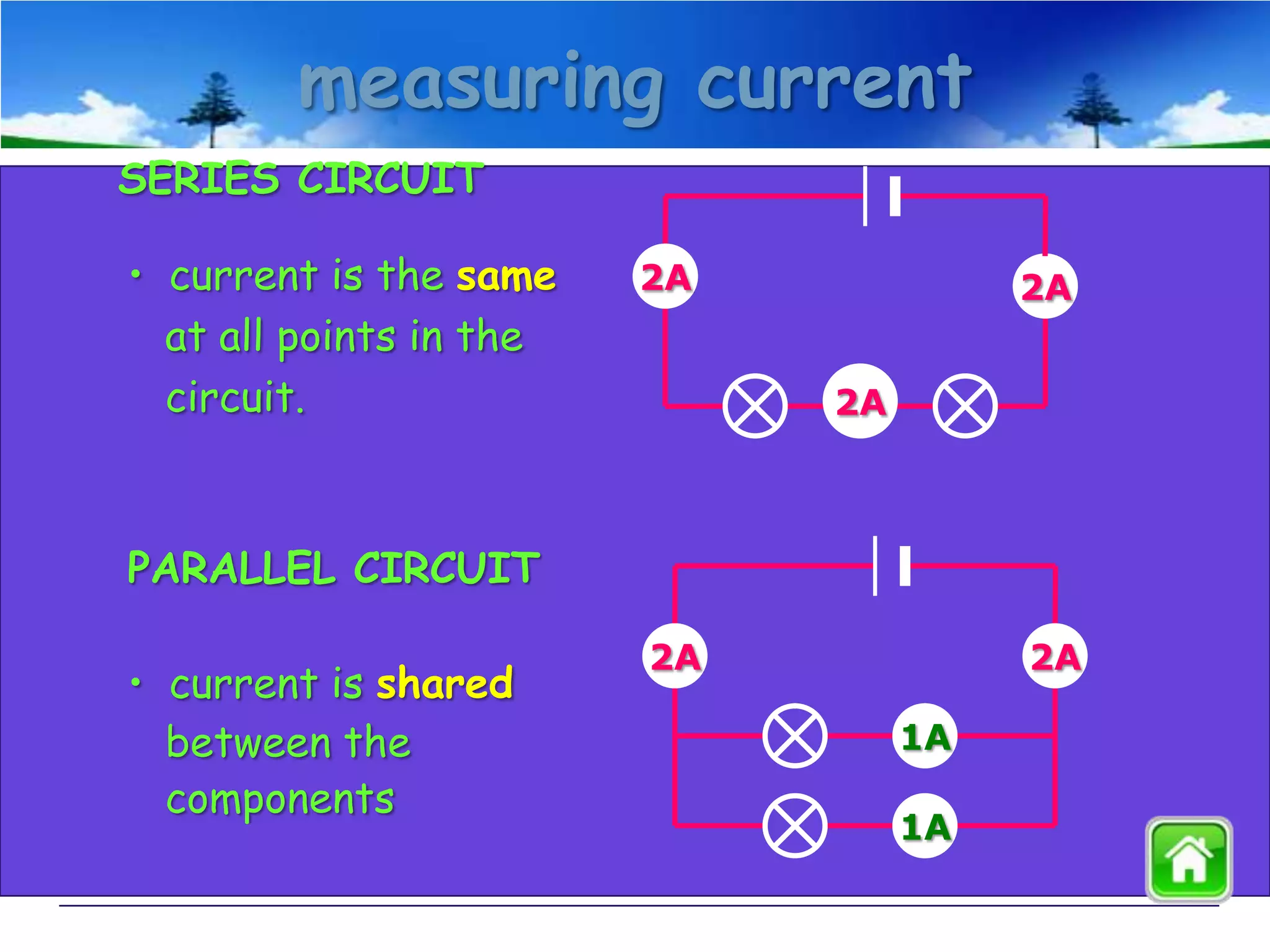
Principle of Electrical
Presenter:
Noraide Md Yusop
Rosazmir Mat Rashid
Mohd Norhisham Nordin
Azhar Md Saad
Chin Seng Fatt
Contents
1

Electrical Circuit

2

Ohm’s Law

3

Series & Parallel Circuit

4

Measuring Current

5

Measuring Voltage

6

Conclusion
ELECTRICAL CIRCUITS
All you need to be an inventor is a good
imagination and a pile of junk.
-Thomas Edison
Ohm’s Law

I=V/R
I
V

= Voltage (Volts)

R

Georg Simon Ohm (1787-1854)

= Current (Amperes) (amps)

= Resistance (ohms)
How you should be thinking
about electric circuits:

Voltage: a force that
pushes the current
through the circuit (in
this picture it would be
equivalent to gravity)
How you should be thinking
about electric circuits:

Resistance: friction that
impedes flow of current
through the circuit
(rocks in the river)
How you should be thinking
about electric circuits:

Current: the actual
“substance” that is
flowing through the
wires of the circuit
(electrons!)
Would This Work?
Would This Work?
Would This Work?
The Central Concept: Closed
Circuit
circuit diagram
Scientists usually draw electric circuits using symbols;

cell

lamp

switch

wires
Ohm’s Law Simulation

Click Here
Series and Parallel Circuits
Series Circuits
 only one end of each component is connected
 e.g. Christmas tree lights

Parallel Circuits
 both ends of a component are connected
 e.g. household lighting
series circuit
• voltage is shared between the components

3V

1.5V

1.5V
parallel circuit
• voltage is the same in all parts of the circuit.

3V
3V

3V
Simple Circuits
Series circuit
 All in a row
 1 path for electricity
 1 light goes out and
the circuit is broken

Parallel circuit
 Many paths for electricity
 1 light goes out and the
others stay on
measuring current
Electric current is measured in amps (A) using
an ammeter connected in series in the circuit.

A
measuring current
This is how we draw an ammeter in a circuit.

A

A

SERIES CIRCUIT

PARALLEL CIRCUIT
measuring current
SERIES CIRCUIT

• current is the same
at all points in the
circuit.

2A

2A
2A

PARALLEL CIRCUIT
• current is shared
between the
components

2A

2A
1A

1A
measuring voltage
The ‘electrical push’ which the cell gives to the current

is called the voltage. It is measured in volts (V) on a
voltmeter

V
measuring voltage
This is how we draw a voltmeter in a circuit.

V
SERIES CIRCUIT

V
PARALLEL CIRCUIT
measuring voltage
Different cells produce different voltages. The
bigger the voltage supplied by the cell, the bigger the
current.

Unlike an ammeter, a voltmeter is connected across
the components
Scientist usually use the term Potential Difference
(pd) when they talk about voltage.
Conclusion
Ohm law is V = I / R
Electric circuit has two types of
connection
 Series circuit
 Parallel circuit
• Voltage is measured using voltmeter by
connected across the components
• Current is measured using ammeter by
connected in series in the circuit.
The End

Principle of electricity