Downloaded 162 times
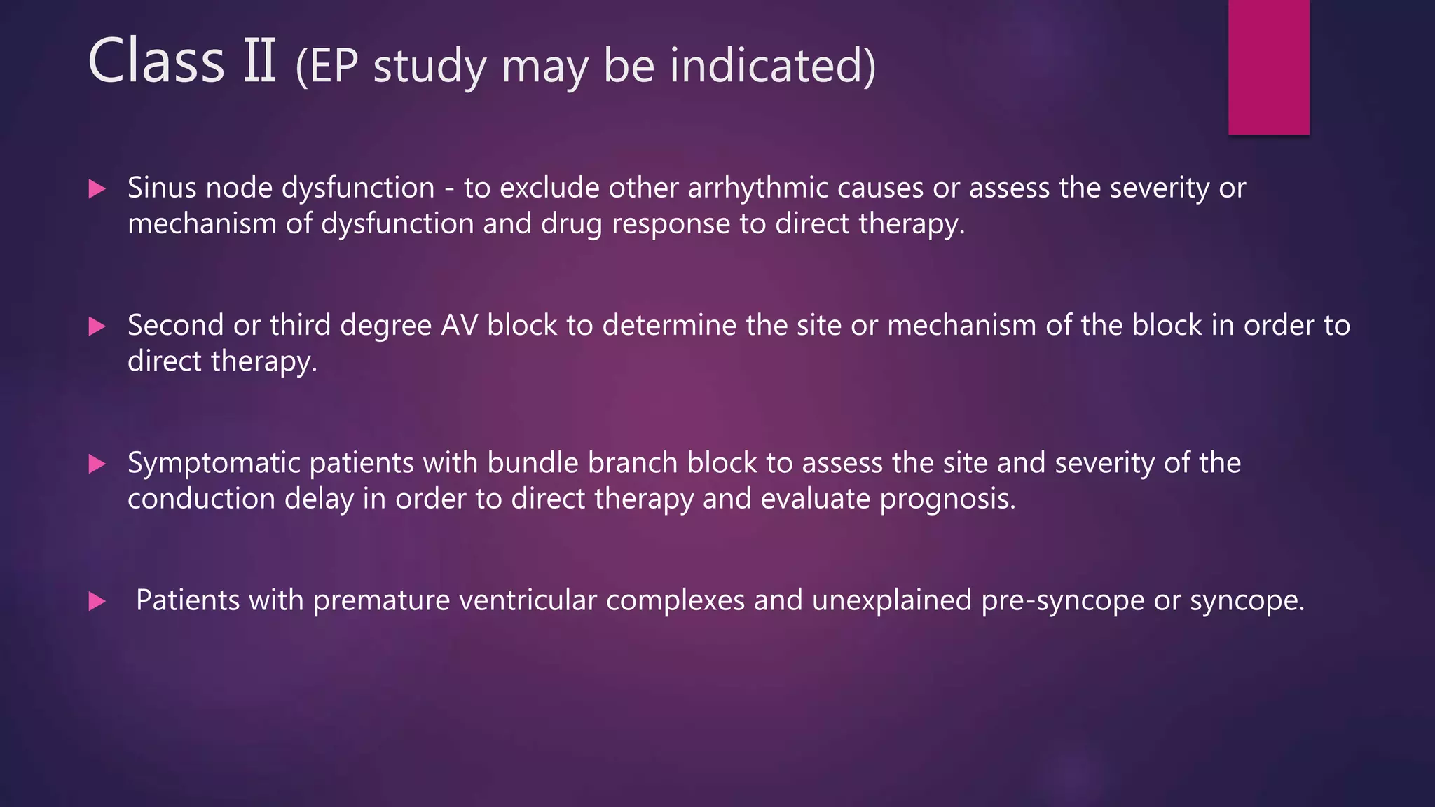
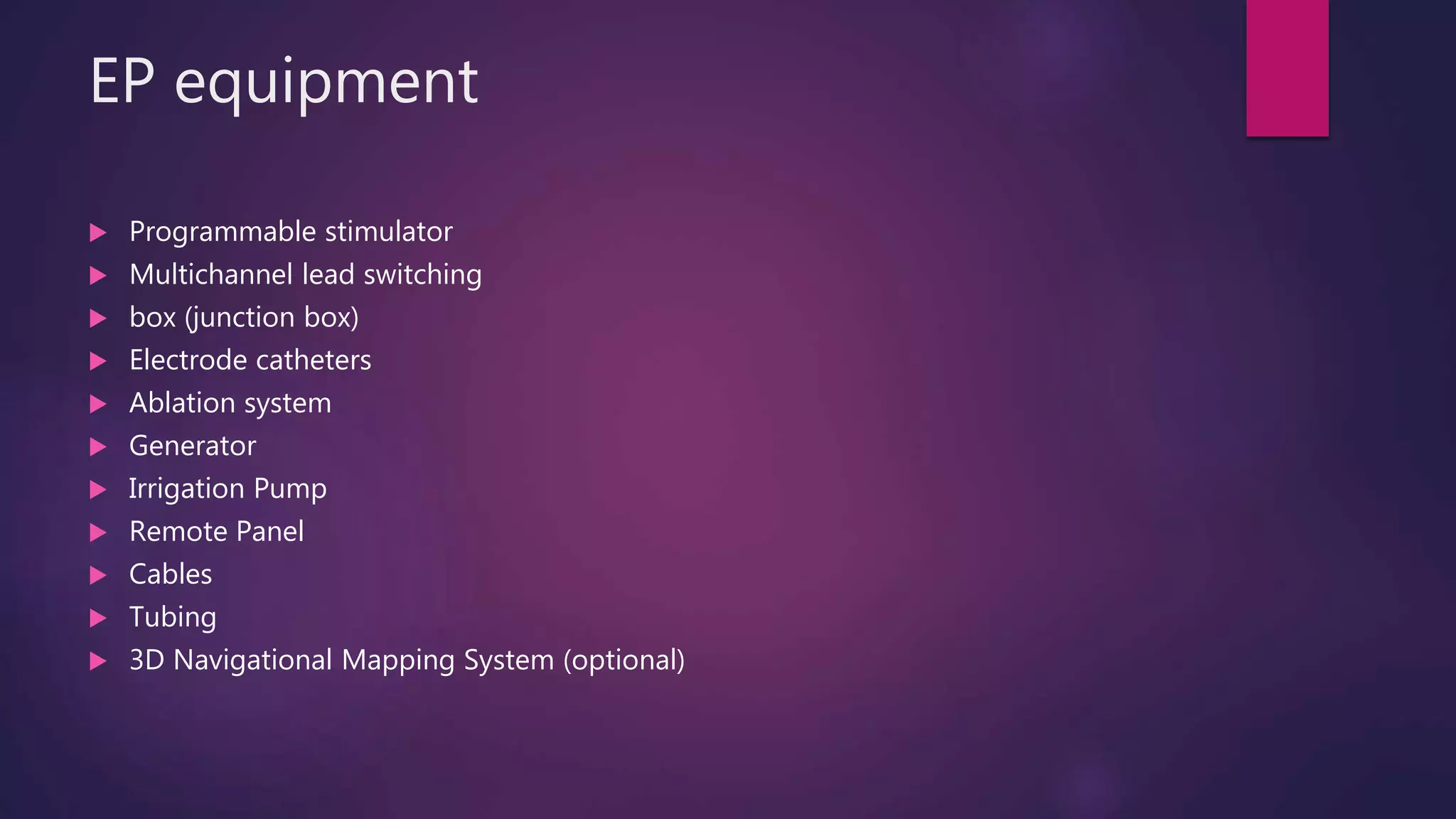
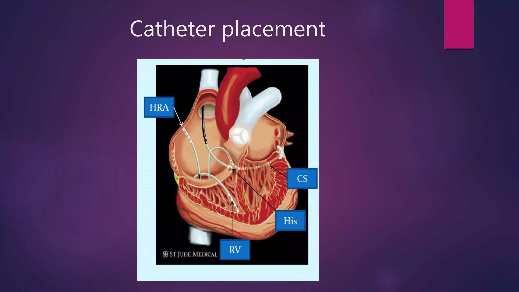
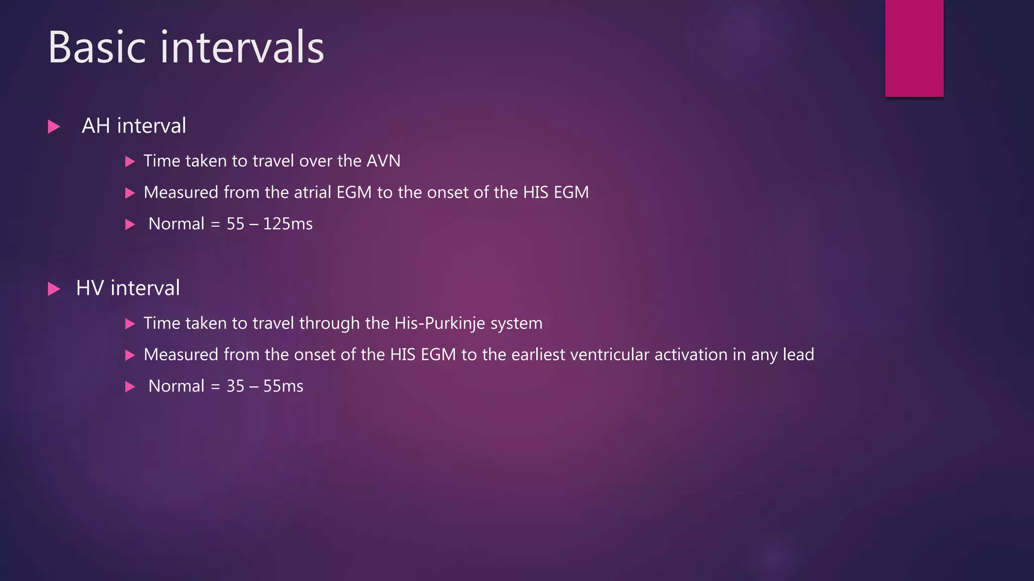
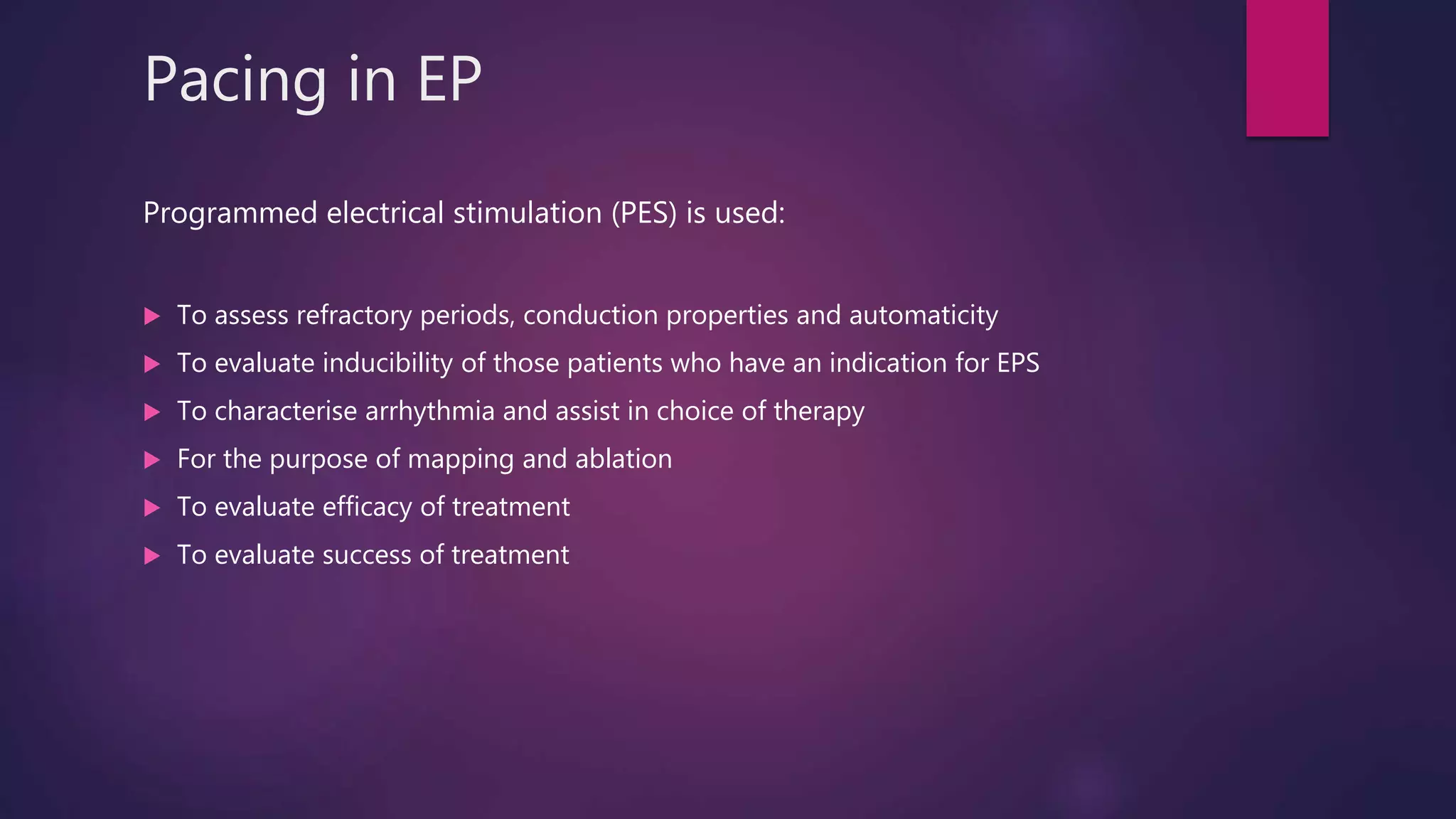
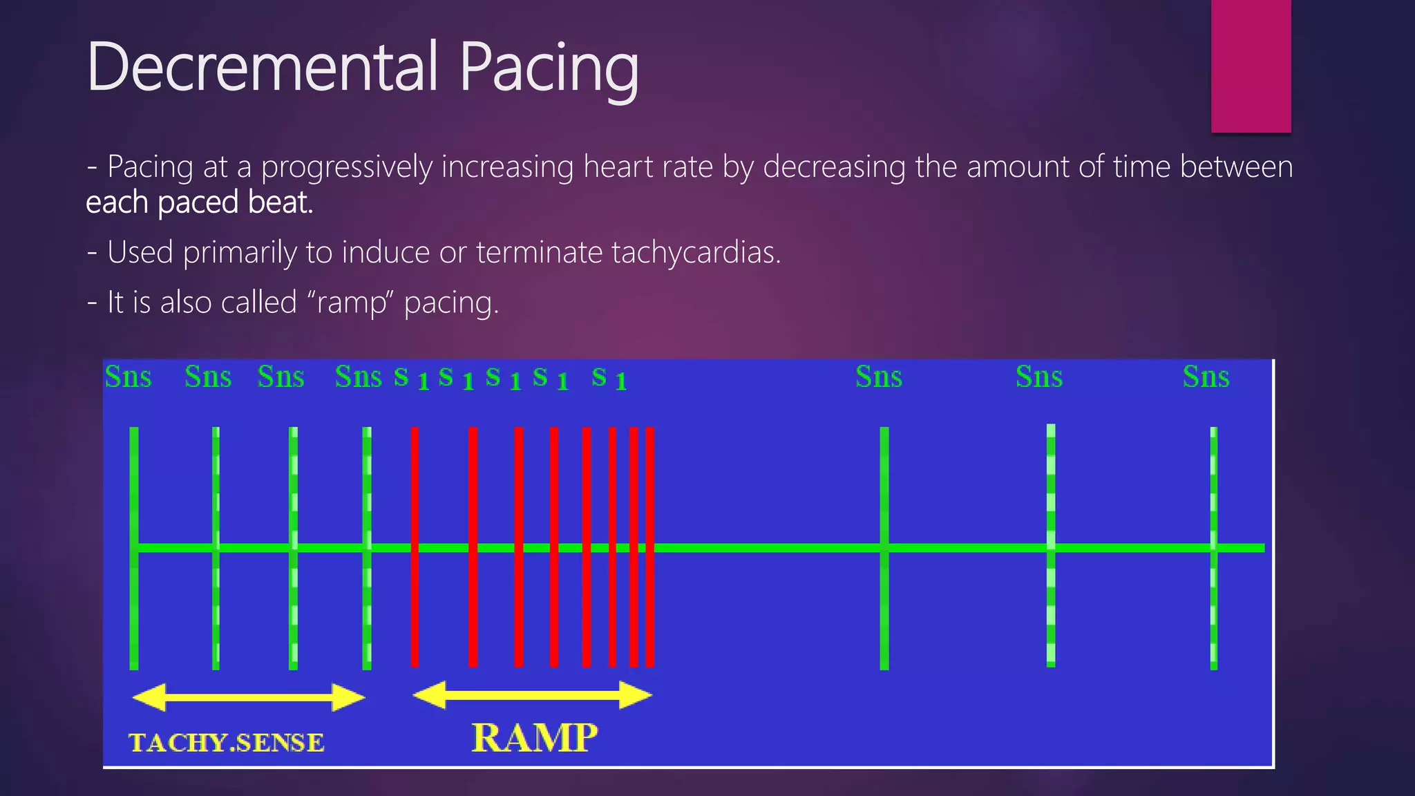
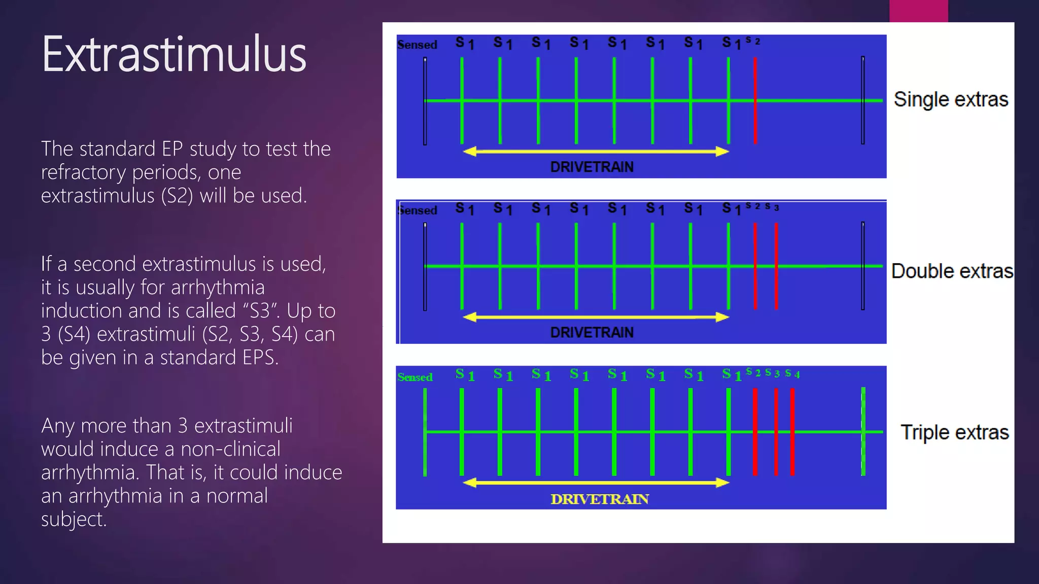

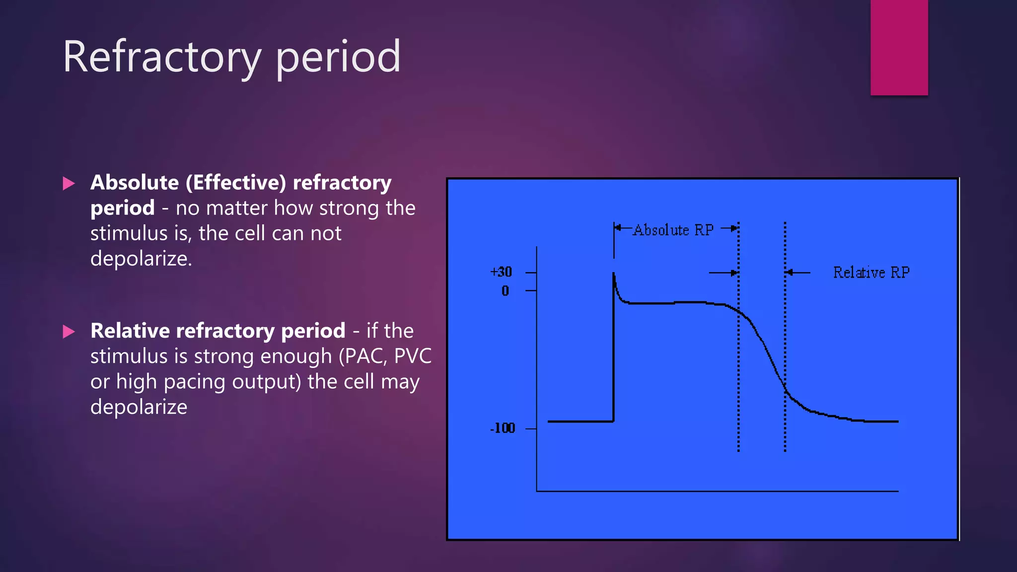
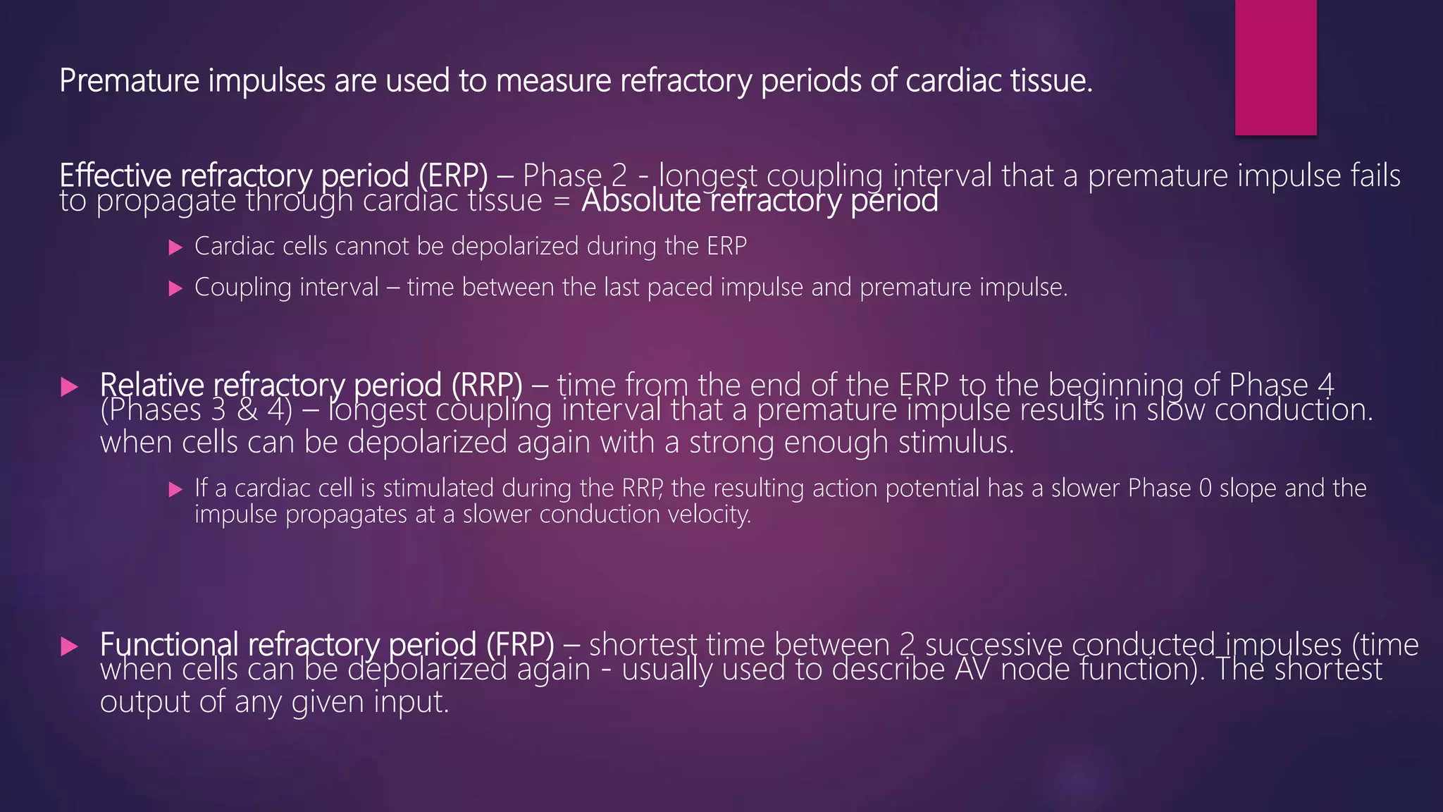
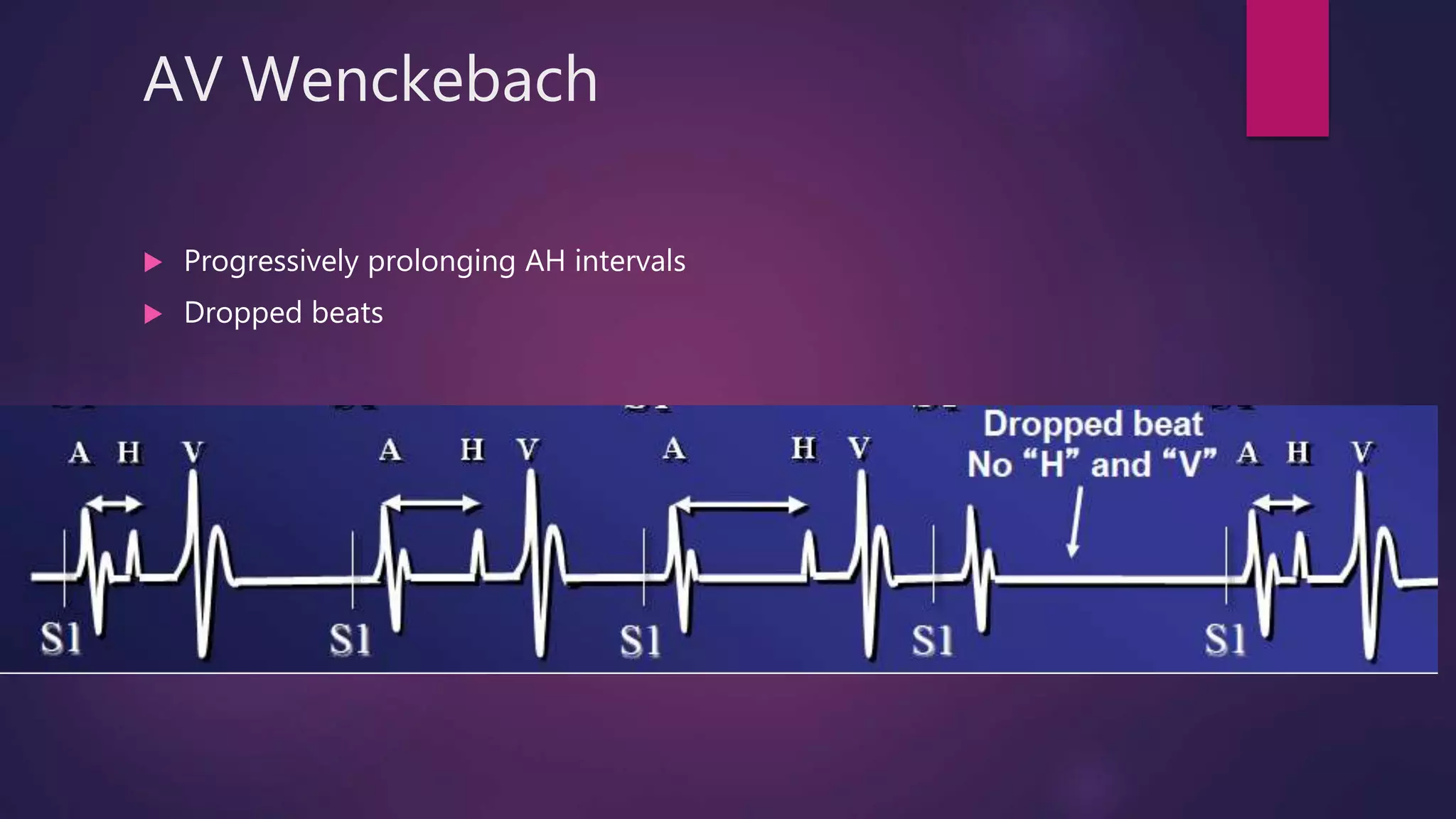
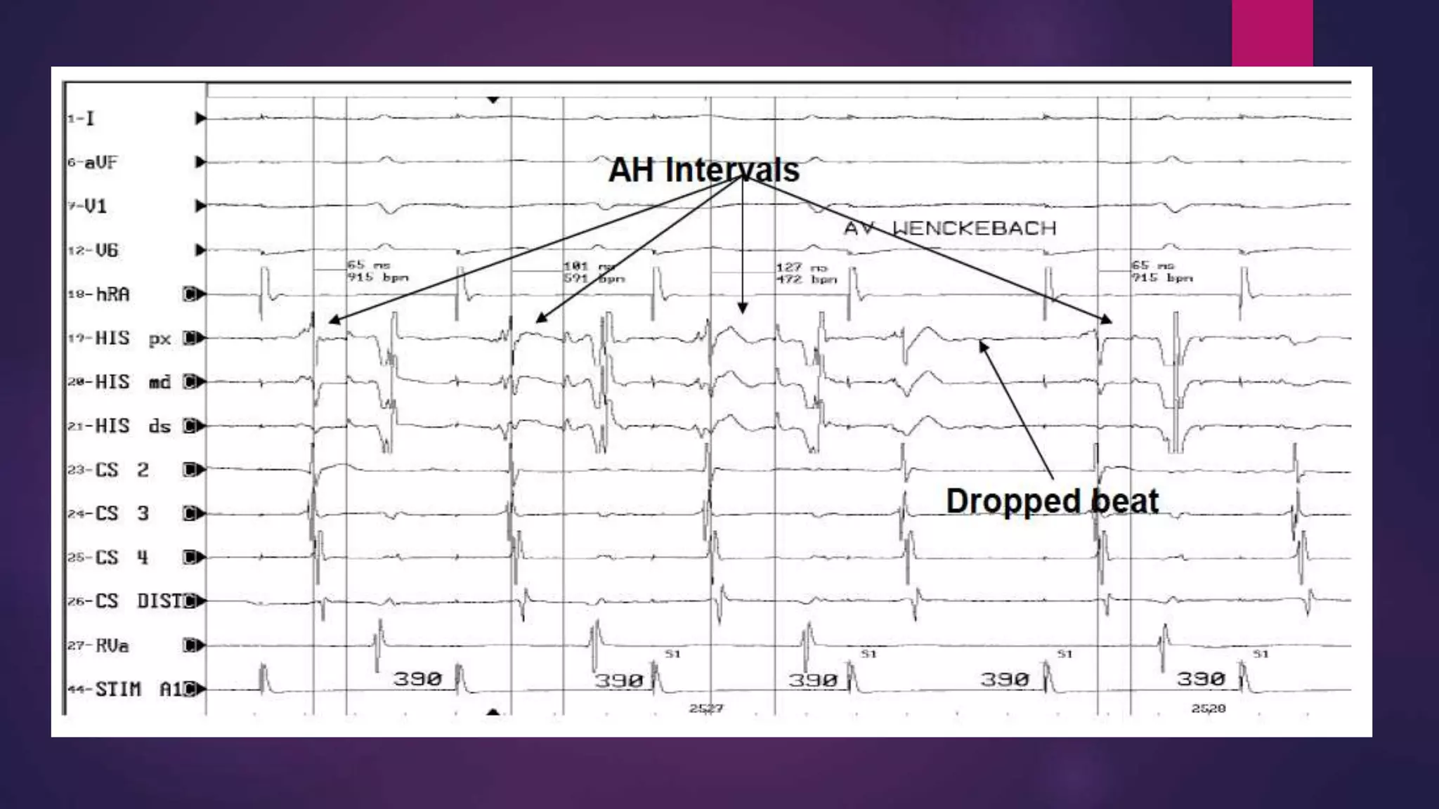
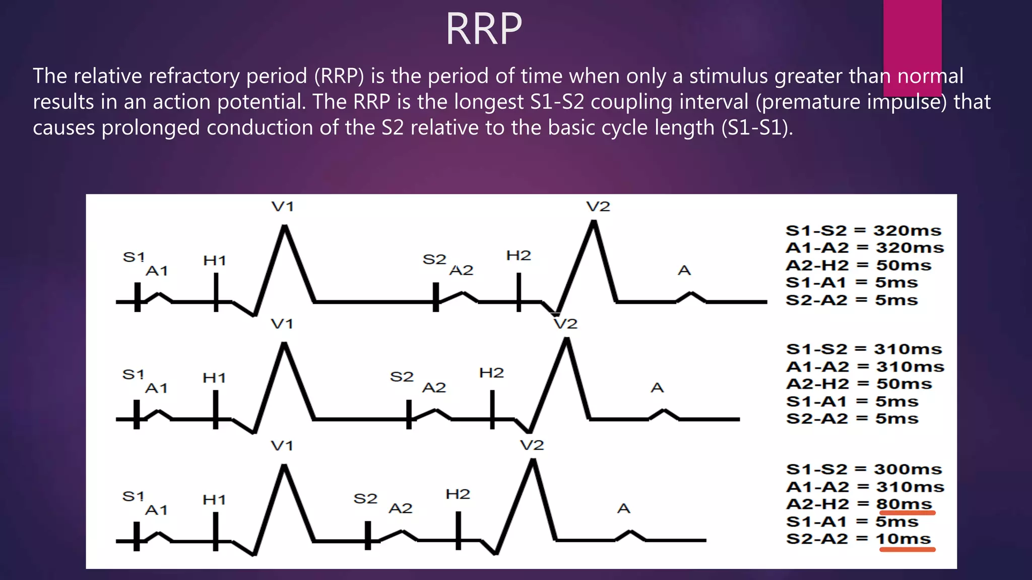

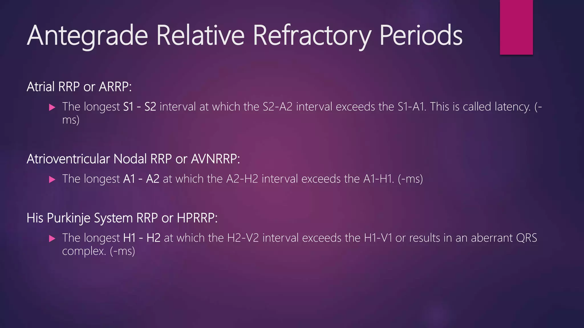
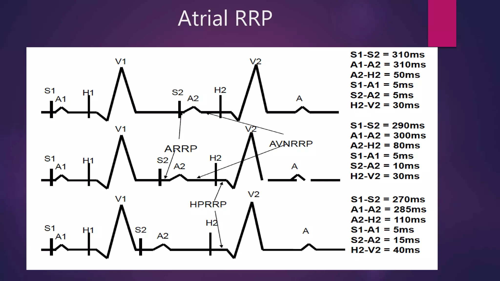
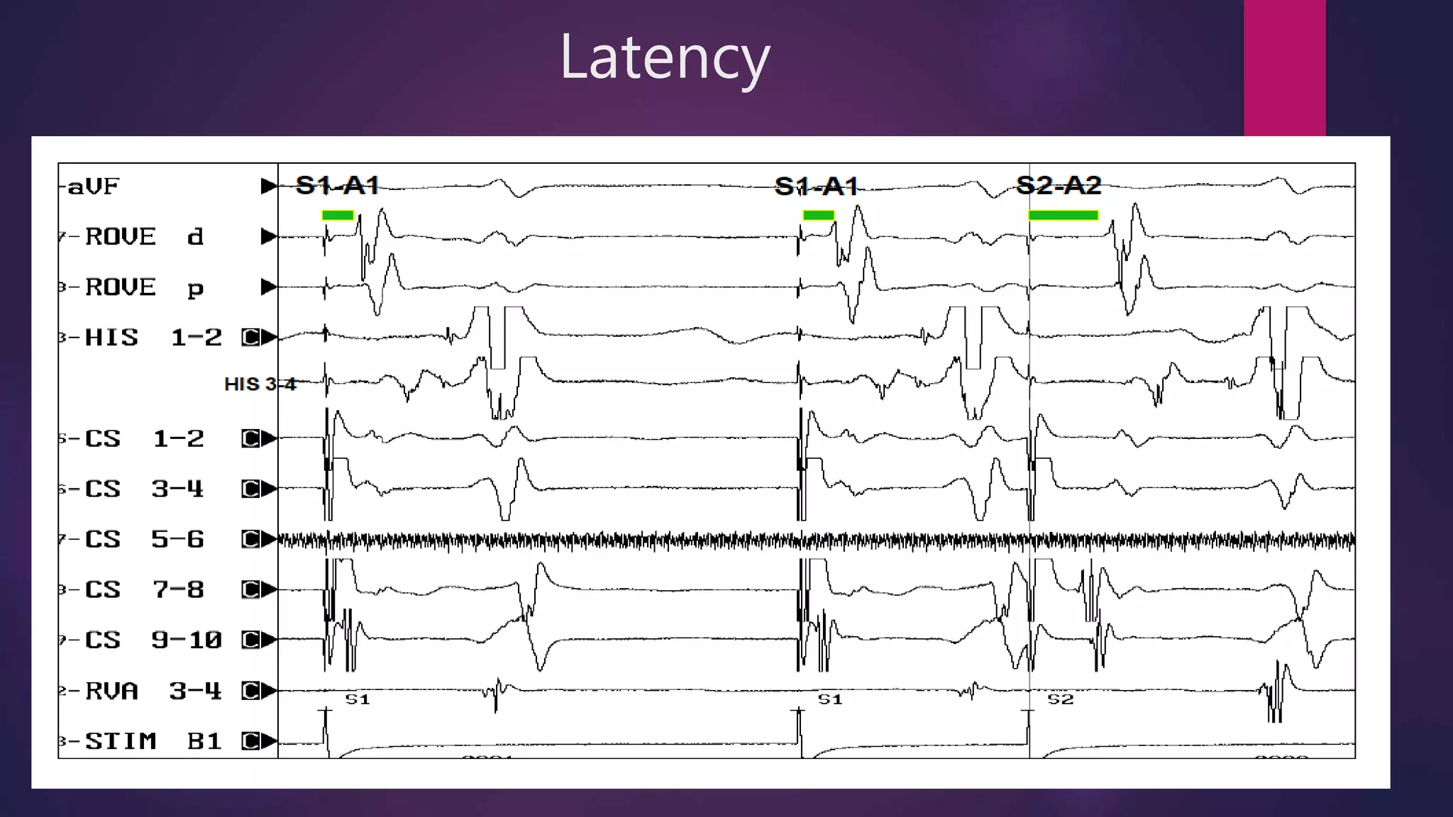
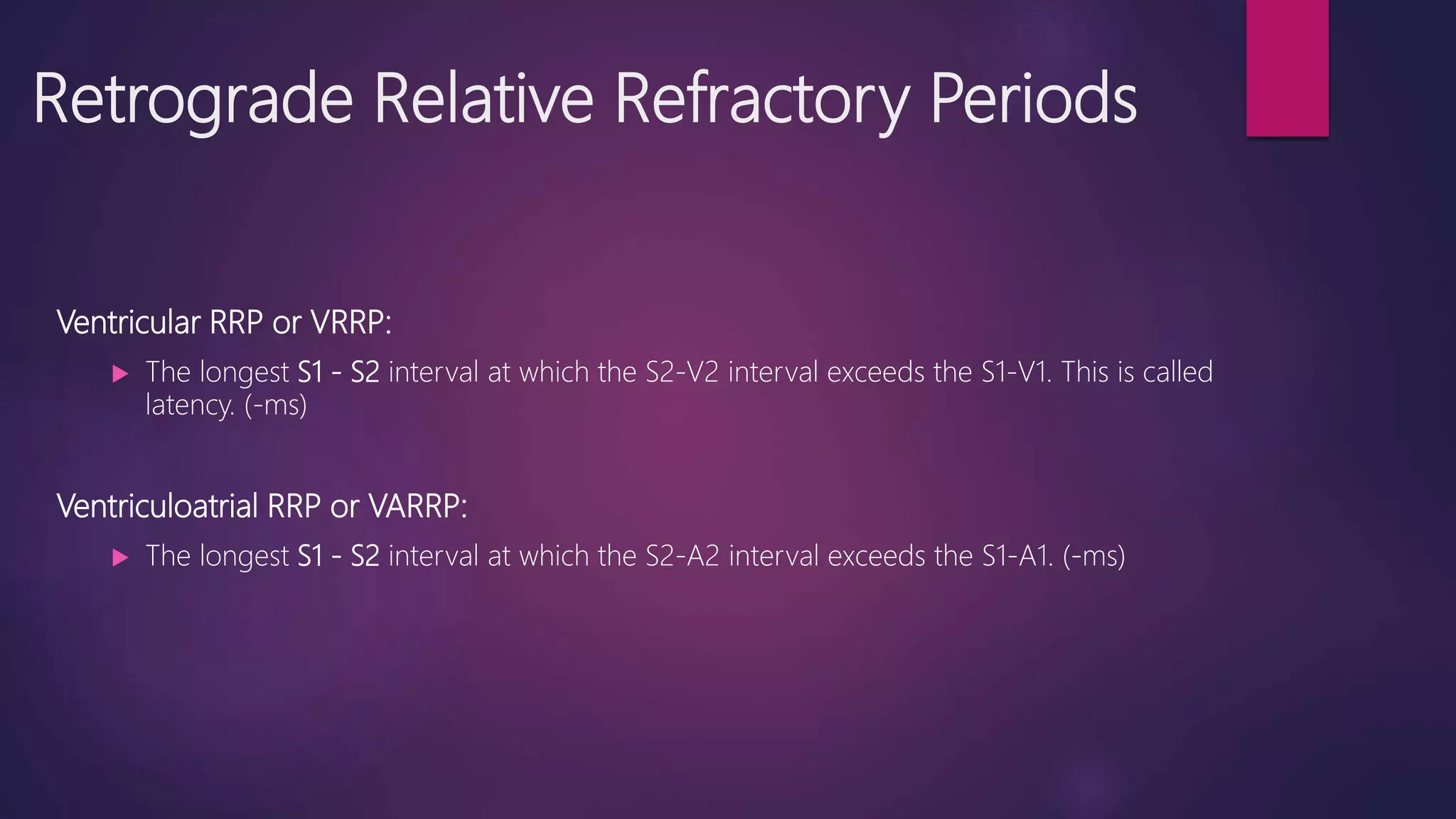
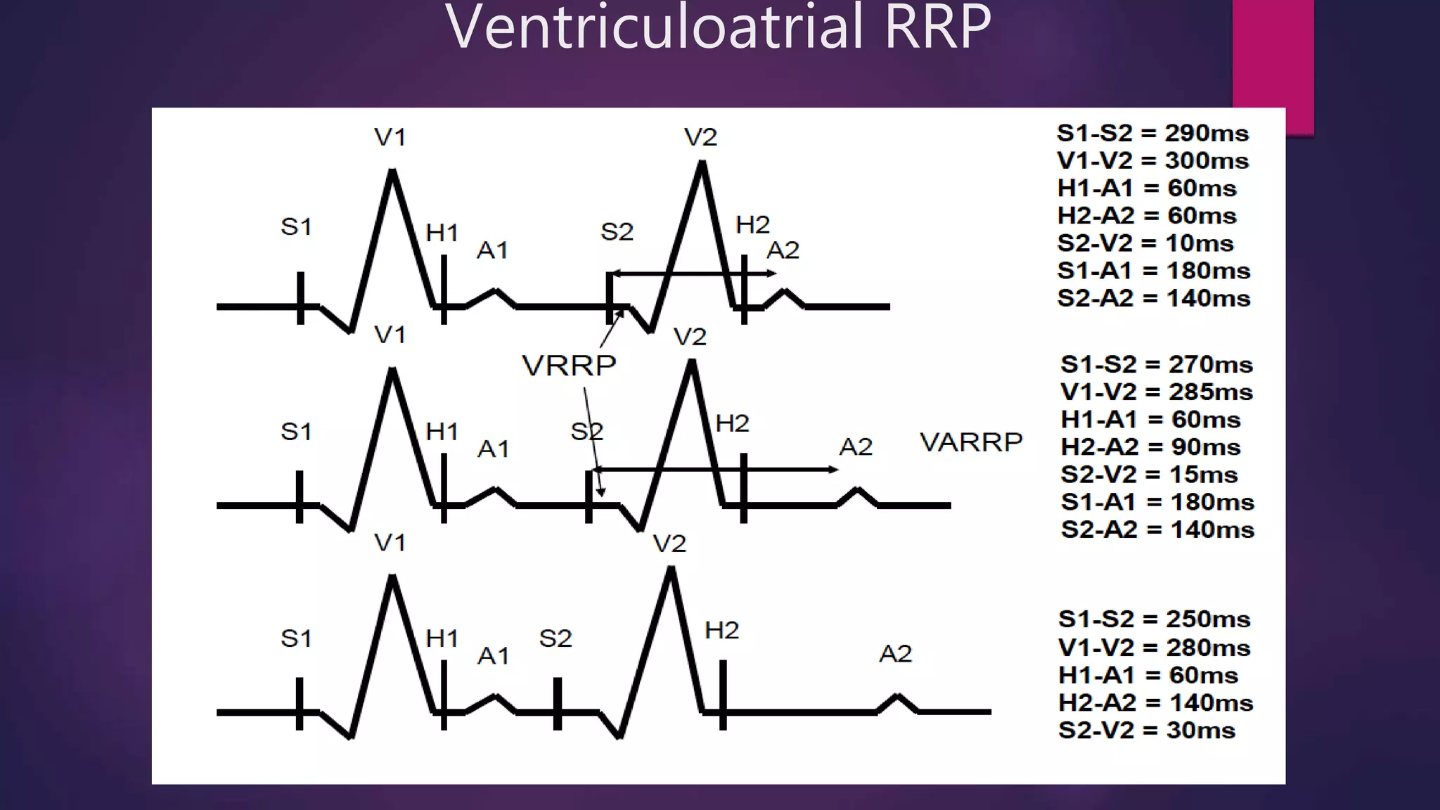


This document provides an overview of basic electrophysiology (EP) studies, which assess the heart's electrical system and conduction pathways. EP studies are used to diagnose and treat cardiac arrhythmias by characterizing atrial and ventricular properties, identifying accessory pathways, and guiding interventions like ablation. Key aspects covered include: indications for EP studies; equipment used; catheter placement; measurement of intervals like AH and HV; pacing protocols to assess refractory periods; and response patterns to extra stimuli.


![ECG & Heart block [doctors online]](https://cdn.slidesharecdn.com/ss_thumbnails/ecgheartblockdoctorsonline-131111054313-phpapp01-thumbnail.jpg?width=640&height=640&fit=bounds)


![EPS part 2 FINAL [Autosaved].pptx........](https://cdn.slidesharecdn.com/ss_thumbnails/epspart2finalautosaved-250127140443-78c2d1e9-thumbnail.jpg?width=640&height=640&fit=bounds)


