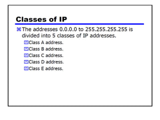
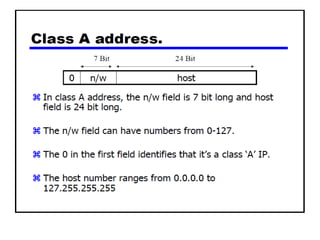
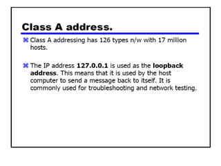
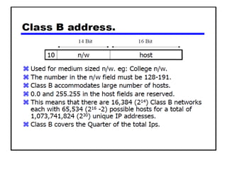
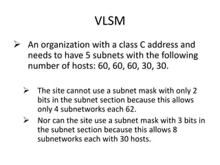
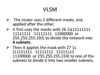
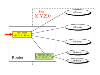
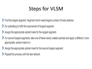
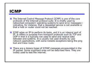
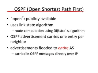
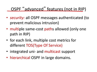
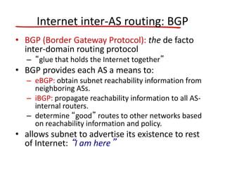
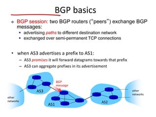
The document discusses several networking concepts:
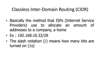
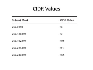
- Classless Inter-Domain Routing (CIDR) allows ISPs to allocate blocks of IP addresses to organizations in a more efficient manner than previous methods.
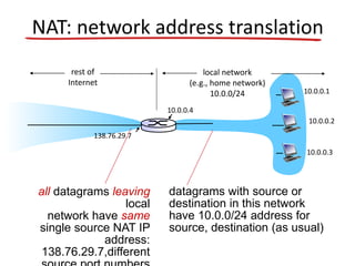
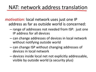
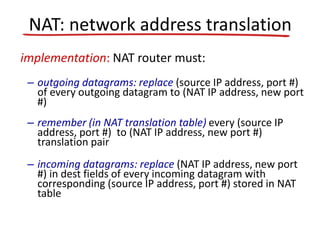
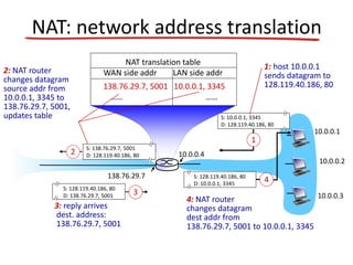
- Network Address Translation (NAT) allows a local network to use private IP address ranges behind a NAT-enabled router that maps the private addresses to a single public IP address for communication with external networks.
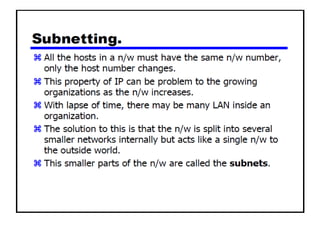
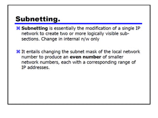
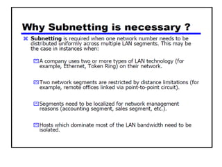
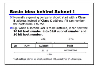
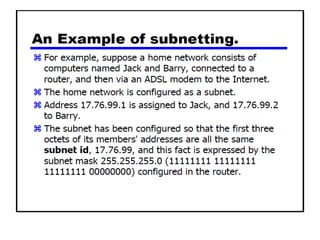
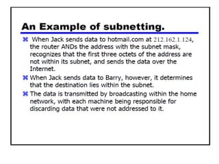
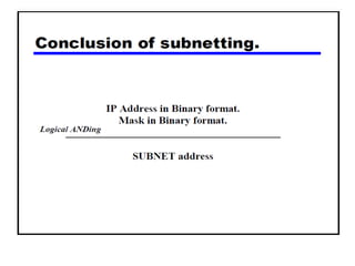
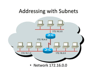
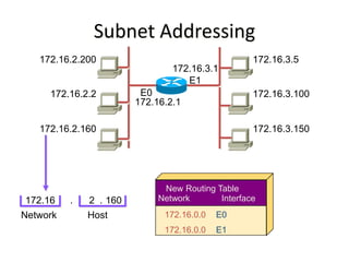
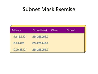
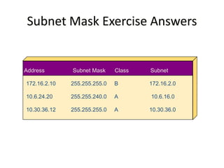
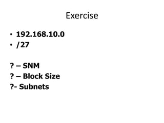
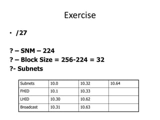
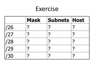
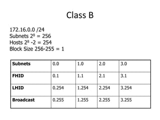
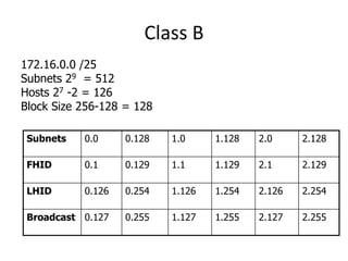
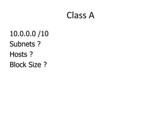
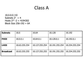
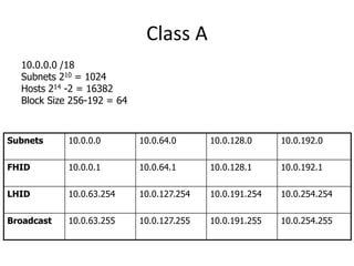
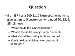
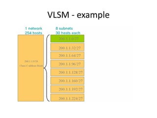
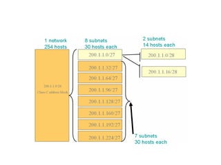
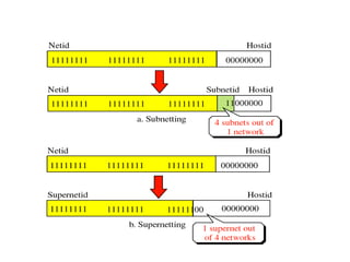
- Subnetting and Variable Length Subnet Masking (VLSM) allow networks to be divided into subnets to better utilize limited IP address blocks and assign addresses based on subnet needs.
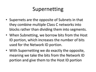
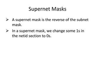
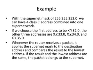
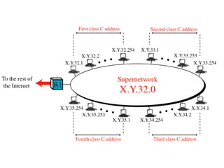
- Supernetting combines multiple classful network blocks into larger supernets to more efficiently use address space.


![IPv6: adoption
• US National Institutes of Standards estimate
[2013]:
– ~3% of industry IP routers
– ~11% of US gov’t routers
• Long (long!) time for deployment, use
– 20 years and counting!
– think of application-level changes in last 20 years:
WWW, Facebook, …
– Why?](https://image.slidesharecdn.com/unit9-150901045856-lva1-app6891/85/Network-Layer-111-320.jpg)


![[Ccna] subnetting & vlsm](https://cdn.slidesharecdn.com/ss_thumbnails/ccnasubnettingvlsm-100830021632-phpapp02-thumbnail.jpg?width=640&height=640&fit=bounds)