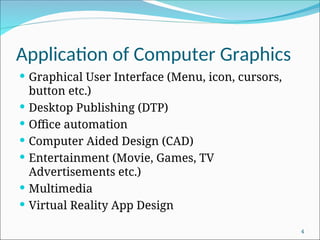
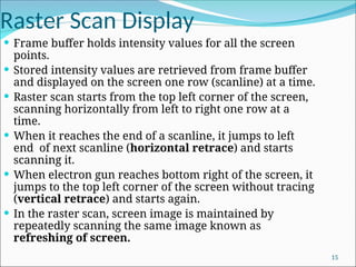
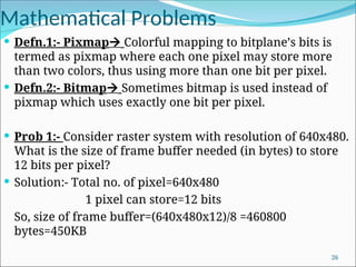
Introduction and Basics
Compiled & Prepared by
Prof. Abhijit Sarkar
IEM, Salt Lake
1
Introduction
 It involves display, manipulation & storage of
pictures for proper visualization using a
computer
 It provides a set of tools to create pictures and to
interact with them in natural ways.
2
Components of Computer Graphics
 Host computer with support of fast processor.
 Large memory
 Frame buffer
 Display devices (color monitors, LCD monitors
etc.)
 Input devices (mouse, keyboard, touch screen
etc.)
 Output devices (printers, plotters etc.)
3
Application of Computer Graphics
 Graphical User Interface (Menu, icon, cursors,
button etc.)
 Desktop Publishing (DTP)
 Office automation
 Computer Aided Design (CAD)
 Entertainment (Movie, Games, TV
Advertisements etc.)
 Multimedia
 Virtual Reality App Design
4
Cathode Ray Tube (CRT)
5
Cathode Ray Tube (CRT)
6
CRT Working Principle
 Primary components of an electron gun in a CRT are the
heated metal cathode & a control grid.
 Heat is supplied to the cathode by directing a current
through a coil of wire (filament).
 This causes electron to be “boiled off” the hot cathode
surface.
 The free, negatively charged electrons are then
accelerated toward the phosphor coating by a high +ve
voltage.
 A beam of electrons (cathode ray) emitted by an electron
gun, passes through focusing & deflection systems that
direct the beam toward specified position on the phosphor
coated screen.
7
CRT Working Principle
 Intensity of the electron beam is controlled by setting
voltage levels on the control grid.
 Focusing system forces the electron beam to converge
into a small spot as it strikes the phosphor.
 Horizontal & vertical movement of the electron beam
is controlled by horizontal & vertical deflection plate
respectively.
 Accelerating anode controls the velocity of the electron
beam.
 After passing through focusing system & deflection
system, when the electron in the beam collide with
phosphor coating, they are stopped & their kinetic
energy is absorbed by the phosphor.
8
CRT Working Principle
 Part of the beam energy is converted by friction into
heat energy, & the remainder causes electrons in the
phosphor atoms to move up to higher quantum
energy levels.
 After a short time, the “excited” phosphor electrons
begins dropping back to their stable ground state,
giving up their extra energy as small quantum's of
light energy.
 Because the light emitted by the phosphor fades very
rapidly, to keep the phosphor glowing, the picture is
redrawn repeatedly by quickly directing the electron
beam back over the same point. This type of display is
known as refresh CRT.
9
Important definition
 Persistence:- Time it takes the emitted light from the
screen to decay to 1/10th
of its original intensity.
 Aspect Ratio:- This number gives the ratio of horizontal
points to vertical points necessary to produce equal length
lines in both directions on the screen.
Width:height necessary to produce equal length lines.
E.g. 4:3, 16:9, 16:10 etc.
 Resolution:- The maximum no. of points that can be
displayed without overlap on a CRT.
Number of distinct pixels in each dimension that can be
displayed.
In digital measurement, display resolution would be given
in pixels per inch or cm.
Refresh Rate of CRT:- It is defined by the number of times
CRT screen is scanned by electron beam per unit time.
10
Random Scan System
11
Random Scan System
 Electron beam is moved along the particular
direction and length of line to be plotted.
 Application program is stored along with graphics
package.
 Commands are translated into display file by
package.
 Display file is accessed by display processor. And
line is drawn.
 It is designed for line drawing applications and
cannot display realistic shaded scenes.
12
Raster Scan Display
Architecture of Raster Scan Display System
13
Raster Scan Display
 Electron beam is swept across the screen one row at a
time from top to bottom and from left to right.
 Entire screen is a matrix of phosphor dot(pixel).
 As the electron beam moves across each row, beam
intensity is turned on and off to create patterns of
illuminated spots.
 Picture definition is stored in a memory area called as
refresh or frame buffer.
14
Raster Scan Display
 Frame buffer holds intensity values for all the screen
points.
 Stored intensity values are retrieved from frame buffer
and displayed on the screen one row (scanline) at a time.
 Raster scan starts from the top left corner of the screen,
scanning horizontally from left to right one row at a
time.
 When it reaches the end of a scanline, it jumps to left
end of next scanline (horizontal retrace) and starts
scanning it.
 When electron gun reaches bottom right of the screen, it
jumps to the top left corner of the screen without tracing
(vertical retrace) and starts again.
 In the raster scan, screen image is maintained by
repeatedly scanning the same image known as
refreshing of screen.
15
Raster Scan Display
 On some raster scan system, each frame is
displayed in two passes using an interlaced
refresh procedure.
 In interlacing, instead of refreshing every line, the
electron guns sweep alternate lines on each pass.
In the first pass, odd numbered lines are
refreshed, in the seconds pass even numbered
lines are refreshed.
 Interlacing allows the refresh rate to be doubled
because only half the screen is redrawn at a time.
 This system is well suited for realistic display of
screens containing shading and color patterns.
16
Random Scan Vs. Raster Scan
Random or Vector Scan Display Raster Scan Display
Beam is moved between the
endpoints of graphics
primitives.
Beam is moved all over the
screen.
Scan conversion is not required. Graphics primitives must be scan
converted into corresponding
pixels.
Draws continuous and smooth
lines.
Can display mathematically
smooth lines only by
approximating them with pixels
on the raster grid.
Cost is more. Cost is less.
Only draws lines. It has the ability to display areas
filled with solid colors or patterns
or shaded areas.
Don’t uses interlacing. It uses interlacing.
Line drawing system Point plotting system.
Resolution is high Resolution is low 17
Color CRT Monitor Types
Beam Penetration Method:-
 It is used in random scan monitors.
 Two layers of phosphor, red & green,
are coated onto the inside of the CRT
screen.
 Displayed color depends on how far the
electron beam penetrates into the
phosphor layers.
 A beam of slow electrons excites only
the outer red layer.
 A beam of very fast electrons penetrates
through the red layers and excites the
inner green layer.
 At intermediate beam speed,
combination of red & green light,
orange & yellow are emitted.
 Drawback:- Only 4 colors are possible
and quality of pictures is not as good as
with other method. 18
Color CRT Monitor Types
Shadow-Mask Method:-
 It is used in raster scan system (including color TV)
 It has 3 phosphor color dots at each pixel position, known as
triad.
 One phosphor dot emits a red light, another emits a green light
and the third emits a blue light.
 It has 3 electron guns, one for each color dot.
(TRIAD)
19
Color CRT Monitor Types
Shadow-Mask Method (cont.):-
 Also it has shadow mask grid just behind the phosphor coated screen.
 The three electron beams are deflected and focused as a group onto
the shadow mask, which contains a series of holes aligned with the
phosphor dot patterns.
 When the three beams pass through a hole in the mask, they activate
a dot triangle, which appears as a small color spot on the screen.
 We obtain color variations by varying the intensity levels on the
three electron beams as follows-
20
Simple Color Frame Buffer
 It uses 1 bit-plane per color which gives a 3 bit-plane
frame buffer or refresh buffer.
 Number of cells in each bit-plane depends on
resolution of screen. If resolution is a x b, then
number of cells in each bit-plane is a x b. ( a columns,
b rows)
 Picture definition is stored in binary 1 and 0 in each
cell of each bit-plane.
21
Simple Color Frame Buffer
 To illuminate a particular pixel, the particular cell with pixel’s
coordinate or position is accessed from each bit-plane. At a time,
only one particular cell location from each bit-plane can be
accessed.
 Retrieved binary data from each bit-plane cell is stored in
corresponding attached register.
 Register is connected to DAC (Digital-to-analog converter)
 If DAC receives “1” then it will produce analog voltage & feed it to
the corresponding attached electron gun. Otherwise, it doesn’t
generate any voltage causing the corresponding electron gun to not
fire electron beam.
 In accordance to the 3 dedicated electron gun’s firing of electron
beam, appropriate color dot is illuminated.
22
Full Color Frame Buffer
23
Full Color Frame Buffer
 Typically, 8 bit planes per color is used, which
gives a 24-bit plane frame buffer.
 Each group of bit-planes drives an 8 bit DAC.
 Each group generates 28
 256 shades of
intensities of R,G, B
 We obtain 224
 16,777,216 possible colors
24
Use of Lookup Table
 N bit plane color frame buffer with W-bit wide LUT is used
 Typically, W>N
 N bit register content acts as an index into the LUT
 Out of 2W
possible intensities, that are available, only 2N
different intensities are usable at any time.
25
Mathematical Problems
 Defn.1:- Pixmap Colorful mapping to bitplane’s bits is
termed as pixmap where each one pixel may store more
than two colors, thus using more than one bit per pixel.
 Defn.2:- Bitmap Sometimes bitmap is used instead of
pixmap which uses exactly one bit per pixel.
 Prob 1:- Consider raster system with resolution of 640x480.
What is the size of frame buffer needed (in bytes) to store
12 bits per pixel?
 Solution:- Total no. of pixel=640x480
1 pixel can store=12 bits
So, size of frame buffer=(640x480x12)/8 =460800
bytes=450KB
26
Mathematical Problems
 Prob 2:- Consider raster system with resolution
640x480. How many pixels could be accessed per
second if refresh rate is 60fps?
 Solution:- No. of pixels in one frame=640x480
Controller can access 60 frames per second.
Total no. of pixels accessed=640x480x60 per
second=18432000 per second
Access time per pixel=1/(640x480x60)=5.4x10-8
sec per
pixel
27
Mathematical Problems
 Prob 3:- How much time is spent scanning across each row of pixels
during screen refresh on a raster system with resolution of 1280x1024
and refresh rate 60 fps.
 Solution:- Resolution=1280x1024
No. of scan lines=1024
1 frame takes=1/60 seconds [1 frame consists of 1024 scan lines]
1024 scan lines takes =1/60 sec
1 scan line takes=1/(60x1024) =0.0000163 sec
Prob 4:- A raster color display processor supports a resolution of 1024x800
with upto 16 million colors simultaneously displayable. What will be the
approximate size (in bytes) of the frame buffer used in the display
processor?
Solution:- Total pixels=1024x800=819200
Generally, if each pixel requires 24 bits (3 bytes) to store color
information, then all possible combination of colors= 224
=1,67,77,216 = 16
million
Approx. size of frame buffer= 8,19,200x3 =24,57,600 bytes=2.4x10⁶
bytes
28

1.computer graphic introdictionand basic compiledintro_Graphics.ppt

  • 1.
    Introduction and Basics Compiled& Prepared by Prof. Abhijit Sarkar IEM, Salt Lake 1
  • 2.
    Introduction  It involvesdisplay, manipulation & storage of pictures for proper visualization using a computer  It provides a set of tools to create pictures and to interact with them in natural ways. 2
  • 3.
    Components of ComputerGraphics  Host computer with support of fast processor.  Large memory  Frame buffer  Display devices (color monitors, LCD monitors etc.)  Input devices (mouse, keyboard, touch screen etc.)  Output devices (printers, plotters etc.) 3
  • 4.
    Application of ComputerGraphics  Graphical User Interface (Menu, icon, cursors, button etc.)  Desktop Publishing (DTP)  Office automation  Computer Aided Design (CAD)  Entertainment (Movie, Games, TV Advertisements etc.)  Multimedia  Virtual Reality App Design 4
  • 5.
  • 6.
  • 7.
    CRT Working Principle Primary components of an electron gun in a CRT are the heated metal cathode & a control grid.  Heat is supplied to the cathode by directing a current through a coil of wire (filament).  This causes electron to be “boiled off” the hot cathode surface.  The free, negatively charged electrons are then accelerated toward the phosphor coating by a high +ve voltage.  A beam of electrons (cathode ray) emitted by an electron gun, passes through focusing & deflection systems that direct the beam toward specified position on the phosphor coated screen. 7
  • 8.
    CRT Working Principle Intensity of the electron beam is controlled by setting voltage levels on the control grid.  Focusing system forces the electron beam to converge into a small spot as it strikes the phosphor.  Horizontal & vertical movement of the electron beam is controlled by horizontal & vertical deflection plate respectively.  Accelerating anode controls the velocity of the electron beam.  After passing through focusing system & deflection system, when the electron in the beam collide with phosphor coating, they are stopped & their kinetic energy is absorbed by the phosphor. 8
  • 9.
    CRT Working Principle Part of the beam energy is converted by friction into heat energy, & the remainder causes electrons in the phosphor atoms to move up to higher quantum energy levels.  After a short time, the “excited” phosphor electrons begins dropping back to their stable ground state, giving up their extra energy as small quantum's of light energy.  Because the light emitted by the phosphor fades very rapidly, to keep the phosphor glowing, the picture is redrawn repeatedly by quickly directing the electron beam back over the same point. This type of display is known as refresh CRT. 9
  • 10.
    Important definition  Persistence:-Time it takes the emitted light from the screen to decay to 1/10th of its original intensity.  Aspect Ratio:- This number gives the ratio of horizontal points to vertical points necessary to produce equal length lines in both directions on the screen. Width:height necessary to produce equal length lines. E.g. 4:3, 16:9, 16:10 etc.  Resolution:- The maximum no. of points that can be displayed without overlap on a CRT. Number of distinct pixels in each dimension that can be displayed. In digital measurement, display resolution would be given in pixels per inch or cm. Refresh Rate of CRT:- It is defined by the number of times CRT screen is scanned by electron beam per unit time. 10
  • 11.
  • 12.
    Random Scan System Electron beam is moved along the particular direction and length of line to be plotted.  Application program is stored along with graphics package.  Commands are translated into display file by package.  Display file is accessed by display processor. And line is drawn.  It is designed for line drawing applications and cannot display realistic shaded scenes. 12
  • 13.
    Raster Scan Display Architectureof Raster Scan Display System 13
  • 14.
    Raster Scan Display Electron beam is swept across the screen one row at a time from top to bottom and from left to right.  Entire screen is a matrix of phosphor dot(pixel).  As the electron beam moves across each row, beam intensity is turned on and off to create patterns of illuminated spots.  Picture definition is stored in a memory area called as refresh or frame buffer. 14
  • 15.
    Raster Scan Display Frame buffer holds intensity values for all the screen points.  Stored intensity values are retrieved from frame buffer and displayed on the screen one row (scanline) at a time.  Raster scan starts from the top left corner of the screen, scanning horizontally from left to right one row at a time.  When it reaches the end of a scanline, it jumps to left end of next scanline (horizontal retrace) and starts scanning it.  When electron gun reaches bottom right of the screen, it jumps to the top left corner of the screen without tracing (vertical retrace) and starts again.  In the raster scan, screen image is maintained by repeatedly scanning the same image known as refreshing of screen. 15
  • 16.
    Raster Scan Display On some raster scan system, each frame is displayed in two passes using an interlaced refresh procedure.  In interlacing, instead of refreshing every line, the electron guns sweep alternate lines on each pass. In the first pass, odd numbered lines are refreshed, in the seconds pass even numbered lines are refreshed.  Interlacing allows the refresh rate to be doubled because only half the screen is redrawn at a time.  This system is well suited for realistic display of screens containing shading and color patterns. 16
  • 17.
    Random Scan Vs.Raster Scan Random or Vector Scan Display Raster Scan Display Beam is moved between the endpoints of graphics primitives. Beam is moved all over the screen. Scan conversion is not required. Graphics primitives must be scan converted into corresponding pixels. Draws continuous and smooth lines. Can display mathematically smooth lines only by approximating them with pixels on the raster grid. Cost is more. Cost is less. Only draws lines. It has the ability to display areas filled with solid colors or patterns or shaded areas. Don’t uses interlacing. It uses interlacing. Line drawing system Point plotting system. Resolution is high Resolution is low 17
  • 18.
    Color CRT MonitorTypes Beam Penetration Method:-  It is used in random scan monitors.  Two layers of phosphor, red & green, are coated onto the inside of the CRT screen.  Displayed color depends on how far the electron beam penetrates into the phosphor layers.  A beam of slow electrons excites only the outer red layer.  A beam of very fast electrons penetrates through the red layers and excites the inner green layer.  At intermediate beam speed, combination of red & green light, orange & yellow are emitted.  Drawback:- Only 4 colors are possible and quality of pictures is not as good as with other method. 18
  • 19.
    Color CRT MonitorTypes Shadow-Mask Method:-  It is used in raster scan system (including color TV)  It has 3 phosphor color dots at each pixel position, known as triad.  One phosphor dot emits a red light, another emits a green light and the third emits a blue light.  It has 3 electron guns, one for each color dot. (TRIAD) 19
  • 20.
    Color CRT MonitorTypes Shadow-Mask Method (cont.):-  Also it has shadow mask grid just behind the phosphor coated screen.  The three electron beams are deflected and focused as a group onto the shadow mask, which contains a series of holes aligned with the phosphor dot patterns.  When the three beams pass through a hole in the mask, they activate a dot triangle, which appears as a small color spot on the screen.  We obtain color variations by varying the intensity levels on the three electron beams as follows- 20
  • 21.
    Simple Color FrameBuffer  It uses 1 bit-plane per color which gives a 3 bit-plane frame buffer or refresh buffer.  Number of cells in each bit-plane depends on resolution of screen. If resolution is a x b, then number of cells in each bit-plane is a x b. ( a columns, b rows)  Picture definition is stored in binary 1 and 0 in each cell of each bit-plane. 21
  • 22.
    Simple Color FrameBuffer  To illuminate a particular pixel, the particular cell with pixel’s coordinate or position is accessed from each bit-plane. At a time, only one particular cell location from each bit-plane can be accessed.  Retrieved binary data from each bit-plane cell is stored in corresponding attached register.  Register is connected to DAC (Digital-to-analog converter)  If DAC receives “1” then it will produce analog voltage & feed it to the corresponding attached electron gun. Otherwise, it doesn’t generate any voltage causing the corresponding electron gun to not fire electron beam.  In accordance to the 3 dedicated electron gun’s firing of electron beam, appropriate color dot is illuminated. 22
  • 23.
  • 24.
    Full Color FrameBuffer  Typically, 8 bit planes per color is used, which gives a 24-bit plane frame buffer.  Each group of bit-planes drives an 8 bit DAC.  Each group generates 28  256 shades of intensities of R,G, B  We obtain 224  16,777,216 possible colors 24
  • 25.
    Use of LookupTable  N bit plane color frame buffer with W-bit wide LUT is used  Typically, W>N  N bit register content acts as an index into the LUT  Out of 2W possible intensities, that are available, only 2N different intensities are usable at any time. 25
  • 26.
    Mathematical Problems  Defn.1:-Pixmap Colorful mapping to bitplane’s bits is termed as pixmap where each one pixel may store more than two colors, thus using more than one bit per pixel.  Defn.2:- Bitmap Sometimes bitmap is used instead of pixmap which uses exactly one bit per pixel.  Prob 1:- Consider raster system with resolution of 640x480. What is the size of frame buffer needed (in bytes) to store 12 bits per pixel?  Solution:- Total no. of pixel=640x480 1 pixel can store=12 bits So, size of frame buffer=(640x480x12)/8 =460800 bytes=450KB 26
  • 27.
    Mathematical Problems  Prob2:- Consider raster system with resolution 640x480. How many pixels could be accessed per second if refresh rate is 60fps?  Solution:- No. of pixels in one frame=640x480 Controller can access 60 frames per second. Total no. of pixels accessed=640x480x60 per second=18432000 per second Access time per pixel=1/(640x480x60)=5.4x10-8 sec per pixel 27
  • 28.
    Mathematical Problems  Prob3:- How much time is spent scanning across each row of pixels during screen refresh on a raster system with resolution of 1280x1024 and refresh rate 60 fps.  Solution:- Resolution=1280x1024 No. of scan lines=1024 1 frame takes=1/60 seconds [1 frame consists of 1024 scan lines] 1024 scan lines takes =1/60 sec 1 scan line takes=1/(60x1024) =0.0000163 sec Prob 4:- A raster color display processor supports a resolution of 1024x800 with upto 16 million colors simultaneously displayable. What will be the approximate size (in bytes) of the frame buffer used in the display processor? Solution:- Total pixels=1024x800=819200 Generally, if each pixel requires 24 bits (3 bytes) to store color information, then all possible combination of colors= 224 =1,67,77,216 = 16 million Approx. size of frame buffer= 8,19,200x3 =24,57,600 bytes=2.4x106 bytes 28