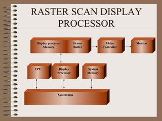
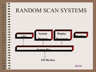
DISPLAY SYSTEMS
RASTER SCAN SYSTEMS
• Interactive raster graphics employ several
  processing units
• Apart from CPU, a special purpose
  processor called video controller or display
  controller  control operation of the
  display device
• Simple raster graphics system
VIDEO CONTROLLER
• Fixed area of system memory reserved for
  frame buffer
• Video controller given direct access to
  frame buffer to refresh the screen
• Coordinate origin is defined at lower left
  corner
• Scan lines labeled from ymax at the top of
  the screen to 0 at the bottom
BASIC REFRESH
                           OPERATIONS
                                                    • Registers store the
                               Horizontal and
       Raster Scan            Vertical Deflection
       Generator                   Voltages
                                                      coordinates of the
                                                      screen pixels
  X
Register
                Y
              Register                              • X  0; Y  ymax
                                                       • Value stored in frame
       Memory               Pixel
                                             Intensity   buffer is used to set
       Address             Register
                                                         the intensity of the
                                                         CRT
                 Frame
                 Buffer
• X incremented by 1; process repeated for
  each pixel along the scan line
• Procedure is repeated for each scan line
• After cycling through all pixels, refresh
  process starts over
• To speed up processing, multiple pixel
  intensities are retrieved
• Stored in separate register to control the
  CRT for group of adjacent pixels
• In high quality systems, two frame buffers
  are provided
• One used for refreshing and other is filled
  with intensity values
• Thus provides a fast mechanism for real
  time animation – different views
  successively loaded into refresh buffers
RASTER SCAN DISPLAY
    PROCESSOR
 Display processor          Frame               Video      Monitor
     Memory                 Buffer            Controller


CPU             Display              System
               Processor             Memory


               System bus
RASTER SCAN DISPLAY
       PROCESSOR
• Separate display processor free CPU from
  graphics chores
• Separate display processor memory also
  provided
• Major task  digitizing picture definition
  into set of pixel intensities : scan
  conversion
• Display processor perform additional
  operations like generating various line
  styles, displaying various color areas and
  performing certain manipulations
• To reduce memory requirements
       Run length encoding : Store each
  scan line as a set of integer
       Cell encoding : Encode as a set of
  rectangular areas
RANDOM SCAN SYSTEMS
• Organization
• Application program is input and stored in
  system memory along with the graphics
  package
• Graphics commands in the application
  pgm is translated by graphics package into
  a display file which is accessed by display
  processor
• Display processor  DPU or graphics
  controller
SIMPLE RASTER SYSTEM


        System            Video
 CPU                                 Monitor
       Memory           Controller


       System Bus


          I/O Devices

                                     BACK
COMMON ORGANIZATION
 FOR RASTER SYSTEMS


      System   Frame       Video
CPU                                     Monitor
      Memory   Buffer    Controller


        System Bus


           I/O Devices
                                      BACK
RANDOM SCAN SYSTEMS


        System          Display
 CPU                                Monitor
       Memory           Processor


       System Bus


          I/O Devices

                                    BACK

Display Systems

  • 1.
  • 2.
    RASTER SCAN SYSTEMS •Interactive raster graphics employ several processing units • Apart from CPU, a special purpose processor called video controller or display controller  control operation of the display device • Simple raster graphics system
  • 3.
    VIDEO CONTROLLER • Fixedarea of system memory reserved for frame buffer • Video controller given direct access to frame buffer to refresh the screen • Coordinate origin is defined at lower left corner • Scan lines labeled from ymax at the top of the screen to 0 at the bottom
  • 4.
    BASIC REFRESH OPERATIONS • Registers store the Horizontal and Raster Scan Vertical Deflection Generator Voltages coordinates of the screen pixels X Register Y Register • X  0; Y  ymax • Value stored in frame Memory Pixel Intensity buffer is used to set Address Register the intensity of the CRT Frame Buffer
  • 5.
    • X incrementedby 1; process repeated for each pixel along the scan line • Procedure is repeated for each scan line • After cycling through all pixels, refresh process starts over • To speed up processing, multiple pixel intensities are retrieved • Stored in separate register to control the CRT for group of adjacent pixels
  • 6.
    • In highquality systems, two frame buffers are provided • One used for refreshing and other is filled with intensity values • Thus provides a fast mechanism for real time animation – different views successively loaded into refresh buffers
  • 7.
    RASTER SCAN DISPLAY PROCESSOR Display processor Frame Video Monitor Memory Buffer Controller CPU Display System Processor Memory System bus
  • 8.
    RASTER SCAN DISPLAY PROCESSOR • Separate display processor free CPU from graphics chores • Separate display processor memory also provided • Major task  digitizing picture definition into set of pixel intensities : scan conversion
  • 9.
    • Display processorperform additional operations like generating various line styles, displaying various color areas and performing certain manipulations • To reduce memory requirements  Run length encoding : Store each scan line as a set of integer  Cell encoding : Encode as a set of rectangular areas
  • 10.
    RANDOM SCAN SYSTEMS •Organization • Application program is input and stored in system memory along with the graphics package • Graphics commands in the application pgm is translated by graphics package into a display file which is accessed by display processor • Display processor  DPU or graphics controller
  • 12.
    SIMPLE RASTER SYSTEM System Video CPU Monitor Memory Controller System Bus I/O Devices BACK
  • 13.
    COMMON ORGANIZATION FORRASTER SYSTEMS System Frame Video CPU Monitor Memory Buffer Controller System Bus I/O Devices BACK
  • 14.
    RANDOM SCAN SYSTEMS System Display CPU Monitor Memory Processor System Bus I/O Devices BACK