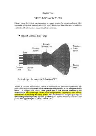
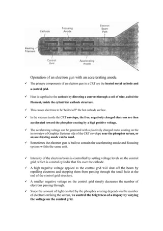
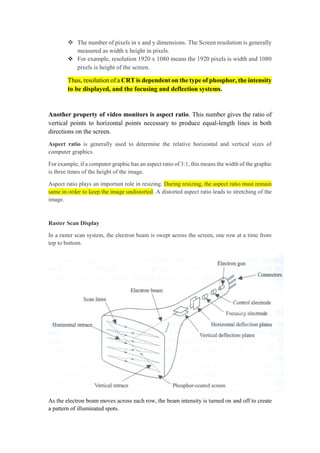
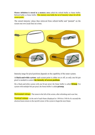
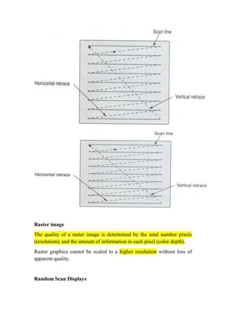
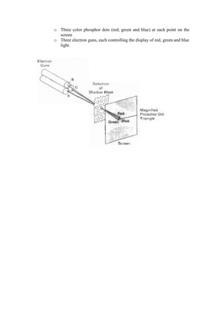
Chapter Two
VIDEO DISPLAY DEVICES
Primary output device in a graphics system is a video monitor.The operation of most video
monitors is basedon the standard cathode-raytube (CRT)design, but severalother technologies
exist and solid-state monitors may eventually predominate.
 Refresh Cathode-Ray Tubes
Basic design of a magnetic deflection CRT
A beam of electrons (cathode rays), emitted by an electron gun, passes through focusing and
deflection systems that direct the beam toward specified positions on the phosphor-coated
screen. The phosphor then emits a small spot of light at each position contacted by the
electronbeam.Because the lightemittedbythe phosphorfades veryrapidly, some method
is needed for maintaining the screen picture. One way to keep the phosphor glowing is to
redraw the picture repeatedly by quickly directing the electron beam back over the same
points. This type ofdisplay is called a refresh CRT.
Operation of an electron gun with an accelerating anode.
 The primary components of an electron gun in a CRT are the heated metal cathode and
a control grid.
 Heat is supplied to the cathode by directing a current through a coil ofwire, called the
filament, inside the cylindrical cathode structure.
 This causes electrons to be 'boiled off" the hot cathode surface.
 In the vacuum inside the CRT envelope, the free, negatively charged electrons are then
accelerated toward the phosphor coating by a high positive voltage.
 The accelerating voltage can be generated with a positively charged metal coating on the
in overview of Graphics Systems side of the CRT envelope near the phosphor screen, or
an accelerating anode can be used.
 Sometimes the electron gun is built to contain the accelerating anode and focusing
system within the same unit.
 Intensity of the electron beam is controlled by setting voltage levels on the control
grid, which is a metal cylinder that fits over the cathode.
 A high negative voltage applied to the control grid will shut off the beam by
repelling electrons and stopping them from passing through the small hole at the
end of the control grid structure.
 A smaller negative voltage on the control grid simply decreases the number of
electrons passing through.
 Since the amount of light emitted by the phosphor coating depends on the number
of electrons striking the screen, we control the brightness of a display by varying
the voltage on the control grid.
 The focusing system in a CRT is needed to force the electron beam
to converge into a small spotas it strikes the phosphor. Otherwise, the
electrons would repel each other, and the beam would spread out as it
approaches the screen. Focusing is accomplished with either electric or
magnetic fields.
 Electrostatic focusing is commonly used in television and computer graphics
monitors. With electrostatic focusing, the electron beam passes through a
positively charged metal cylinder that forms an electrostatic lens.
 The action of the electrostatic lens focusesthe electron beam at the centerof the screen,
in exactly the same way that an optical lens focuses a beam of light at a particular focal
distance.
 Magnetic lens focusing produces the smallest spot size on the screen and is used in
special purpose devices. E.g. Electron microscope
 Additional focusing hardware is used in high-precision systems to keep the beam in
focus at all screen positions.
 The distance that the electron beam must travel to different points on the screen varies
because the radius of curvature for most CRTs is greater than the distance from
the focusing system to the screen center.
 Therefore,the electron beam will be focused properly only at the center of the screen.
 As the beam moves to the outer edges of the screen, displayed images become blurred.
 To compensate for this, the system can adjust the focusing according to the screen
position of the beam.
 Different kinds of phosphors are available for use in a CRT.
 Besides color, a major difference betweenphosphors is their persistence: how long they
continue to emit light (that is, have excited electrons returning to the ground state)after
the CRT beam is removed.
 Persistence is defined as the time it takes the emitted light from the screen to decay to
one-tenth of its original intensity.
 Lower- persistence phosphors require higher refresh rates to maintain a picture on the
screen without flicker.
 A phosphor with low persistence is useful for animation; a high-persistence phosphor
is useful for displaying highly complex, static pictures.
 Although some phosphors have a persistence greater than 1 second, graphics monitors
are usually constructed with a persistence in the range from 10 to 60 microseconds.
The maximum number of points that can be displayed without overlap on a CRT is referred
to as the resolution.
A computer screen uses millions of pixels to display images. These pixels
are arranged in a grid horizontally and vertically. The number of pixels
horizontally and vertically is shown as the screen resolution.
 The number of pixels in x and y dimensions. The Screen resolution is generally
measured as width x height in pixels.
 For example, resolution 1920 x 1080 means the 1920 pixels is width and 1080
pixels is height of the screen.
Thus, resolution of a CRT is dependent on the type of phosphor, the intensity
to be displayed, and the focusing and deflection systems.
Another property of video monitors is aspect ratio. This number gives the ratio of
vertical points to horizontal points necessary to produce equal-length lines in both
directions on the screen.
Aspect ratio is generally used to determine the relative horizontal and vertical sizes of
computer graphics.
For example, if a computer graphic hasan aspectratio of 3:1, this meansthe width of the graphic
is three times of the height of the image.
Aspect ratio plays an important role in resizing. During resizing, the aspect ratio must remain
same in order to keep the image undistorted. A distorted aspect ratio leads to stretching of the
image.
Raster Scan Display
In a raster scan system, the electron beam is swept across the screen,one row at a time from
top to bottom.
As the electron beam moves across each row, the beam intensity is turned on and off to create
a pattern of illuminated spots.
Picture definition is stored in a memory area called the refresh buffer or frame buffer.
Refresh buffer or frame buffer: This memory area holds the set of intensity values for all the
screen points.
The stored intensity values then retrieved from refresh buffer and “painted” on the
screen one row (scan line) at a time.
Intensity range for pixel positions depends on the capability of the raster system.
A black-and-white system: each screen point is either on or off, so only one bit per
pixel is needed to control the intensity of screen positions.
On a black-and-white system with one bit per pixel, the frame buffer is called bitmap. For
system with multiple bits per pixel, the frame buffer is called pixmap.
Horizontal retrace: The return to the left of the screen,after refreshing each scan line.
Vertical retrace: At the end of each frame (displayed in 1/80 th to 1/60 th of a second) the
electron beam returns to the top left corner of the screen to begin the next frame.
Rasterimage
The quality of a raster image is determined by the total number pixels
(resolution), and the amount of information in each pixel (color depth).
Raster graphics cannot be scaled to a higher resolution without loss of
apparent quality.
Random ScanDisplays
Random scan display is the use of geometrical primitives such as points, lines, curves,
and polygons, which are all based upon mathematical equation.
Raster Scan is the representation of images as a collection of pixels (dots)
Random Scan Displays
In a random scan display, a CRT has the electron beam directed only to the parts of the
screen where a picture is to be drawn.
Random scan monitors draw a picture one line at a time (Vector display, Stroke –
writing or calligraphic displays).
Refresh rate depends on the number of lines to be displayed.
Picture definition is now stored as a line-drawing commands an area of memory
referred to as refresh display file (display list).
To display a picture, the system cycle through the set of commands in the display file,
drawing each component line in turn.
Random scan displays are designed to draw all the component lines of a picture 30 to
60 times each second.
ColorCRT Monitors
A CRT monitor displays color pictures by using a combination of phosphors that emit
different color lights.
Methods
 Beam Penetration
o Two layers of phosphor (red and green) are coated onto the inside of the
CRT screen.
o The display color depends on how far the electron beam penetrates into
the phosphor layers.
o The speed of the electrons, and the screen color at any point, is
controlled by the beam acceleration voltage.
 Used with random scan monitors
 Only four colors are possible (red, green, orange, and yellow).
 Quality of pictures is not as good as with other methods.
 Shadow Mask
o Shadow-mask methods are commonly used in raster scan systems
(including color TV) because they produce a much wider range of colors
than the beam- penetration method.
o A shadow-mask CRT has three phosphor color dots at each pixel
position.
o One phosphor dot emits a red light, another emits a green light,
o and the third emits a blue light. This type of CRT has three electron guns,
one for
o each color dot, and a shadow-mask grid just behind the phosphor-coated
screen.
o Three color phosphor dots (red, green and blue) at each point on the
screen
o Three electron guns, each controlling the display of red, green and blue
light.

Chapter two 1

  • 1.
    Chapter Two VIDEO DISPLAYDEVICES Primary output device in a graphics system is a video monitor.The operation of most video monitors is basedon the standard cathode-raytube (CRT)design, but severalother technologies exist and solid-state monitors may eventually predominate.  Refresh Cathode-Ray Tubes Basic design of a magnetic deflection CRT A beam of electrons (cathode rays), emitted by an electron gun, passes through focusing and deflection systems that direct the beam toward specified positions on the phosphor-coated screen. The phosphor then emits a small spot of light at each position contacted by the electronbeam.Because the lightemittedbythe phosphorfades veryrapidly, some method is needed for maintaining the screen picture. One way to keep the phosphor glowing is to redraw the picture repeatedly by quickly directing the electron beam back over the same points. This type ofdisplay is called a refresh CRT.
  • 2.
    Operation of anelectron gun with an accelerating anode.  The primary components of an electron gun in a CRT are the heated metal cathode and a control grid.  Heat is supplied to the cathode by directing a current through a coil ofwire, called the filament, inside the cylindrical cathode structure.  This causes electrons to be 'boiled off" the hot cathode surface.  In the vacuum inside the CRT envelope, the free, negatively charged electrons are then accelerated toward the phosphor coating by a high positive voltage.  The accelerating voltage can be generated with a positively charged metal coating on the in overview of Graphics Systems side of the CRT envelope near the phosphor screen, or an accelerating anode can be used.  Sometimes the electron gun is built to contain the accelerating anode and focusing system within the same unit.  Intensity of the electron beam is controlled by setting voltage levels on the control grid, which is a metal cylinder that fits over the cathode.  A high negative voltage applied to the control grid will shut off the beam by repelling electrons and stopping them from passing through the small hole at the end of the control grid structure.  A smaller negative voltage on the control grid simply decreases the number of electrons passing through.  Since the amount of light emitted by the phosphor coating depends on the number of electrons striking the screen, we control the brightness of a display by varying the voltage on the control grid.
  • 3.
     The focusingsystem in a CRT is needed to force the electron beam to converge into a small spotas it strikes the phosphor. Otherwise, the electrons would repel each other, and the beam would spread out as it approaches the screen. Focusing is accomplished with either electric or magnetic fields.  Electrostatic focusing is commonly used in television and computer graphics monitors. With electrostatic focusing, the electron beam passes through a positively charged metal cylinder that forms an electrostatic lens.  The action of the electrostatic lens focusesthe electron beam at the centerof the screen, in exactly the same way that an optical lens focuses a beam of light at a particular focal distance.  Magnetic lens focusing produces the smallest spot size on the screen and is used in special purpose devices. E.g. Electron microscope  Additional focusing hardware is used in high-precision systems to keep the beam in focus at all screen positions.  The distance that the electron beam must travel to different points on the screen varies because the radius of curvature for most CRTs is greater than the distance from the focusing system to the screen center.  Therefore,the electron beam will be focused properly only at the center of the screen.  As the beam moves to the outer edges of the screen, displayed images become blurred.  To compensate for this, the system can adjust the focusing according to the screen position of the beam.  Different kinds of phosphors are available for use in a CRT.  Besides color, a major difference betweenphosphors is their persistence: how long they continue to emit light (that is, have excited electrons returning to the ground state)after the CRT beam is removed.  Persistence is defined as the time it takes the emitted light from the screen to decay to one-tenth of its original intensity.  Lower- persistence phosphors require higher refresh rates to maintain a picture on the screen without flicker.  A phosphor with low persistence is useful for animation; a high-persistence phosphor is useful for displaying highly complex, static pictures.  Although some phosphors have a persistence greater than 1 second, graphics monitors are usually constructed with a persistence in the range from 10 to 60 microseconds. The maximum number of points that can be displayed without overlap on a CRT is referred to as the resolution. A computer screen uses millions of pixels to display images. These pixels are arranged in a grid horizontally and vertically. The number of pixels horizontally and vertically is shown as the screen resolution.
  • 4.
     The numberof pixels in x and y dimensions. The Screen resolution is generally measured as width x height in pixels.  For example, resolution 1920 x 1080 means the 1920 pixels is width and 1080 pixels is height of the screen. Thus, resolution of a CRT is dependent on the type of phosphor, the intensity to be displayed, and the focusing and deflection systems. Another property of video monitors is aspect ratio. This number gives the ratio of vertical points to horizontal points necessary to produce equal-length lines in both directions on the screen. Aspect ratio is generally used to determine the relative horizontal and vertical sizes of computer graphics. For example, if a computer graphic hasan aspectratio of 3:1, this meansthe width of the graphic is three times of the height of the image. Aspect ratio plays an important role in resizing. During resizing, the aspect ratio must remain same in order to keep the image undistorted. A distorted aspect ratio leads to stretching of the image. Raster Scan Display In a raster scan system, the electron beam is swept across the screen,one row at a time from top to bottom. As the electron beam moves across each row, the beam intensity is turned on and off to create a pattern of illuminated spots.
  • 5.
    Picture definition isstored in a memory area called the refresh buffer or frame buffer. Refresh buffer or frame buffer: This memory area holds the set of intensity values for all the screen points. The stored intensity values then retrieved from refresh buffer and “painted” on the screen one row (scan line) at a time. Intensity range for pixel positions depends on the capability of the raster system. A black-and-white system: each screen point is either on or off, so only one bit per pixel is needed to control the intensity of screen positions. On a black-and-white system with one bit per pixel, the frame buffer is called bitmap. For system with multiple bits per pixel, the frame buffer is called pixmap. Horizontal retrace: The return to the left of the screen,after refreshing each scan line. Vertical retrace: At the end of each frame (displayed in 1/80 th to 1/60 th of a second) the electron beam returns to the top left corner of the screen to begin the next frame.
  • 6.
    Rasterimage The quality ofa raster image is determined by the total number pixels (resolution), and the amount of information in each pixel (color depth). Raster graphics cannot be scaled to a higher resolution without loss of apparent quality. Random ScanDisplays
  • 7.
    Random scan displayis the use of geometrical primitives such as points, lines, curves, and polygons, which are all based upon mathematical equation. Raster Scan is the representation of images as a collection of pixels (dots) Random Scan Displays In a random scan display, a CRT has the electron beam directed only to the parts of the screen where a picture is to be drawn. Random scan monitors draw a picture one line at a time (Vector display, Stroke – writing or calligraphic displays). Refresh rate depends on the number of lines to be displayed. Picture definition is now stored as a line-drawing commands an area of memory referred to as refresh display file (display list). To display a picture, the system cycle through the set of commands in the display file, drawing each component line in turn. Random scan displays are designed to draw all the component lines of a picture 30 to 60 times each second. ColorCRT Monitors A CRT monitor displays color pictures by using a combination of phosphors that emit different color lights. Methods  Beam Penetration o Two layers of phosphor (red and green) are coated onto the inside of the CRT screen. o The display color depends on how far the electron beam penetrates into the phosphor layers. o The speed of the electrons, and the screen color at any point, is controlled by the beam acceleration voltage.  Used with random scan monitors  Only four colors are possible (red, green, orange, and yellow).  Quality of pictures is not as good as with other methods.  Shadow Mask o Shadow-mask methods are commonly used in raster scan systems (including color TV) because they produce a much wider range of colors than the beam- penetration method. o A shadow-mask CRT has three phosphor color dots at each pixel position. o One phosphor dot emits a red light, another emits a green light, o and the third emits a blue light. This type of CRT has three electron guns, one for o each color dot, and a shadow-mask grid just behind the phosphor-coated screen.
  • 8.
    o Three colorphosphor dots (red, green and blue) at each point on the screen o Three electron guns, each controlling the display of red, green and blue light.