Downloaded 89 times

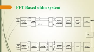
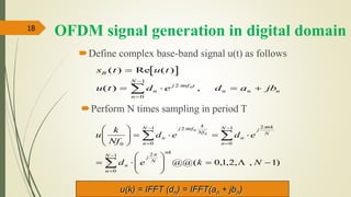
![OFDM Implementation
Signal
Mapper
(QPSK)
IFFT
Parallel-
to-Serial
Converter
Guard
Interval
Insertion
Serial-to-
Parallel
Converter
2d
1nd
Serial
Data
Input
1s
2s
1ns
x bits
D/A
&
Lowpass
Filter
1x 1d
2x
1nx
x= [1,0,1,1,0,0…] x1=[1,0]
x2=[1,1]
x3=[0,0]
……..
d1=[-1]
d2=[-i]
d3=[1]
……..](https://image.slidesharecdn.com/ofdm-170303183334/85/orthogonal-frequency-division-multiplexing-OFDM-8-320.jpg)
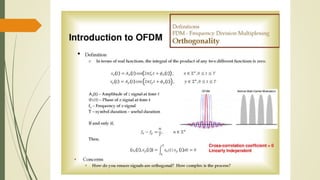
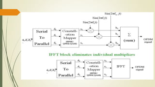
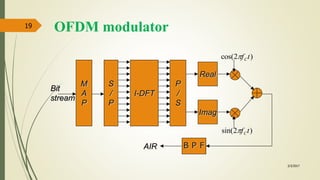
![IMPLEMENTATION
Discrete Fourier transform (DFT) and inverse DFT (IDFT) processes are useful for implementing
these orthogonal signals.
Note that DFT and IDFT can be implemented efficiently by using fast Fourier transform (FFT)
and inverse fast Fourier transform (IFFT), respectively.
In the OFDM transmission system, N-point IFFT is taken for the transmitted symbols
so as to generate , the samples for the sum of N orthogonal subcarrier signals.
Let y[n] denote the received sample that corresponds to x[n] with the additive noise w[n] (i.e.,
y[n] =x[n]+w[n]).
Taking the N-point FFT of the received samples, , the noisy version of transmitted
symbols
can be obtained in the receiver.](https://image.slidesharecdn.com/ofdm-170303183334/85/orthogonal-frequency-division-multiplexing-OFDM-9-320.jpg)
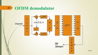
![OFDM demodulation
3/3/2017
21
)(
2
1
)2sin()2cos(
2
1
)]2cos()([
)(2sin)(2cos)(
1
0
00
1
0
00
tstnfbtnfatftsLPF
tnffbtnffats
I
N
n
nnC
N
n
cncn
)(
2
1
)2cos()2sin(
2
1
])2sin()([
1
0
00 tstnfbtnfatftsLPF Q
N
n
nnC
u t s t js t d eI Q n
j nf t
n
N
( ) ( ) ( )
2
0
1
0
dn = FFT(u(k))](https://image.slidesharecdn.com/ofdm-170303183334/85/orthogonal-frequency-division-multiplexing-OFDM-21-320.jpg)

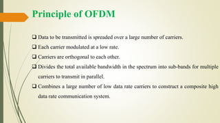
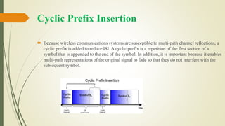
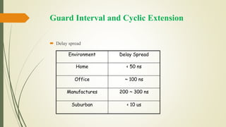
The document discusses Orthogonal Frequency Division Multiplexing (OFDM), its principles, and applications in technologies such as ADSL and digital broadcasting. It explains the process of spreading transmitted data over multiple orthogonal carriers, the necessity of cyclic prefix insertion to mitigate interference, and the application of Fast Fourier Transform (FFT) for signal processing. Details are provided on the implementation of OFDM systems, including challenges related to intersymbol and inter-carrier interference.