Download as PDF, PPTX
![Background
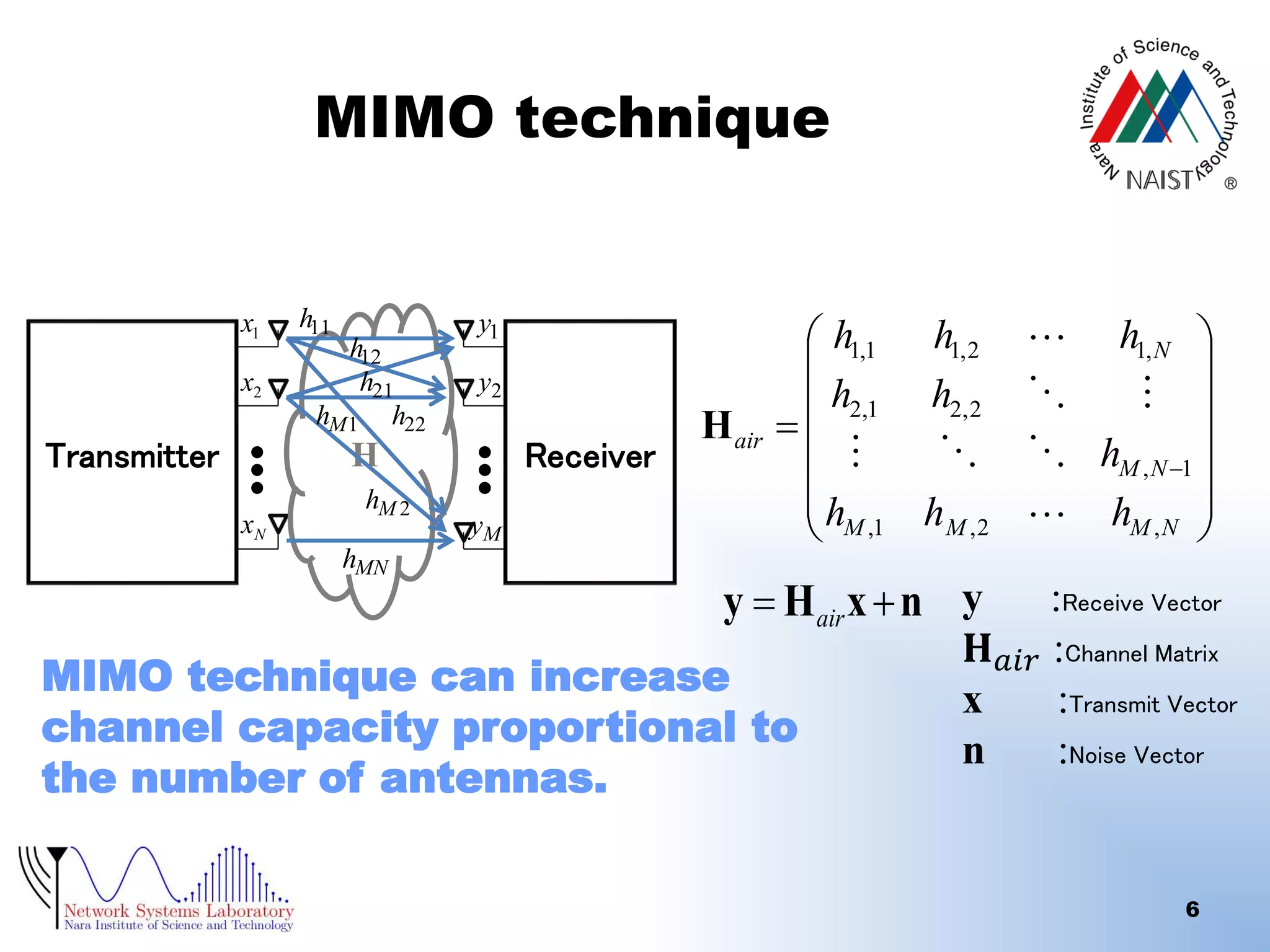
Requirements of Next Generation Network
Source2
Source1
High speed and
large capacity
wireless access
Adaptive
control of base
station
Accommodations
of various
communication
standards
(Heterogeneous)
Source1:Cisco VNI Mobile, 2011
Source2:ZTE ZTE technology N0.1, 2011
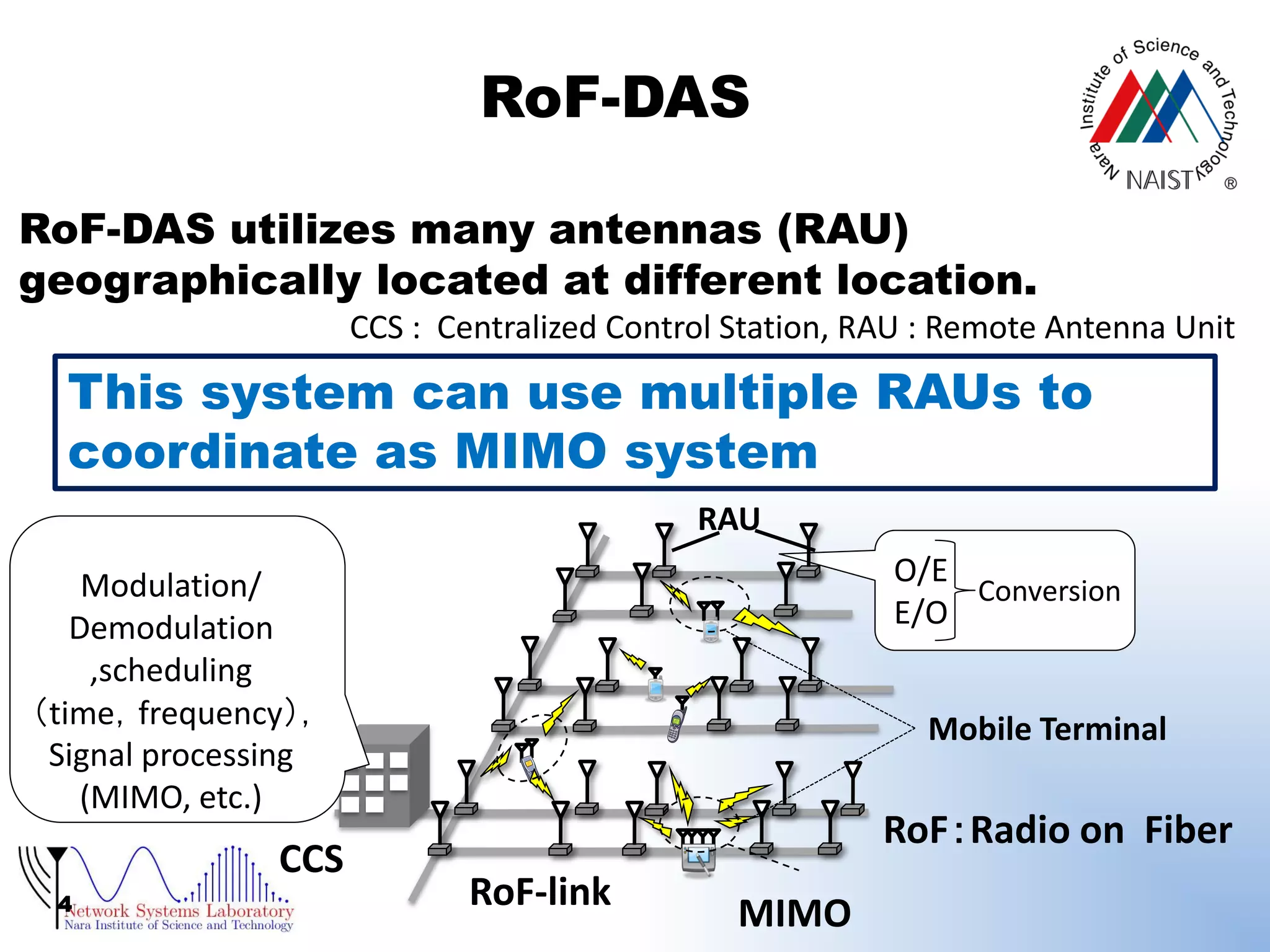
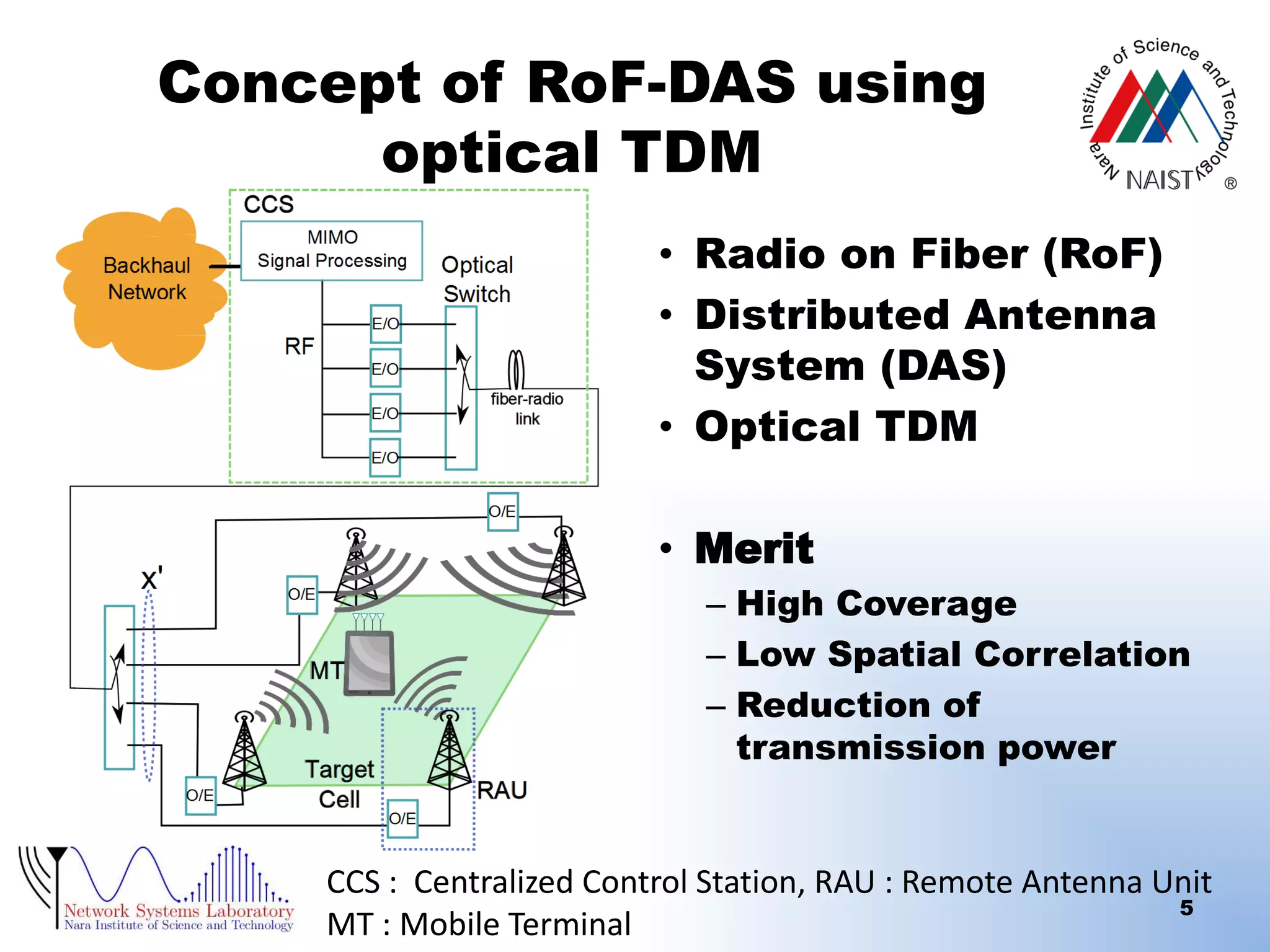
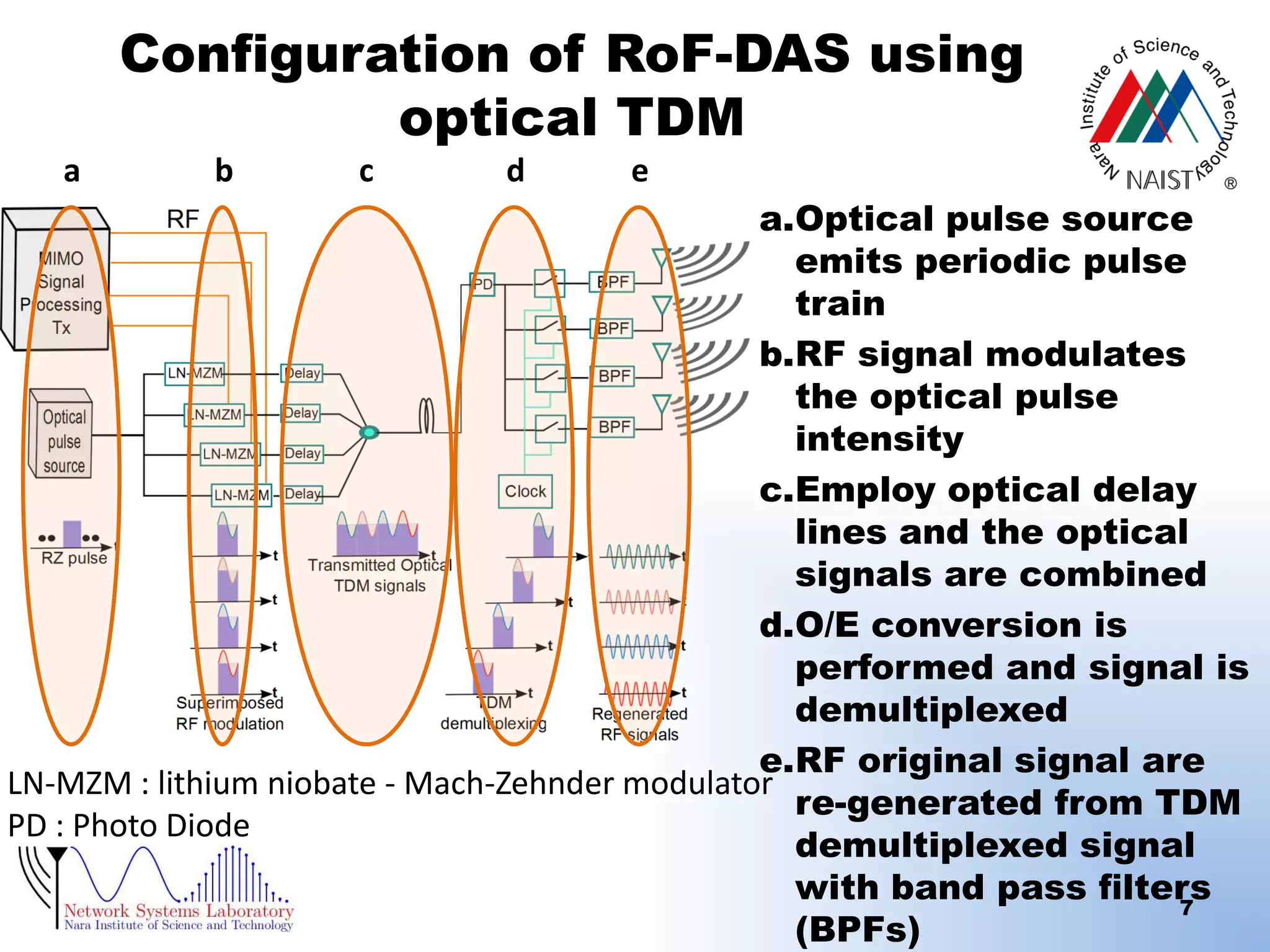
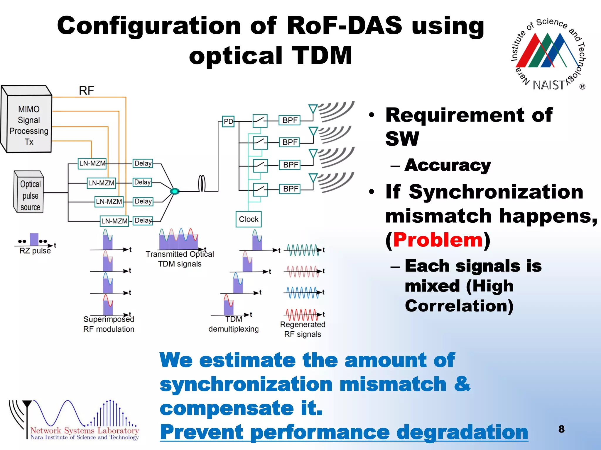
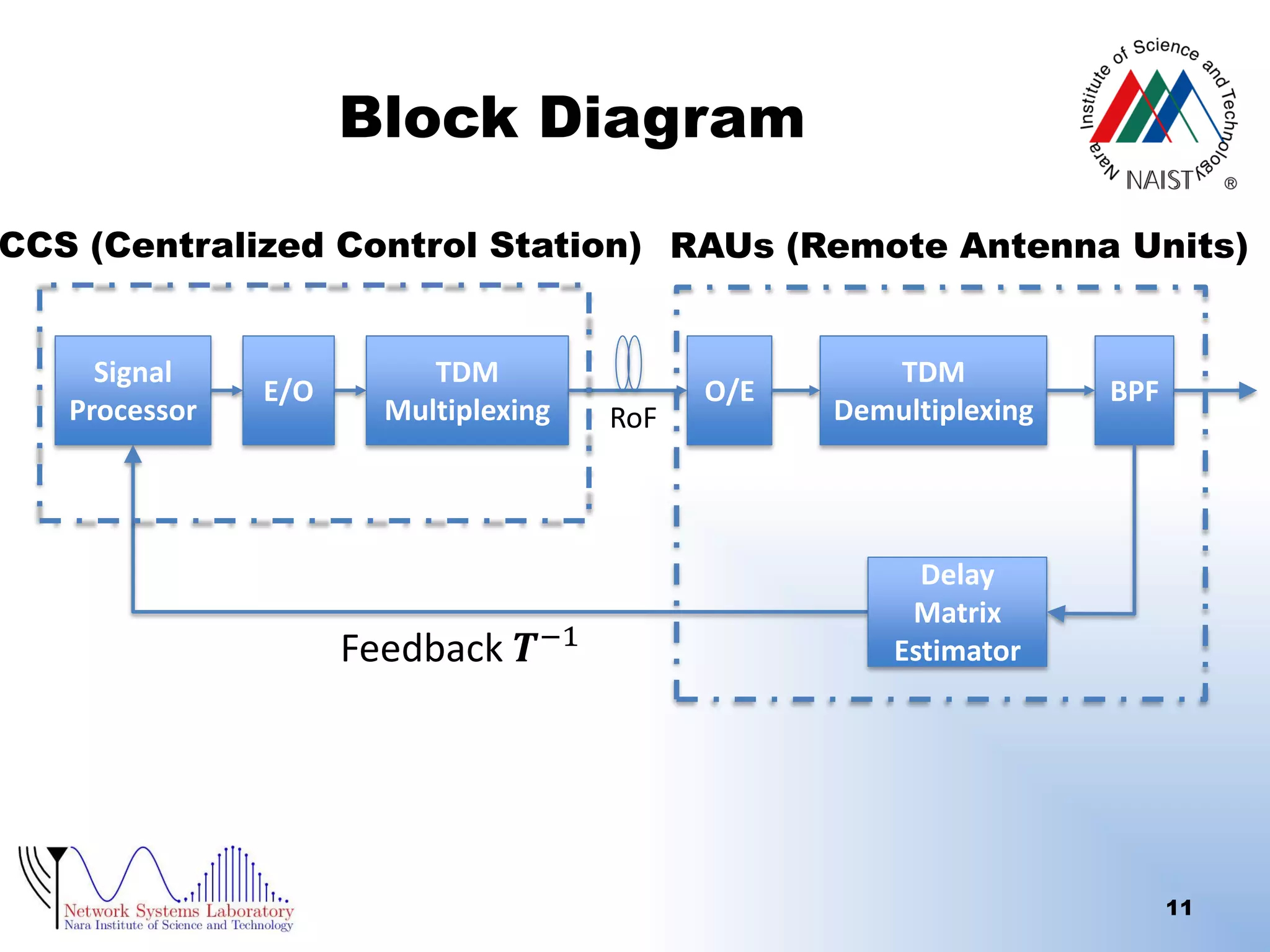
RoF-DAS using optical TDM (Time Division
Multiplexing)
[Radio on Fiber (RoF),Distributed Antenna System (DAS)]
3](https://image.slidesharecdn.com/naisttransportationofmimoradiosignals-131101110802-phpapp02/75/Transportation-of-MIMO-Radio-Signals-over-RoF-Distributed-Antenna-System-and-its-Performance-Analysis-in-the-Presence-of-Incomplete-Synchronization-in-Optical-TDM-3-2048.jpg)
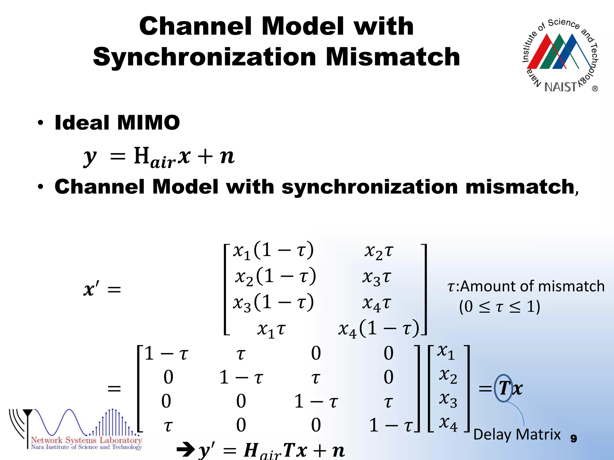
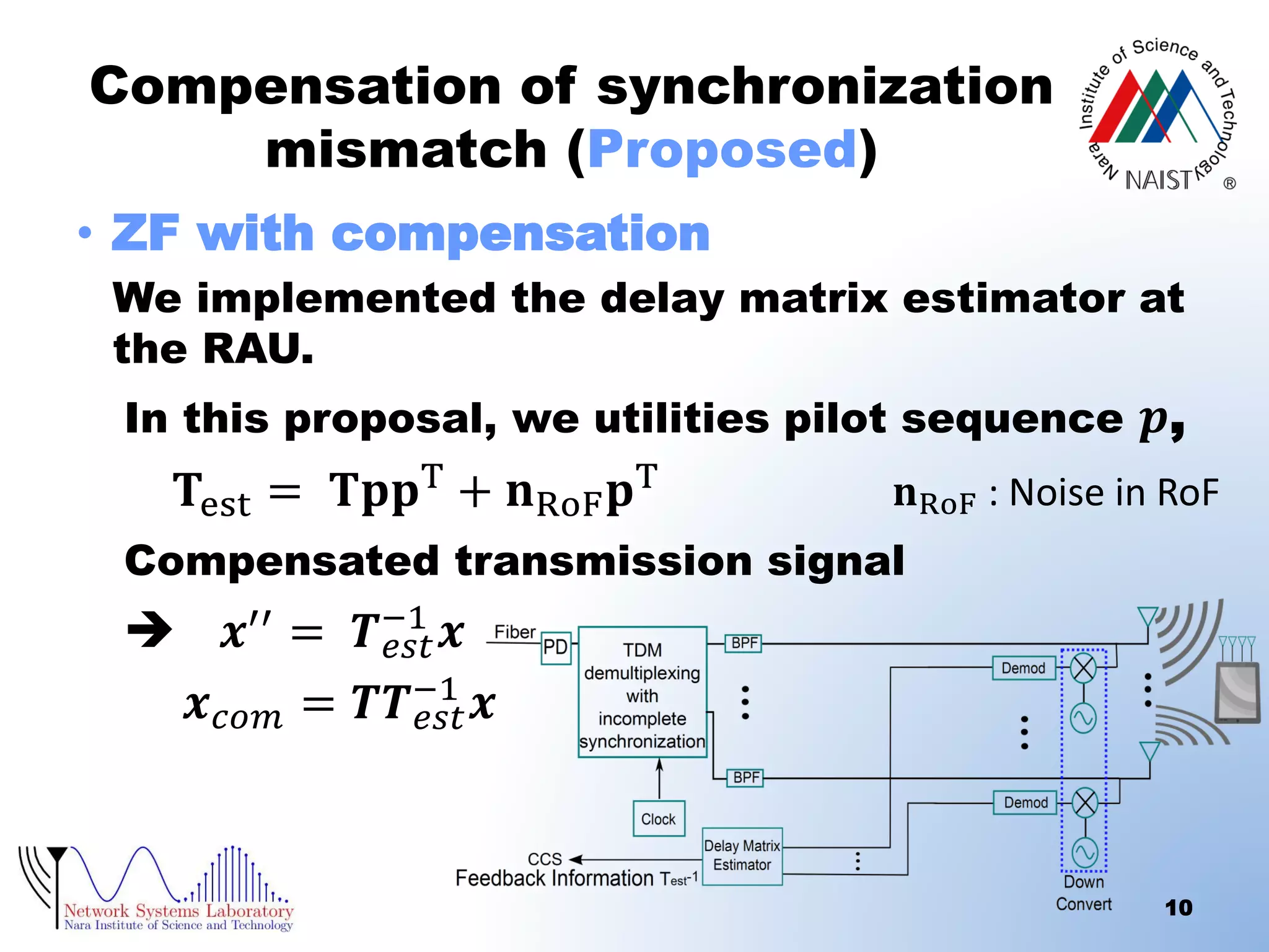
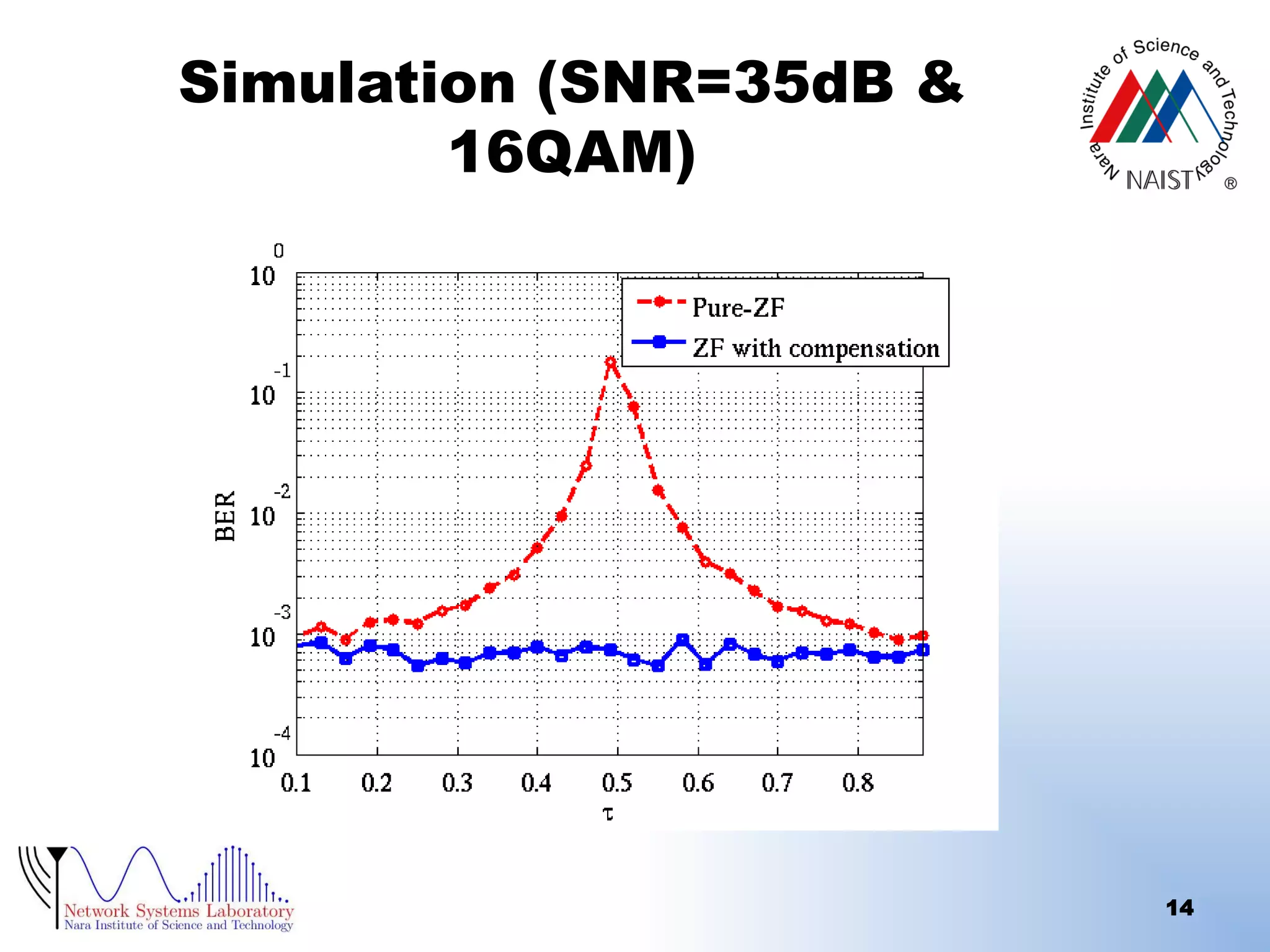
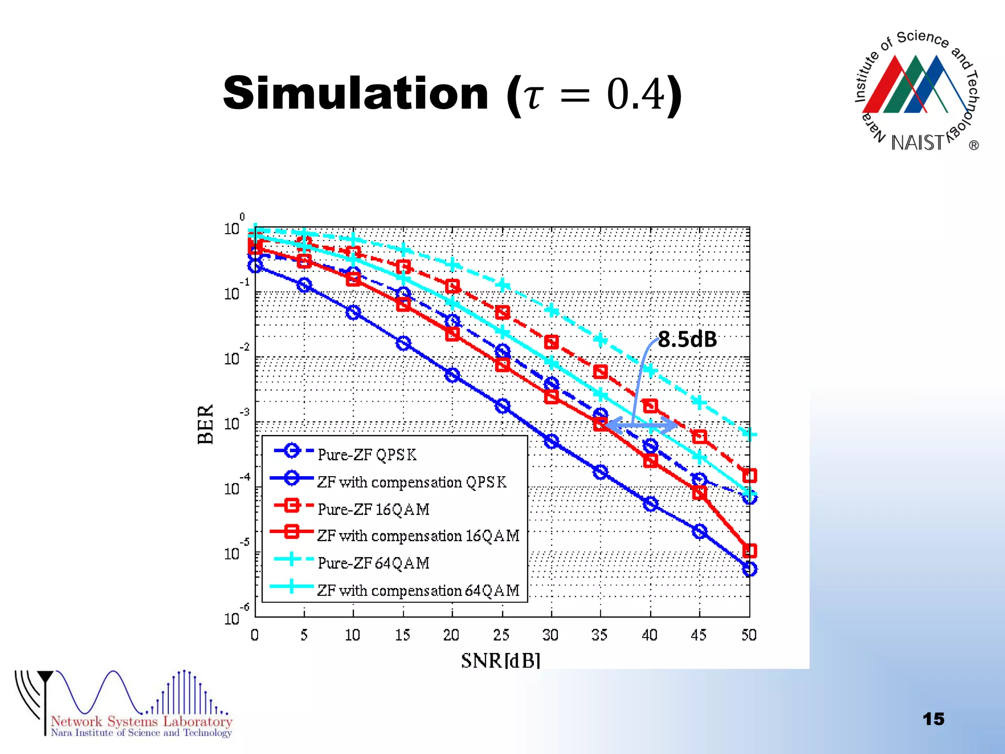

The document presents a performance analysis of a radio on fiber-distributed antenna system (ROF-DAS) with a focus on addressing incomplete synchronization issues in optical time division multiplexing (TDM). It introduces a compensation scheme to mitigate degradation caused by synchronization mismatch, which enhances bit error rate (BER) performance. Future work is suggested to explore optical OFDM applications and to address nonlinear distortion in ROF characteristics.


![2014.03.31.bach glc-pham-finalizing[conflict]](https://cdn.slidesharecdn.com/ss_thumbnails/2014-150417024004-conversion-gate01-thumbnail.jpg?width=640&height=640&fit=bounds)


![Coded Agents – with UiPath SDK + LangGraph [Virtual Hands-on Workshop]](https://cdn.slidesharecdn.com/ss_thumbnails/codedagentsdeck-251215155422-5497c599-thumbnail.jpg?width=640&height=640&fit=bounds)