Downloaded 28 times

![9
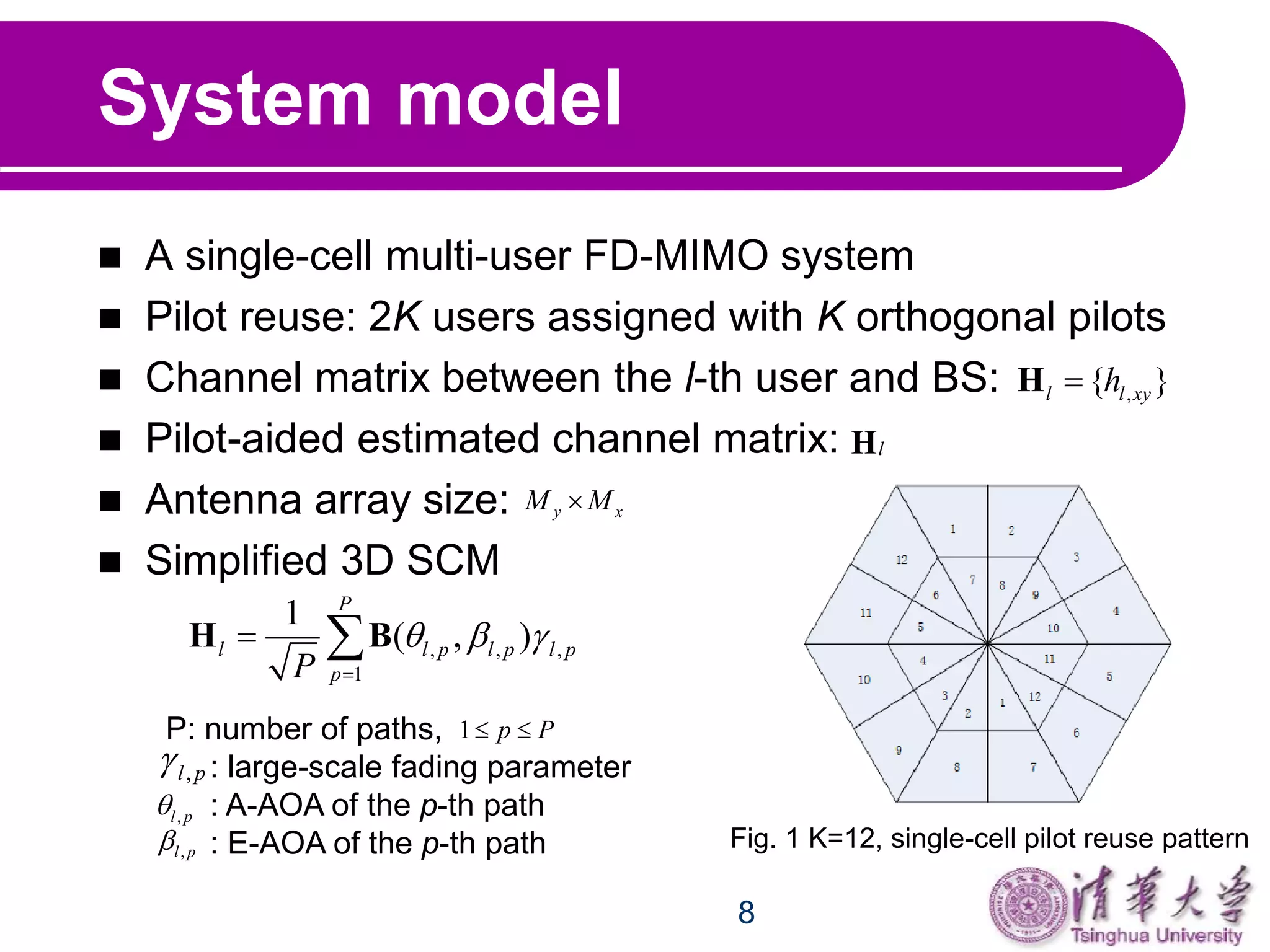
System model
Steering matrix :
Assumption: angular spread of A-AOA is small. E-
AOAs are determined by locations of users.
Inner part user:
Outer part user:
( , ) { }xyb B
cos cos sin
, ( , )
jkD x y
x yb e
0, 1, 0, 1x yx M y M
D: antenna spacing, , is the wavelength2 /k
, min max[ , ]l l
l p
min max m
arctan ,arctan , arctan ,arctanin out
mid id
L L L L
r r r r
min m[ , ]in idd r r
m max[ , ]out idd r r](https://image.slidesharecdn.com/1f0ae273-8e23-4e39-8755-c4dcb5d4f5b4-150907055508-lva1-app6891/75/VTC-location-based-channel-estimation-for-massive-full-dimensional-MIMO-systems-9-2048.jpg)

![11
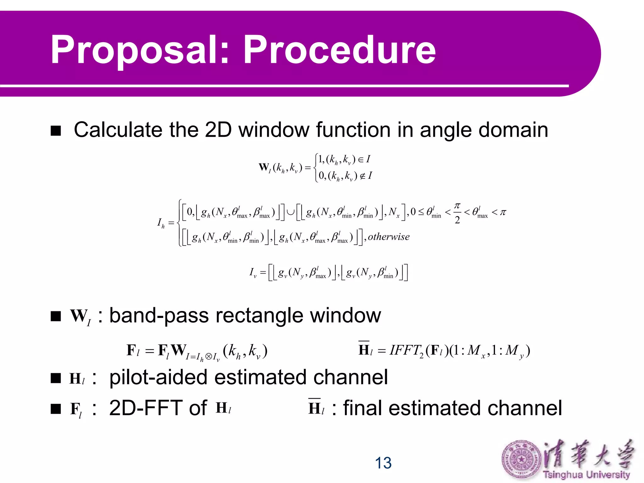
Proposal: 2D-DFT Analysis
Horizontal domain:
can be seen as a single-frequency signal with
Vertical domain:
: single-frequency signal with
2D-DFT of tends to a 2D- function with infinity
number of antennas. Different users have different
impulse position and could be distinguished in angle
domain.
1 2[ , , , ]y
h h h
M B b b b
cos cos
sin
cos cos
1
y
jkD
h jkDy
y
jkDM
e
e
e
b
h
yb cos cosh
D
f
sincos cos sin
1 yjkDMv jkDx jkD
x e e e
b
v
xb sinv
D
f
B ](https://image.slidesharecdn.com/1f0ae273-8e23-4e39-8755-c4dcb5d4f5b4-150907055508-lva1-app6891/75/VTC-location-based-channel-estimation-for-massive-full-dimensional-MIMO-systems-11-2048.jpg)
![12
Proposal: 2D-DFT Analysis
Perform 2D-DFT of :
11
2 ( ) 2 ( )
0 0
11
2 ( ) 2 ( )
0 0
| ( , ) | | || |
| | | |
yx
h h v v
yx
h h v v
MM
j q k j q k
h v
x y
MM
j q k j q k
x y
x y
X k k e e
e e
M M M
Let and( ) cos cosh
x
D k
q k
N
( ) sinv
y
D k
q k
N
( , ) B
| ( , ) |h vX k k reaches maximum value when and both are integers( )hq k( )vq k
( , , )
( , )
h h x
v v y
k g N
k g N
cos cos , [0, )
2
( , , )
cos cos , [ , ]
2
x x
h x
x
D
N N
g N
D
N
min max( , ) sin , [ , ]v y y y
D
g N N N
Means rounding operation ](https://image.slidesharecdn.com/1f0ae273-8e23-4e39-8755-c4dcb5d4f5b4-150907055508-lva1-app6891/75/VTC-location-based-channel-estimation-for-massive-full-dimensional-MIMO-systems-12-2048.jpg)
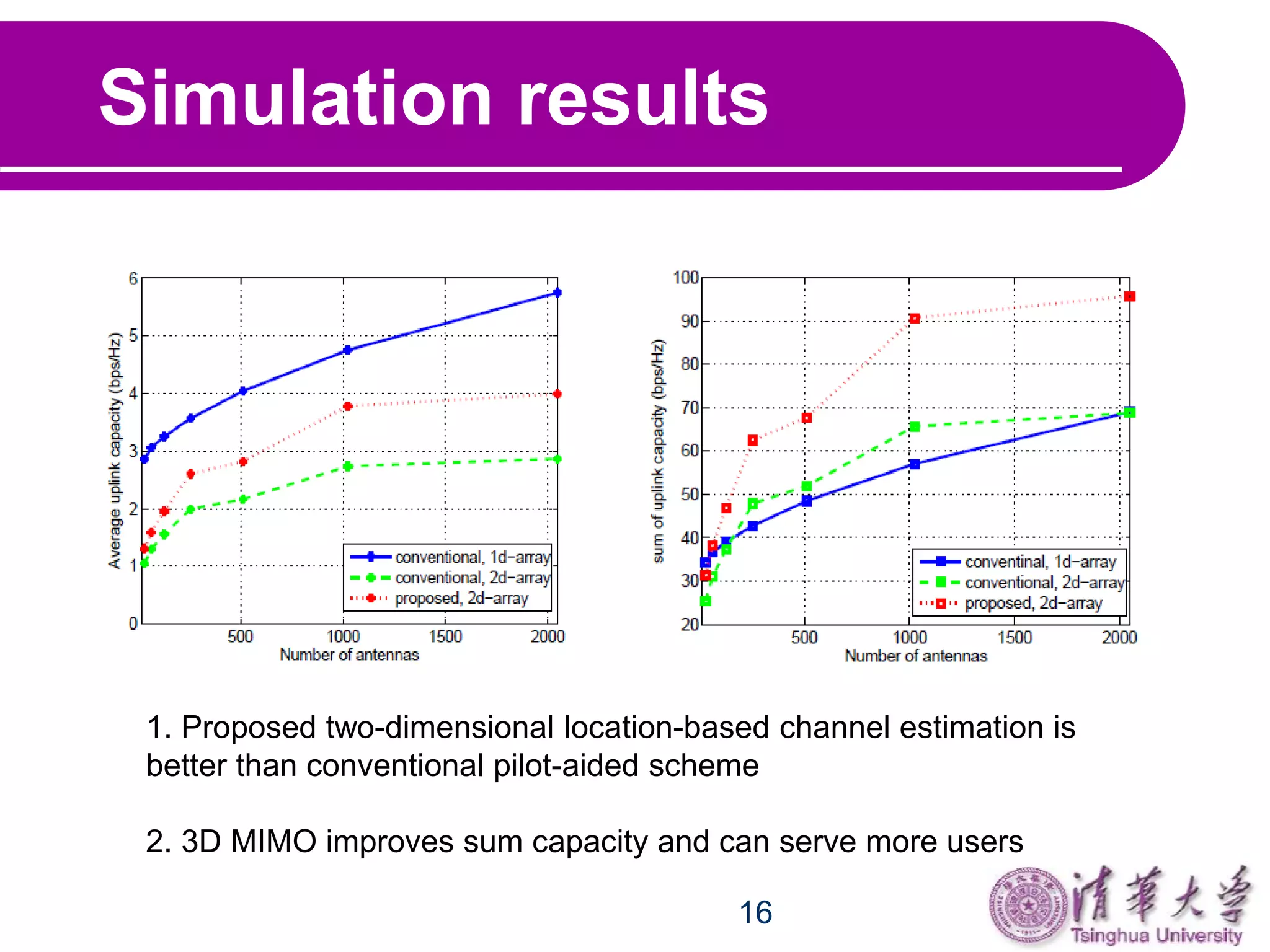


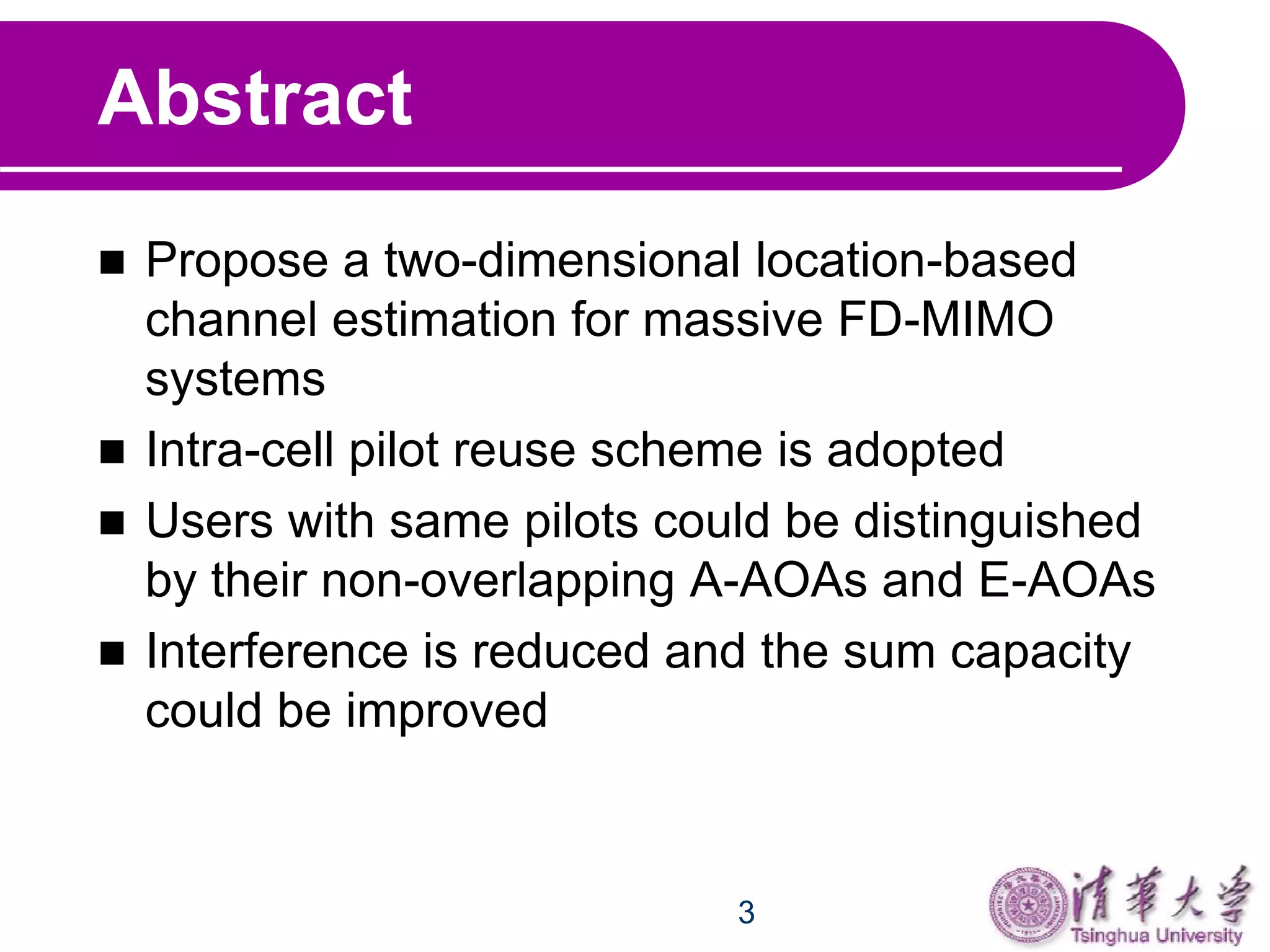
This document proposes a two-dimensional location-based channel estimation method for massive full-dimensional MIMO systems. It uses an intra-cell pilot reuse scheme where users with the same pilots can be distinguished by their unique azimuth and elevation angles of arrival. The method applies a 2D FFT to the pilot-aided channel estimates followed by a 2D window function in the angle domain to isolate the different users. Simulation results show the proposed method outperforms conventional pilot-aided estimation and that 3D MIMO can improve sum capacity and serve more users compared to traditional MIMO systems.


![MU- mimo [autosaved]](https://cdn.slidesharecdn.com/ss_thumbnails/massivemimoautosaved-190612174022-thumbnail.jpg?width=640&height=640&fit=bounds)