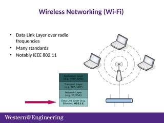
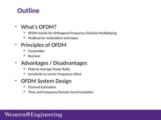
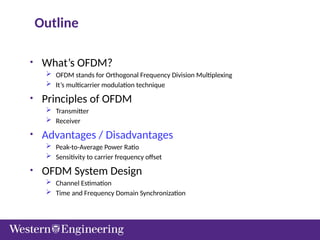
Outline
• What’s OFDM?
OFDM stands for Orthogonal Frequency Division Multiplexing
Multicarrier modulation technique
• Principles of OFDM
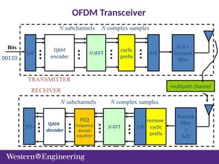
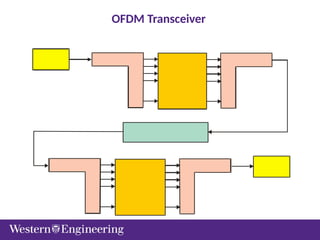
Transmitter
Receiver
• Advantages / Disadvantages
Peak-to-Average Power Ratio
Sensitivity to carrier frequency offset
• OFDM System Design
Channel Estimation
Time and Frequency Domain Synchronization
3.
f
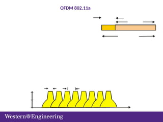
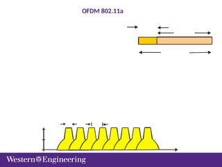
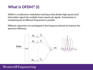
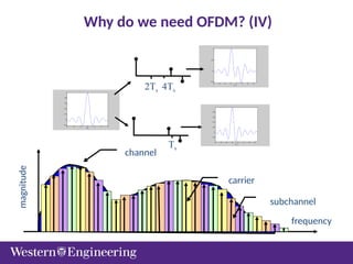
OFDM is amulticarrier modulation technique that divides high-speed serial
information signal into multiple lower-speed sub-signals. Transmission is
simultaneously at different frequencies in parallel.
Different subcarriers are overlapped in the frequency domain to improve the
spectrum efficiency.
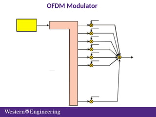
What is OFDM? (I)
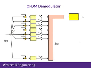
y(n)
f0
f1
fn-1
+
S/P
Data
X0
X1
XN-1
4.
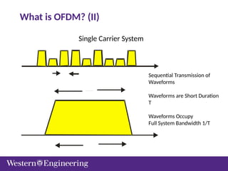
Single Carrier System
SequentialTransmission of
Waveforms
Waveforms are Short Duration
T
Waveforms Occupy
Full System Bandwidth 1/T
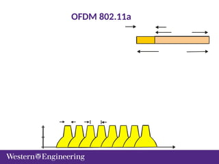
What is OFDM? (II)
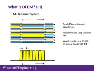
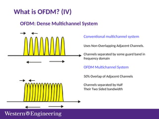
OFDM: Dense MultichannelSystem
Conventional multichannel system
Uses Non-Overlapping Adjacent Channels.
Channels separated by some guard band in
frequency domain
OFDM Multichannel System
50% Overlap of Adjacent Channels
Channels separated by Half
Their Two Sided bandwidth
What is OFDM? (IV)
7.
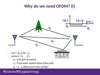
Why do weneed OFDM? (I)
• hc(t) = åk ak d(t - tk)
where k = 0, …, K-1
ak : path gain (complex)
t0 = 0 normalize relative delay of first path
Dk = tk - t0 difference in time-of-flight
| a0 | | a1 | | a2 |
D1
D2
a0
a1
a2
8.
Why do weneed OFDM? (II)
-6 -4 -2 0 2 4 6
-0.2
0
0.2
0.4
0.6
0.8
1
t/Ts
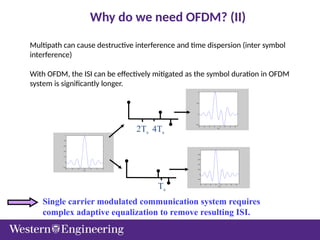
2Ts 4Ts
Ts
-6 -4 -2 0 2 4 6 8
-0.5
0
0.5
1
t/T
s
-6 -4 -2 0 2 4 6 8
-0.2
0
0.2
0.4
0.6
0.8
t/T
s
Single carrier modulated communication system requires
complex adaptive equalization to remove resulting ISI.
Multipath can cause destructive interference and time dispersion (inter symbol
interference)
With OFDM, the ISI can be effectively mitigated as the symbol duration in OFDM
system is significantly longer.
9.
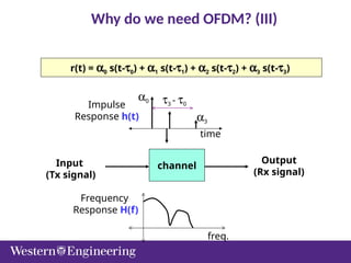
r(t) = a0s(t-t0) + a1 s(t-t1) + a2 s(t-t2) + a3 s(t-t3)
channel
Input
(Tx signal)
Output
(Rx signal)
Impulse
Response h(t)
t3 - t0
time
a3
a0
freq.
Frequency
Response H(f)
Why do we need OFDM? (III)
Outline
• What’s OFDM?
OFDM stands for Orthogonal Frequency Division Multiplexing
It’s multicarrier modulation technique
• Principles of OFDM
Transmitter
Receiver
• Advantages / Disadvantages
Peak-to-Average Power Ratio
Sensitivity to carrier frequency offset
• OFDM System Design
Channel Estimation
Time and Frequency Domain Synchronization
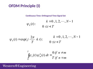
Continuous Time: OrthogonalTime Signal Set
k
0
0 ,1, 2, , 1
( ):
0
0 ,1, 2, , 1
2
( ) exp( ):
0
0
( ) ( )
k
T
n m
k N
t
t T
k N
t j k t
t T
T
if n m
t t dt
T if n m
OFDM Principle (I)
14.
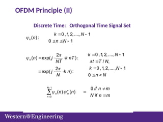
Discrete Time: OrthogonalTime Signal Set
k
1
0
0 ,1, 2,...., 1
( ) :
0 1
0 ,1, 2,...., 1
2
( ) exp( ) :
/ ,
0 ,1, 2,...., 1
2
exp( ) :
0
0
( ) ( )
: ( ) ( ) ( ) ( )
k
N
n m
n
k N k k N k
k N
n
n N
k N
n j k nT
NT t T N
k N
j k n
N n N
if n m
n n
N if n m
NOTE n n n n
OFDM Principle (II)
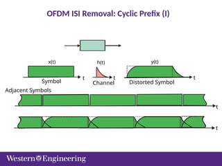
x(t) h(t) y(t)
tt t
t
t
Adjacent Symbols
Symbol Channel Distorted Symbol
OFDM ISI Removal: Cyclic Prefix (I)
17.
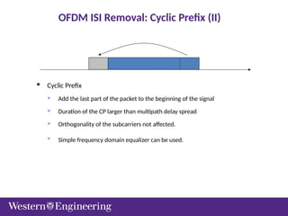
Cyclic Prefix
Add the last part of the packet to the beginning of the signal
Duration of the CP larger than multipath delay spread
Orthogonality of the subcarriers not affected.
Simple frequency domain equalizer can be used.
OFDM ISI Removal: Cyclic Prefix (II)
18.
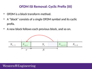
• OFDM isa block transform method.
• A “block” consists of a single OFDM symbol and its cyclic
prefix.
• A new block follows each previous block, and so on.
OFDM ISI Removal: Cyclic Prefix (III)
Cyclic Prefix andOFDM Equalization (I)
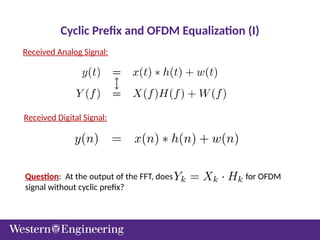
Received Analog Signal:
Received Digital Signal:
Question: At the output of the FFT, does for OFDM
signal without cyclic prefix?
21.
Cyclic Prefix andOFDM Equalization (II)
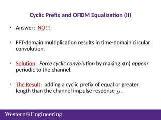
• Answer: NO!!!
• FFT-domain multiplication results in time-domain circular
convolution.
• Solution: Force cyclic convolution by making x(n) appear
periodic to the channel.
• The Result: adding a cyclic prefix of equal or greater
length than the channel impulse response .
22.
Cyclic Prefix andOFDM Equalization (III)
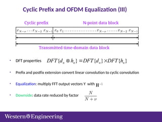
• DFT properties
• Prefix and postfix extension convert linear convolution to cyclic convolution
• Equalization: multiply FFT output vectors Y with .
• Downside: data rate reduced by factor .
}
{
}
{
}
{ n
n
n
n h
DFT
d
DFT
h
d
DFT
Transmitted time-domain data block
Cyclic prefix N-point data block
23.
OFDM In-band Pilots
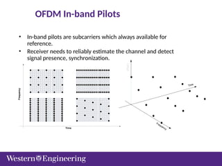
•In-band pilots are subcarriers which always available for
reference.
• Receiver needs to reliably estimate the channel and detect
signal presence, synchronization.
Time
Frequency
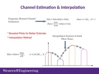
Channel Estimation &Interpolation
1
,...,
1
,
0
),
(
)
(
).
(
)
(
N
k
where
k
N
k
H
k
X
k
Y
)
(
)
(
)
(
)
(
)
(
ˆ k
N
k
H
k
X
k
Y
k
H
N
M
M
k
M
k
N
k
H
k
H ,...,
2
,
,
1
,
)
(
)
(
)
(
ˆ
Frequency Domain Channel
Estimation
Interpolation between in-band
Pilots Tones
• Boosted Pilots for Better Estimate
• Interpolation Method
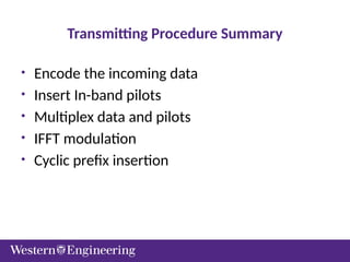
Transmitting Procedure Summary
•Encode the incoming data
• Insert In-band pilots
• Multiplex data and pilots
• IFFT modulation
• Cyclic prefix insertion
29.
Receiver Procedure
• TimingSynchronization
• Removal of Cyclic prefix
• FFT demodulation
• Channel estimation
• Equalization
• Data recovery
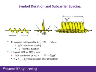
Symbol Duration andSubcarrier Spacing
To maintain orthogonality, let where
= sub-carrier spacing
= symbol duration
If N-point IDFT (or FFT) is used
Total bandwidth (in Hz) =
, symbol duration after CP addition
1
f
T
f
T
f
N
W
CP s
T T T
32.
Outline
• What’s OFDM?
OFDM stands for Orthogonal Frequency Division Multiplexing
It’s multicarrier modulation technique
• Principles of OFDM
Transmitter
Receiver
• Advantages / Disadvantages
Peak-to-Average Power Ratio
Sensitivity to carrier frequency offset
• OFDM System Design
Channel Estimation
Time and Frequency Domain Synchronization
33.
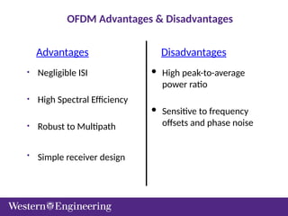
OFDM Advantages &Disadvantages
• Negligible ISI
• High Spectral Efficiency
• Robust to Multipath
• Simple receiver design
High peak-to-average
power ratio
Sensitive to frequency
offsets and phase noise
Advantages Disadvantages
34.
OFDM Advantages
• Lowerequalization complexity compared to single-carrier modulation
due to efficiency of FFT algorithm
• Immune to intersymbol interference caused by multipath channel with
cyclic prefix ( or guard time)
• Higher bandwidth efficiency compared to conventional FDM and single
carrier modulation system
• Spectrum is very flat ( hard for a single-carrier system which requires
very sharp pulse shaping filters)
35.
OFDM Challenges
• Subjectto frequency offset and random phase shift among each
subcarrier
• Very high peak to average power ratio (PAPR)
• Subject to narrow band interference ( OFDM with FEC can
efficiently mitigate this problem)
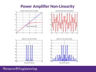
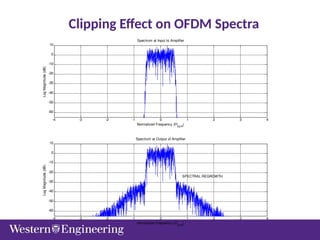
• Sensitive to nonlinear distortion because the spectrum of each
carrier overlapped tightly
36.
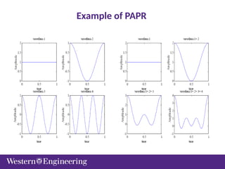
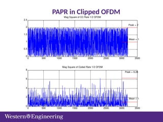
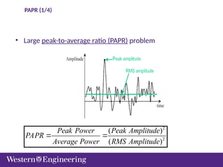
PAPR (1/4)
• Largepeak-to-average ratio (PAPR) problem
2
2
( )
( )
Peak Power Peak Amplitude
PAPR
Average Power RMS Amplitude
37.
PAPR(2/4)
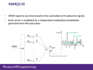
• OFDM signalat any time instant is the summation of N subcarrier signals.
• Each carrier is multiplied by a independent modulated constellation
generated from the input data.
f
S(f)
f1
f2
fn
Foutput
+
S/P
0
Data
d1.m
d2.m
dN.m
38.
PAPR (3/4)
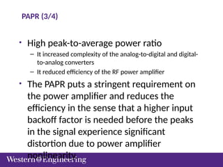
• Highpeak-to-average power ratio
– It increased complexity of the analog-to-digital and digital-
to-analog converters
– It reduced efficiency of the RF power amplifier
• The PAPR puts a stringent requirement on
the power amplifier and reduces the
efficiency in the sense that a higher input
backoff factor is needed before the peaks
in the signal experience significant
distortion due to power amplifier
nonlinearity.
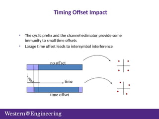
Timing Offset Impact
•The cyclic prefix and the channel estimator provide some
immunity to small time offsets
• Larage time offset leads to intersymbol interference
time
no offset
time offset
46.
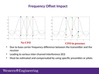
Frequency Offset Impact
•Due to base carrier frequency difference between the transmitter and the
receiver
• Leading to serious inter-channel-interference (ICI)
• Must be estimated and compensated by using specific preambles or pilots
No CFO CFO in presence
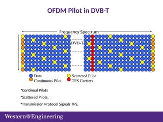
OFDM Pilot inDVB-T
DVB-T
Data
Continuous Pilot
Scattered Pilot
TPS Carriers
Frequency Spectrum
•Continual Pilots
•Scattered Pilots.
•Transmission Protocol Signals TPS.
#46 The effect of a time offset will be different depending on how large the offset is.
If we have large offsets we will get Intersymbol interference, ISI, which will reduce the SNR.
Provided that the cyclic prefix is longer then the channel impulse response we can compensate for the offset in the channel equalizer. The effect of an offset that is in the part of the cyclic prefix not affected by the pervious symbol is only a phase rotation of the signal constellation.
What we want is a system design with high performance and low overhead. What this means is we want the estimates to be in this region, and we want this region to be small.
This can be achieved with an accurate estimator.
#47 Besides CE, CFO is another issue for OFDM.
CFO is caused by base carrier frequency difference between Xmit and Rcvr.
When it presents, it destroys the SC orthogonality, thus leads to serious inter-channel-interference problem, as illustrated in the plots above.
Therefore, CFO must be estimated and compensated.

![PAPR (4/4)
[7]](https://image.slidesharecdn.com/week8ece93082020modulationpartiiofdm-250916140211-ea883715/85/Week8_ECE9308_2020_Modulation_Part_II_OFDM-pptx-39-320.jpg)