Downloaded 110 times
![Communications and Networking20
2 ( )1
0
( )
0 otherwise,
g
B
N
j k t T
sym
k
e t T
p t T
π −⎧
≤ ≤⎪
= ⎨
⎪
⎩
(1)
where Tsym = T + Tg. Note that pk(t) = pk(t+ T) when t is within the guard interval [0,Tg]. It can
be seen from Equation 1 that pk(t) is a rectangular pulse modulated by a sub-carrier with
frequency k · B
N
. The transmitted signal si(t) for the ith OFDM symbol can thus be obtained
by summing over all modulated signals, i.e.,
( )
1
,
0
( ) ,
N
i k i k sym
k
s t X p t iT
−
=
= −∑ (2)
where X0,i,X1,i, ··· ,XN−1,i are complex-valued information-bearing symbols, whose values are
often mapped according to quaternary phase-shift keying (QPSK) or quadrature amplitude
modulation (QAM). Therefore, the transmitted signal s(t) can be considered to be a sequence
of OFDM symbols, i.e.,
( )
1
,
0
( ) ( )
.
i
i
N
k i k sym
i k
s t s t
X p t iT
∞
=−∞
∞ −
=−∞ =
=
= −
∑
∑ ∑
(3)
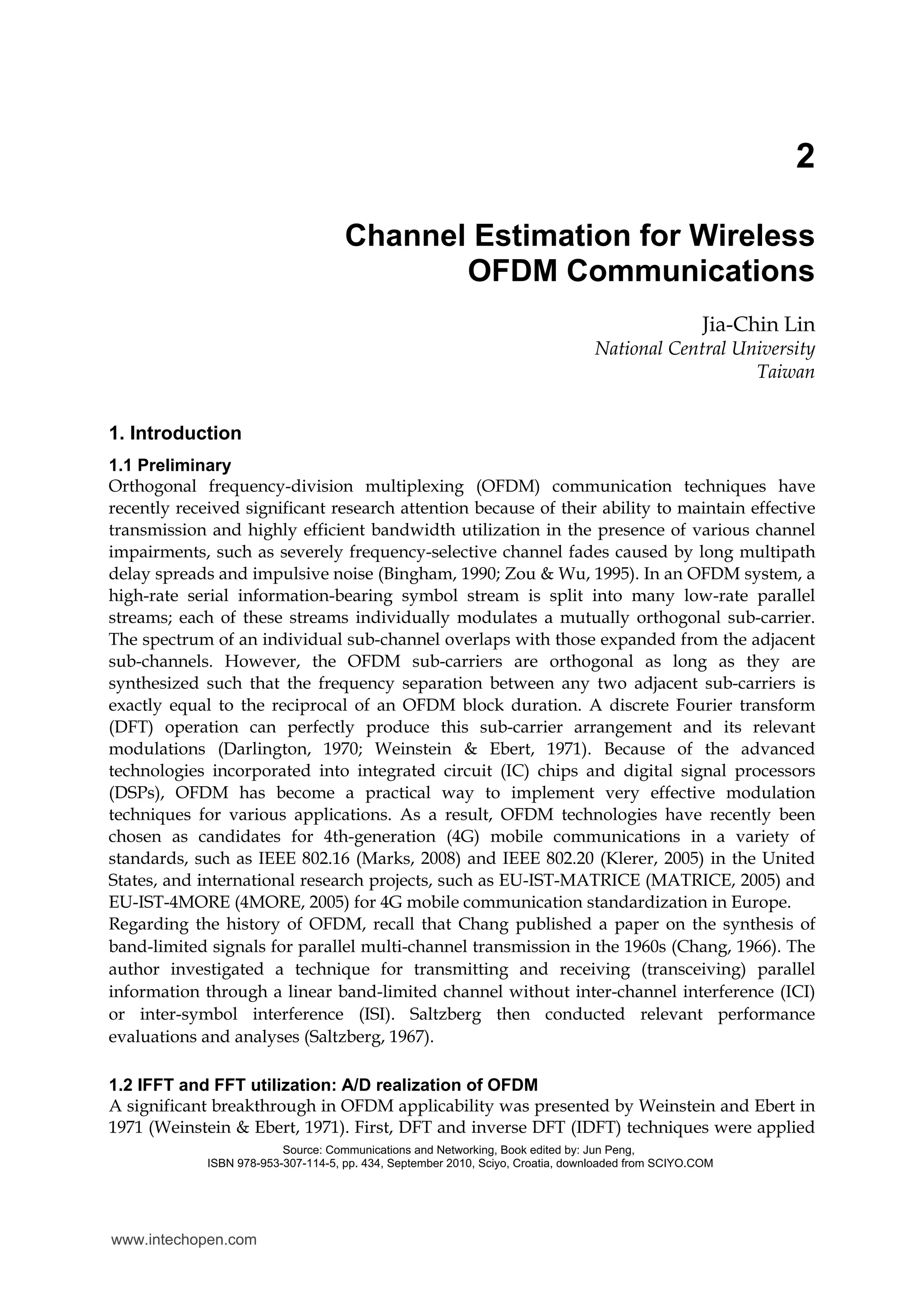
Transmitting Receiving
Filter Bank Filter Bank
Sampler
Multipath Channel
X0,i
X1,i
XN− 1,i
Y0,i
Y1,i
YN− 1,i
p1(t)
p2(t)
pN− 1(t)
q1(t)
q2(t)
qN− 1(t)
s(t)
w(t)
r(t)
Tsym
Tsym
Tsym
h(τ ,t)
Fig. 2. Continuous-time base-band equivalent representation of an OFDM transceiver.
If the length of the CIR h(τ, t) does not exceed the CP length Tg, the received signal r(t) can
be written as
( )
0
( ) ( ) ( )
( , ) ( ) ( ),
gT
r t h s t w t
h t s t d w tτ τ τ
= ∗ +
= − +∫
(4)
where the operator “∗” represents the linear convolution and w(t) is an AWGN.
At the receiving end, a bank of filters is employed to match the last part [Tg,Tsym] of the
transmitted waveforms pk(t) on a subchannel-by-subchannel basis. By taking advantage of
www.intechopen.com](https://image.slidesharecdn.com/channel-estimation-for-wireless-ofdm-communications-141223095009-conversion-gate01/75/Channel-estimation-for-wireless-ofdm-communications-4-2048.jpg)
![Communications and Networking22
where H( f ) denotes the channel transfer function (CTF) and is thus the Fourier transform of
h(τ). The output of the kth receiving MF can therefore be rewritten as
2 ( ) /1
0
1
0
( ) ( ) ( )
( ) ( ) ,
sym symg
g g
sym
g
T Tj l T B NN
k l l k k
l T T
T
N
l l l k k
l T
e
Y X H p d w p d
T
X H p p d W
π ς
ς ς ς ς ς
ς ς ς
−−
∗ ∗
=
−
∗
=
= +
= +
∑ ∫ ∫
∑ ∫
(10)
where
( ) ( ) .
sym
g
T
k kT
W w p dς ς ς∗
= ∫
The transmitting filters pk(t), k = 0,1, ··· ,N − 1 employed here are mutually orthogonal, i.e.,
2 ( ) / 2 ( ) /
( ) ( )
[ ],
sym sym g g
g g
T T j l t T B N j k t T B N
l k
T T
e e
p t p t dt dt
T T
k l
π π
δ
− − −
∗
=
= −
∫ ∫ (11)
where
1
[ ]
0 otherwise
k l
k lδ
=⎧
− = ⎨
⎩
is the Kronecker delta function. Therefore, Equation 10 can be reformulated as
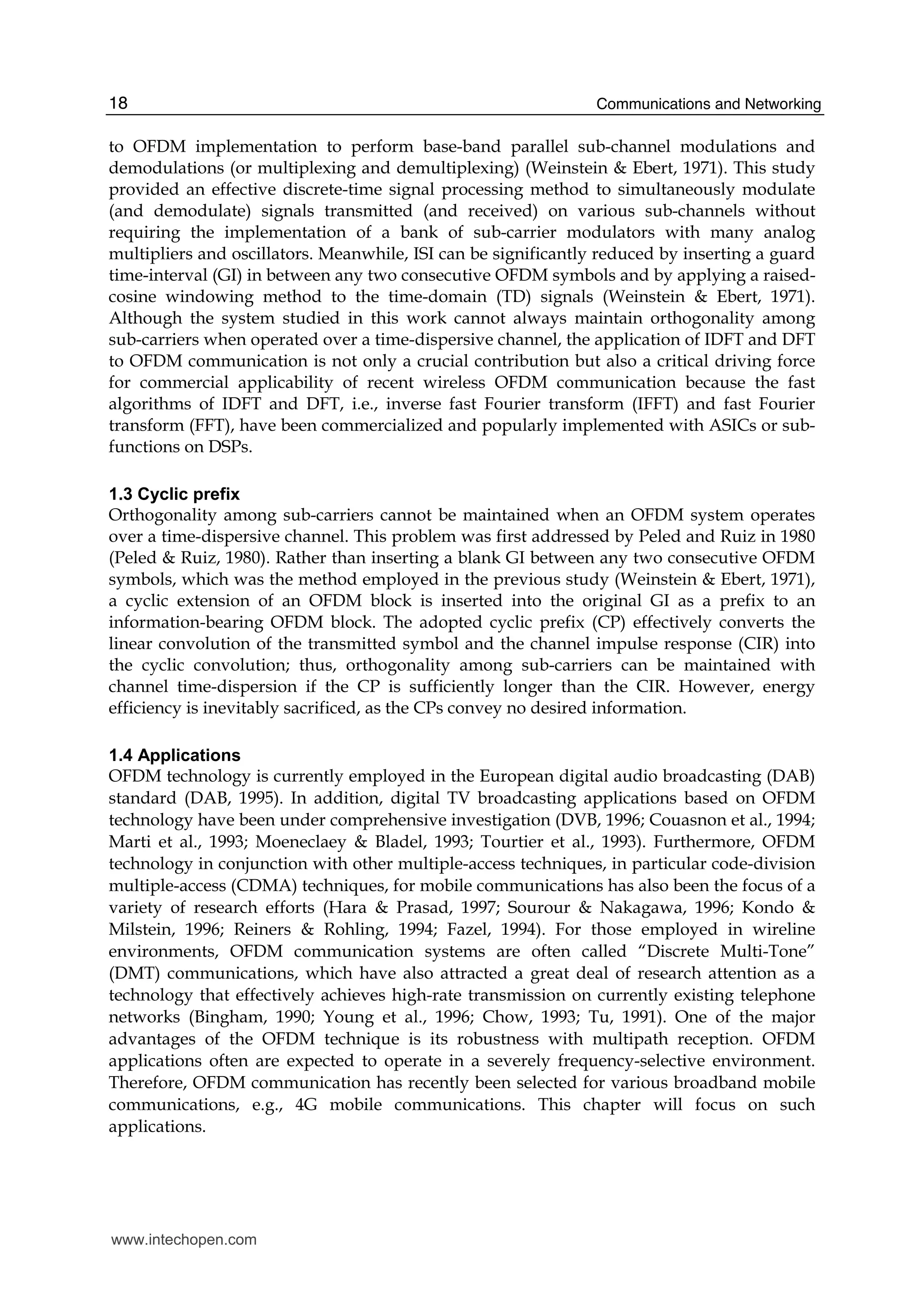
, 0,1, , 1,k k k kY H X W k N= + = −A (12)
where Wk is the AWGN of the kth sub-channel. As a result, the OFDM communication
system can be considered to be a set of parallel frequency-flat (frequency-nonselective)
fading sub-channels with uncorrelated noise, as depicted in Fig. 3.
X0,i
X1,i
XN− 1,i
Y0,i
Y1,i
YN− 1,i
H0,i
H1,i
HN− 1,i
W0,i
W1,i
WN− 1,i
Fig. 3. OFDM communication is converted to transmission over parallel frequency-flat
sub-channels.
www.intechopen.com](https://image.slidesharecdn.com/channel-estimation-for-wireless-ofdm-communications-141223095009-conversion-gate01/75/Channel-estimation-for-wireless-ofdm-communications-6-2048.jpg)
![Channel Estimation for Wireless OFDM Communications 23
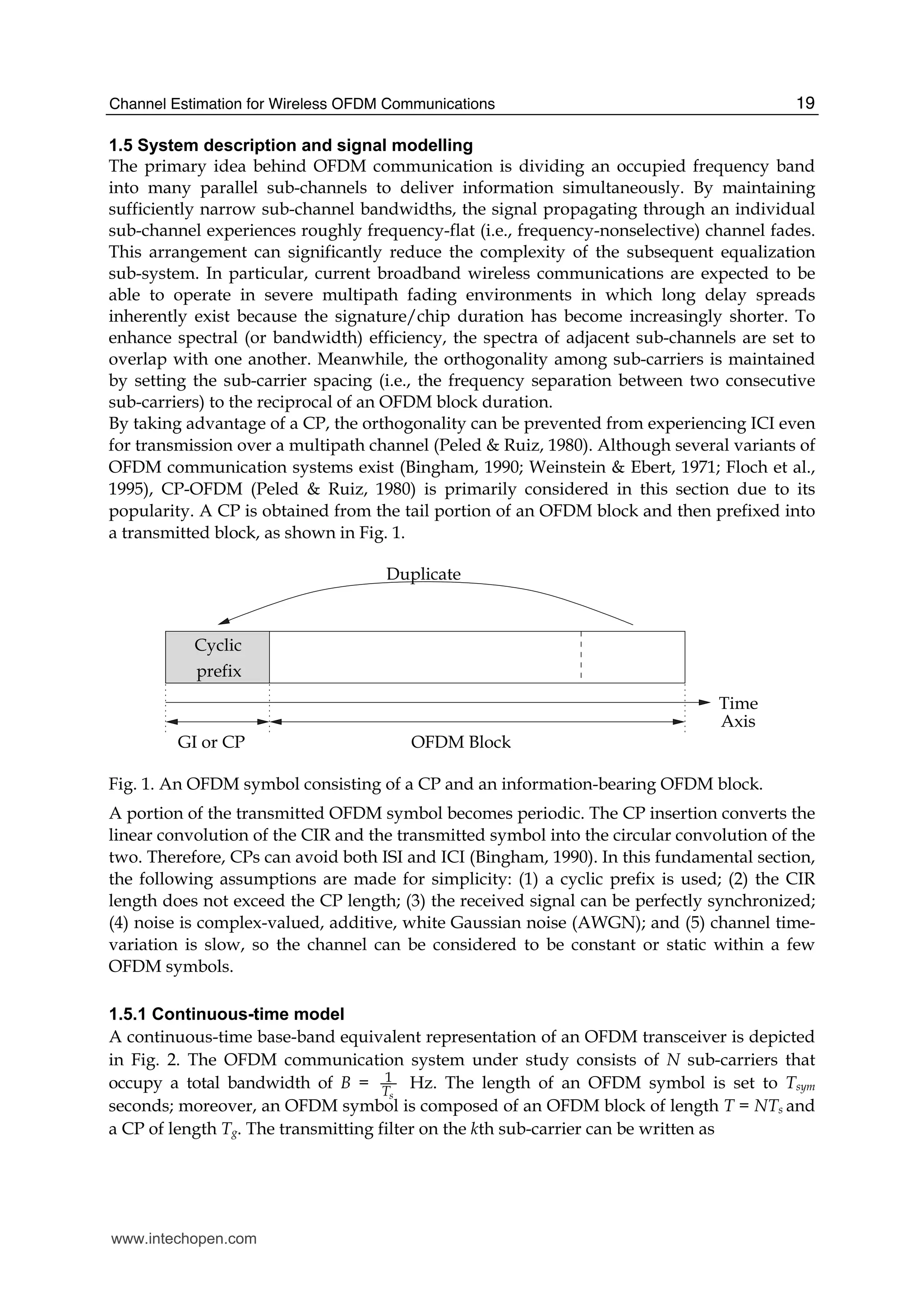
1.5.2 Discrete-time model
A fully discrete-time representation of the OFDM communication system studied here is
depicted in Fig. 4. The modulation and demodulation operations in the continuous-time
model have been replaced by IDFT and DFT operations, respectively, and the channel has
been replaced by a discrete-time channel.
X0,i
X1,i
XN− 1,i
s[n]
h[m,n]
w[n]
r[n]
Y0,i
Y1,i
YN− 1,i
CyclicCyclic
PrefixPrefix
Insertion Removal
IDFT DFTP/S S/P
Fig. 4. Discrete-time representation of a base-band equivalent OFDM communication
system.
If the CP is longer than the CIR, then the linear convolution operation can be converted to a
cyclic convolution. The cyclic convolution is denoted as ‘⊗’ in this chapter. The ith block of
the received signals can be written as
{ }{ }
{ }{ }
DFT IDFT
DFT IDFT ,
i N N i i i
N N i i i
= ⊗ +
= ⊗ +
Y X h w
X h W
(13)
where Yi = [Y0,i Y1,i ··· YN−1,i]T
is an N × 1 vector, and its elements represent N demodulated
symbols; Xi = [X0,i X1,i ··· XN−1,i]T
is an N × 1 vector, and its elements represent N
transmitted information-bearing symbols; hi = [h0,i h1,i ··· hN−1,i]T
is an N × 1 vector, and its
elements represent the CIR padded with sufficient zeros to have N dimensions; and
wi = [w0,i w1,i ··· wN−1,i]T
is an N × 1 vector representing noise. Because the noise is assumed to
be white, Gaussian and circularly symmetric, the noise term
DFT ( )i N i=W w (14)
represents uncorrelated Gaussian noise, and Wk,i and wn,i can be proven to have the same
variance according to the Central Limit Theorem (CLT). Furthermore, if a new operator ”☼”
is defined to be element-by-element multiplication, Equation 13 can be rewritten as
{ }DFT
,
i i N i i
i i i
= +
= +
Y X h W
X H W
Y
Y
(15)
where Hi = DFTN {hi} is the CTF. As a result, the same set of parallel frequency-flat sub-
channels with noise as presented in the continuous-time model can be obtained.
Both the aforementioned continuous-time and discrete-time representations provide insight
and serve the purpose of providing a friendly first step or entrance point for beginning
readers. In my personal opinion, researchers that have more experience in communication
fields may be more comfortable with the continuous-time model because summations,
integrations and convolutions are employed in the modulation, demodulation and (CIR)
www.intechopen.com](https://image.slidesharecdn.com/channel-estimation-for-wireless-ofdm-communications-141223095009-conversion-gate01/75/Channel-estimation-for-wireless-ofdm-communications-7-2048.jpg)
![Communications and Networking28
cannot function in the mobile environment because of rapid channel variation and real-time
requirements. In fact, it is difficult to design an effective moving-average filter (or an
integrate-and-dump (I/D) filter) for the previous studies (Muck et al., 2006; 2005; 2003; Ma
et al., 2006) because the moving-average filter must have a sufficiently short time-averaging
duration (i.e., sufficiently short I/D filter impulse response) to accommodate both the time-
variant behaviors of channel tap-weighting coefficients and to keep the a priori statistics of
the PRP unchanged for effective CE and must also have a sufficiently long time-averaging
duration (i.e., sufficiently long I/D filter impulse response) to effectively suppress various
kinds of interference and reduce AWGN.
A previous work (Ohno & Giannakis, 2002) investigated an optimum training pattern for
generic block transmission over time-frequency selective channels. It has been proven that
the TD training sequences must be placed with equal spacing to minimize mean-square
errors. However, the work (Ohno & Giannakis, 2002) was still in the context of WLAN and
broadcasting applications, and no symbol recovery method was studied. As shown in
Section 6, the self-interference that occurs with symbol recovery and signal detection must
be further eliminated by means of the SIC method.
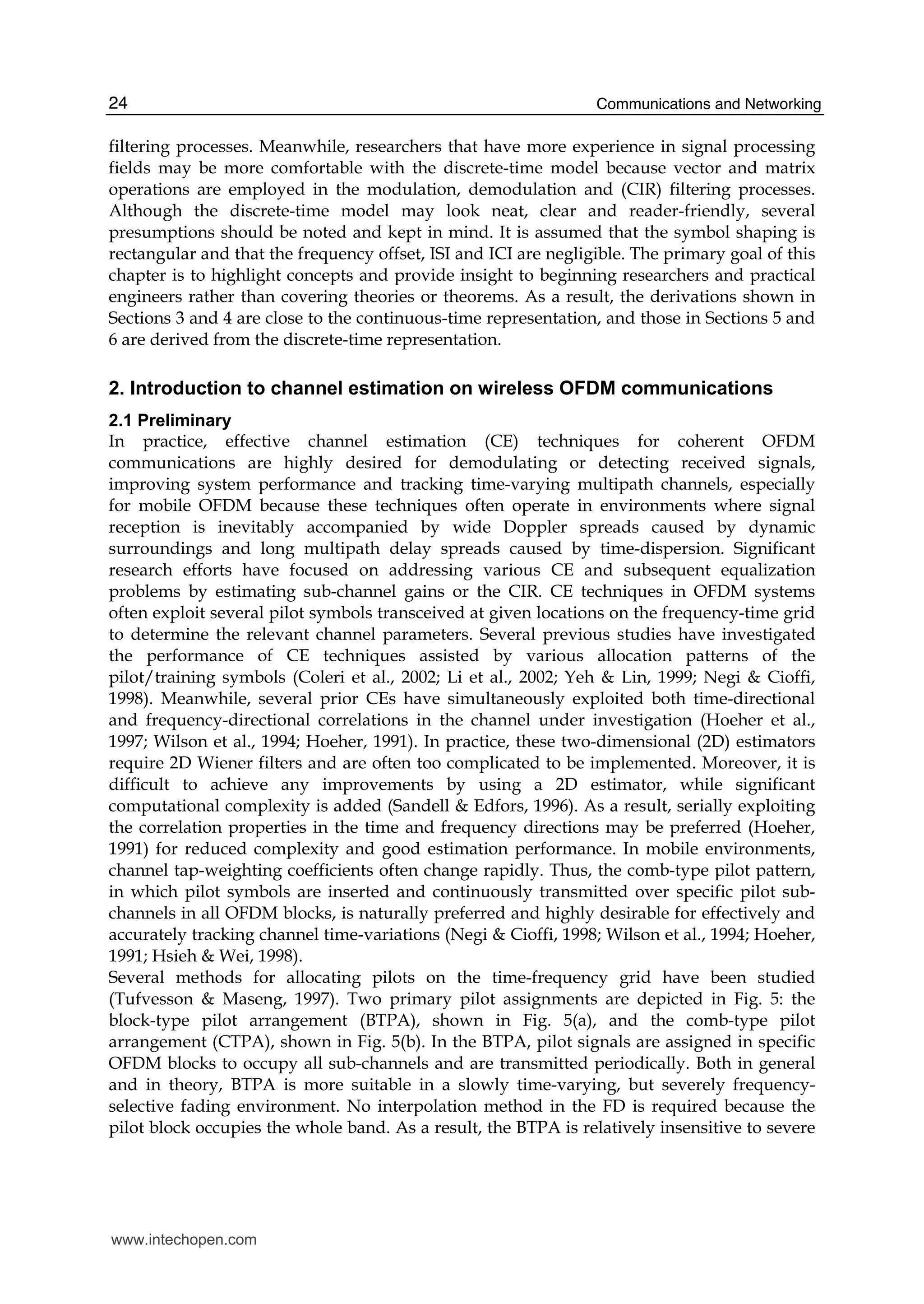
3. Frequency-domain channel estimation based on comb-type pilot
arrangement
3.1 System description
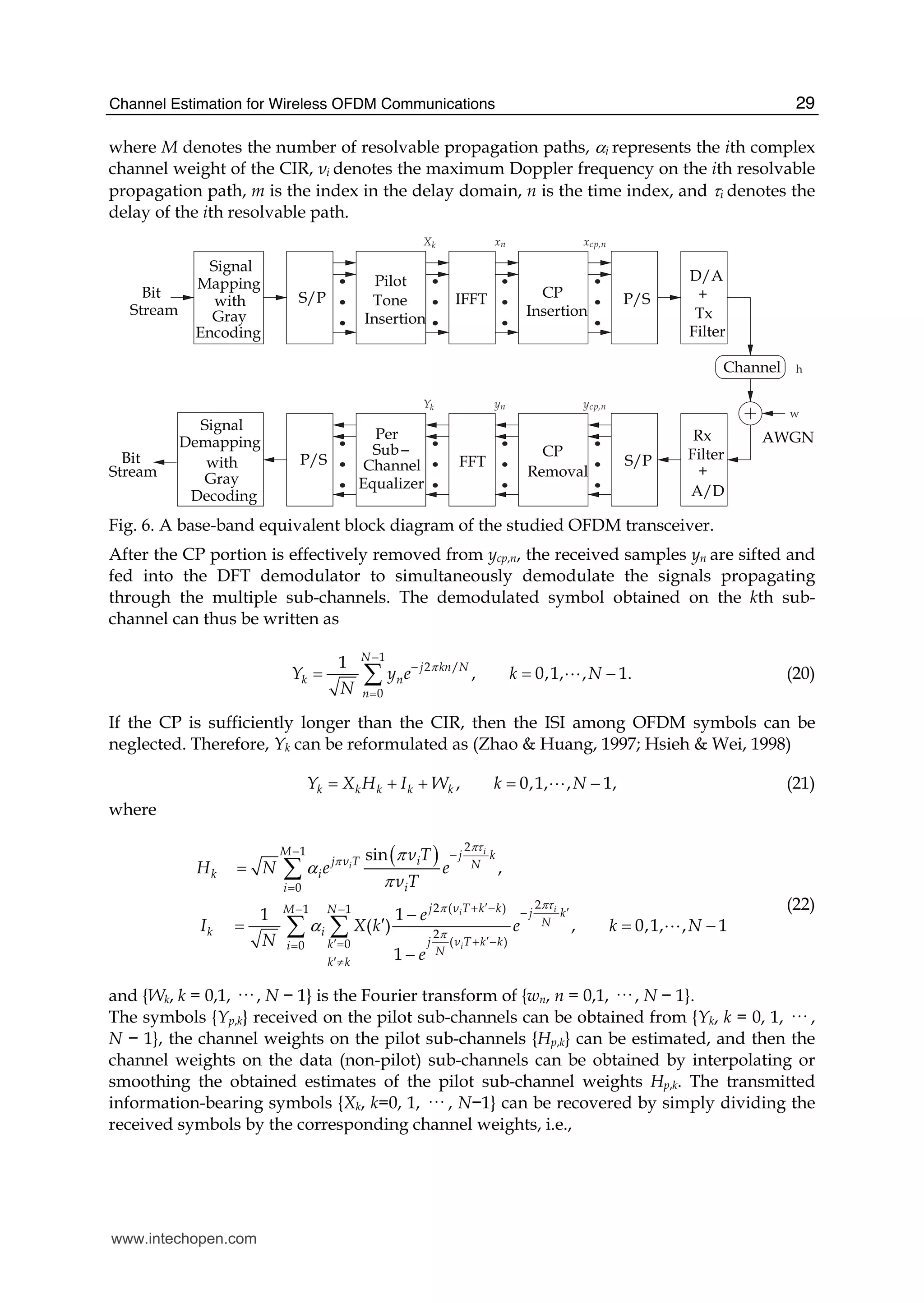
The block diagram of the OFDM transceiver under study is depicted in Fig. 6. Information-
bearing bits are grouped and mapped according to Gray encoding to become
multi-amplitude-multi-phase symbols. After pilot symbol insertion, the block of data
{Xk, k = 0, 1, ··· , N −1} is then fed into the IDFT (or IFFT) modulator. Thus, the modulated
symbols {xn, n = 0, 1, ··· , N − 1} can be expressed as
1
2 /
0
1
, 0,1, , 1,
N
j kn N
n k
k
x X e n N
N
π
−
=
= = −∑ A (16)
where N is the number of sub-channels. In the above equation, it is assumed that there are
no virtual sub-carriers, which provide guard bands, in the studied OFDM system. A CP is
arranged in front of an OFDM symbol to avoid ISI and ICI, and the resultant symbol
{xcp,n, n = −L,−L+ 1, ··· ,N −1} can thus be expressed as
,
, 1, , 1
0,1, , 1,
N n
cp n
n
x n L L
x
x n N
+ = − − + −⎧
= ⎨
= −⎩
A
A
(17)
where L denotes the number of CP samples. The transmitted signal is then fed into a
multipath fading channel with CIR h[m,n]. The received signal can thus be represented as
[ ] [ ] [ , ] [ ],cp cpy n x n h m n w n= ⊗ + (18)
where w[n] denotes the AWGN. The CIR h[m,n] can be expressed as (Steele, 1999)
1
2
0
[ , ] [ ],i s
M
j ν nT
i s i
i
h m n e mTπ
α δ τ
−
=
= −∑ (19)
www.intechopen.com](https://image.slidesharecdn.com/channel-estimation-for-wireless-ofdm-communications-141223095009-conversion-gate01/75/Channel-estimation-for-wireless-ofdm-communications-12-2048.jpg)
![Channel Estimation for Wireless OFDM Communications 37
If the residual timing error ϑ in the above equation falls within [0, L − M], there is no ISI in
the received signal. In practice, ϑ may be only a few samples long and may be less than M,
and ϑ = 0 represents perfect synchronization. The demodulation process at the receiving end
can be performed by means of a DFT operation, and the received signal vector should thus
be transformed back into the sub-carrier space, i.e.,
1
,N
ϑ ϑ
×
= ⋅ ∈TR F r C (41)
where
( )
,
,
{ } ,
1
exp 2 / , 0,1, , 1; 0,1, , 1.
N N
k n
k n
f
f j kn N n N k N
N
π
′ ×
′
= ∈
= − = − = −
TF C
A A
Moreover, FT is the complex conjugate of FI defined below Equation 37 and denotes the DFT
matrix. Thus, the demodulated signals Rϑ on the sub-channels are obtained by the DFT
operation, as shown in Equation 41. In addition, some specific components of Rϑ represent
the outputs of the transmitted pilot symbols that pass through the corresponding pilot sub-
channels. These entries of Rϑ, i.e., kRϑ
, k ∈ ζp, are exploited to estimate the pilot sub-channel
by FDLS estimation, LMMSE or a complexity-reduced LMMSE via SVD, as shown in the
previous section. After the pilot sub-channel gains have been estimated by FDLS, LMMSE or
SVD, smoothing or interpolation/extrapolation methods are used to filter out the estimates
of the data sub-channel gains from inter-path interference (IPI), ICI and noise. The
previously mentioned pilot sub-channel estimation and data sub-channel
interpolation/extrapolation can often be considered to be an up-sampling process conducted
in the FD and can therefore be performed fully on the sub-channel space studied in Section 3.
As a matter of fact, the studied technique exploits a TD LS (TDLS) method to estimate the
leading channel tap-weighting coefficients in the CIR, performs zero-padding to form an N-
element vector and finally conducts the DFT operation on the resultant vector to effectively
smooth in the FD. The studied technique accomplishes ideal interpolation with the domain
transformation method used previously (Zhao & Huang, 1997). The whole CTF, including
all of the channel gains on the pilot, data and virtual sub-channels over the entire occupied
frequency band, can therefore be estimated simultaneously. The multipath delay spread of
the transmission channel is typically dynamic and cannot be determined a priori at the
receiving end. Therefore, the number of channel tap-weighting coefficients is often assumed
to be less than L to account for the worst ISI-free case. The training sequence x in the time
direction, which is actually IDFT-transformed from the Np in-band pilot symbols, has a
period of approximately N
Q
because the pilot sub-channels are equally spaced by Q sub-
channels. Therefore, the studied technique based on CTPA can effectively estimate at most
the leading N
Q
channel tap-weighting coefficients. Meanwhile, in accordance with the
Karhunen-Loeve (KL) expansion theorem (Stark & Woods, 2001), the training sequence x
can be considered to be a random sequence with Np degrees of freedom. Therefore, the order
of the TDLS technique studied in this section can be conservatively determined to be at most
Np because x can be exploited to sound a channel with an order less than or equal to Np.
Based on the above reasoning, the number of channel tap-weighting coefficients is assumed
to be less than or equal to Np, and the longest excess delay is thus assumed to be less than
NpTs. Therefore, the received signals rϑ can be reformulated as
www.intechopen.com](https://image.slidesharecdn.com/channel-estimation-for-wireless-ofdm-communications-141223095009-conversion-gate01/75/Channel-estimation-for-wireless-ofdm-communications-21-2048.jpg)
![Channel Estimation for Wireless OFDM Communications 39
4.3 Remarks
The TD LS CE technique for OFDM communications has been studied in practical mobile
environments. The studied TDLS technique based on the CTPA can accurately estimate the
CIR and effectively track rapid CIR variations and can therefore achieve low error
probabilities. A generic estimator is also performed sequentially on all OFDM blocks
without assistance from a priori channel information and without increasing the
computational complexity. Furthermore, the studied technique also exhibits better
robustness to residual timing errors that occur in the DFT demodulation.
Whether OFDM communication should employ FD CE or TD CE has become an endless
debate, because FD CE and equalization have attracted significant attention in recent years.
While the LS method is not new, the TD CE may also not be considered novel. Although
authors of some other publications thought that TDLS CE was not important, this must be a
misunderstanding, and this section provides a very practical study. The material studied in
this section has been deeply investigated in a previous study and its references (Lin, 2008c).
This author strongly encourages interested readers, especially practical engineers and
potential researchers, to examine the study and references closely to gain a deeper
understanding of the applicability and practical value of the OFDM TD LS CE.
5. Channel estimation based on block pilot arrangement
5.1 Preliminary
The preceding two sections describe CE techniques based on the CTPA and taking
advantage of either FD estimation or TD estimation methods. A CE technique based on the
BTPA is discussed in this section. SC-FDMA has been chosen in the LTE specifications as a
promising uplink transmission technique because of its low PAPR. Moreover, SC-FDM
systems can be considered to be pre-coded OFDM communication systems, whose
information symbols are pre-coded by the DFT before being fed into a conventional
OFDMA (Myung et al., 2006).
In practice, pilot signals or reference signals for CE in SC-FDMA systems are inserted to
occupy whole sub-channels periodically in the time direction, which can be considered to be
BTPA. In this section, the signal model and system description of a BTPA-based CE
technique is studied. The material discussed in this section can be found, in part, in a
previous study (Huang & Lin, 2010).
5.2 System description
The information-bearing Gray-encoded symbols χu[n], n = 0,1, ··· , Nu − 1 are pre-spread by
an Nu-point DFT to generate the FD symbols Xu[κ], κ = 0,1, ··· , Nu − 1, i.e.,
1
2 /
0
0,1, , 1,1
[ ] [ ] ,
0,1, , 1,
u
u
N
uj n N
u u
nu
N
X n e
u UN
π κ κ
κ χ
−
−
=
= −
=
= −
∑
A
A
(44)
where U denotes the number of the users transmitting information toward the base-station,
u denotes the user index, Nu denotes the sub-channel number which the uth user occupies, n
denotes the time index and κ denotes the sub-carrier index. For a localized chunk
arrangement used in the LTE specification, Xu[κ], κ = 0,1, ··· , Nu − 1 are allocated onto Nu
sub-channels, i.e.,
www.intechopen.com](https://image.slidesharecdn.com/channel-estimation-for-wireless-ofdm-communications-141223095009-conversion-gate01/75/Channel-estimation-for-wireless-ofdm-communications-23-2048.jpg)
![Communications and Networking40
( )
( )
1
0
[ ],
[ ]
0, , 0,1, , 1.
u
u u i
u i
u u
X k N
S k
k N
κ κ κ
κ κ
−
=
⎧
= Γ = +⎪
= ⎨
⎪ ≠ Γ = −⎩
∑
A
(45)
The transmitted signal of the uth user is given by
1
2 /
0
0,1, , 1;1
[ ] [ ] ,
0,1, , 1.
N
j kn N
u u
k
n N
s n S k e
uN U
π
−
=
= −
=
= −
∑
A
A
(46)
The signal received at the base-station can be expressed as
1 1
0 0
[ ] [ , ] [ ] [ ], 0,1, , 1,
U M
u u
u m
r n h m n s n m w n n N
− −
= =
= − + = −∑ ∑ A (47)
where hu[m,n] is the sample-spaced channel impulse response of the mth resolvable path on
the time index n for the uth user, M denotes the total number of resolvable paths on the
frequency-selective fading channel and w[n] is AWGN with zero mean and a variance of
2
.wσ The time-varying multipath fading channel considered here meets the WSSUS
assumption. Therefore, the channel-weighting coefficient hu[m,n] is modelled as a zero-mean
complex Gaussian random variable, with an autocorrelation function that is written as
{ } ( )* 2
0E [ , ] [ , ] [ ] 2 [ ],u u u u sh m n h k l m J ν n l T m kσ π δ= − − (48)
where δ[· ] denotes the Dirac delta function, J0(· ) denotes the zeroth-order Bessel function of
the first kind, νu denotes the maximum Doppler frequency of the uth user and 2
[ ]u mσ
denotes the power of the mth resolvable path on the channel that the uth user experiences.
In addition, it is assumed in the above equation that the channel tap-weighting coefficients
on different resolvable paths are uncorrelated and that the channel tap-weighting
coefficients on an individual resolvable path have the Clarke’s Doppler power spectral
density derived by Jakes (Jakes & Cox, 1994). To simplify the formulation of Equation 47, it
is assumed that timing synchronization is perfect, ISI can be avoided and CP can be
removed. At the receiving end, the FFT demodulation is conducted, and the received TD
signal r[n] is thus transformed into the FD for demultiplexing, i.e.,
1
2 /
0
1
, /2
0
1
[ ] [ ]
[ ] [ ] [ ], 0,1, , 1,
N
j nk N
n
U
u N u
u
R k r n e
N
H k S k W k k N
π
−
−
=
−
=
=
= + = −
∑
∑ A
(49)
where
( )
, /2
1
2 /
0
1
2 /
0
[ ] [ , ], 0,1, , 1,
1
[ , ] [ , ] , ,
1
[ ] [ ] , 0,1, , 1.
u N u
N
j mk N
u u u
m
N
j nk N
n
H k H k n n N
H k n h m n e k
N
W k w n e k N
N
π
π
κ
−
−
=
−
−
=
= −
= ∀ = Γ
= = −
∑
∑
7 A
A
www.intechopen.com](https://image.slidesharecdn.com/channel-estimation-for-wireless-ofdm-communications-141223095009-conversion-gate01/75/Channel-estimation-for-wireless-ofdm-communications-24-2048.jpg)
![Channel Estimation for Wireless OFDM Communications 41
In conventional FD CE, the weighting coefficient on the kth sub-channel , /2[ ]u NH k is
estimated by the FD LS CE, i.e.,
( )
*
FDLS 2
[ ] [ ]ˆ [ ] , ,
[ ]
p
u
p
R k S k
H k k
S k
κ= = Γ (50)
where Sp[k] represents the pilot symbols in the FD, which are known a priori at the receiving
end. In the LTE uplink, Sp[k], ∀k are obtained by transforming a Zadoff-Chu sequence onto
the sub-carrier domain. Several CE techniques have been discussed in greater detail in a
previous study (Huang & Lin, 2010). When the CE conducted by taking advantage of the
pilot block is complete, several interpolation (or extrapolation) methods are conducted in
the time direction to effectively smooth (or predict) the CTF or CIR upon transmission of the
information-bearing symbols.
6. Channel estimation assisted from time-domain redundancy
6.1 Preliminary
To illustrate CE assisted by TD redundancy, a LS CE technique is studied in this section. The
studied technique can apply pseudo-random-postfix orthogonal-frequency-division
multiplexing (PRP-OFDM) communications to mobile applications, which often operate on
a rapidly time-varying frequency-selective fading channel. Because conventional techniques
that exploit a moving-average filter cannot function on a rapid time-varying channel, the
studied technique takes advantage of several self-interference cancellation (SIC) methods to
reduce IPI, ISI and IBI effectively and in a timely manner. The studied technique can thus
overcome frequency selectivity caused by multipath fading and time selectivity caused by
mobility; in particular, OFDM communication is often anticipated to operate in
environments where both wide Doppler spreads and long delay spreads exist. Because
conventional techniques based on MMSE CE usually require a priori channel information or
significant training data, the studied method exploits a generic estimator assisted by LS CE
that can be performed serially, block by block, to reduce computational complexity.
6.2 System description
The ith N × 1 digital input vector XN[i] is first modulated at the transmitting end with an
IDFT operation. Thus, the TD information-bearing signal block can be expressed as
[ ] [ ],H
N N Ni i′ =x F X (51)
where XN[i] contains 2K ≤ N QPSK-mapping information-bearing symbols;
{ } 2 /1
, , 0 , 0 .j Nkl
N N NW W e k N l N
N
π−
= = ≤ < ≤ <F
Immediately after the IDFT modulation process, a postfix vector c’L = [c0 c1 ··· cL−1]T
is
appended to the IDFT modulation output vector x’N[i]. In this section, c’L is sifted from a
partial period of a long pseudo-random sequence, and c’L is phase-updated at every frame
that contains several TD OFDM signal blocks, rather than using a deterministic postfix
vector with a pseudo-random weight as in the conventional PRP-OFDM (Muck et al., 2006;
www.intechopen.com](https://image.slidesharecdn.com/channel-estimation-for-wireless-ofdm-communications-141223095009-conversion-gate01/75/Channel-estimation-for-wireless-ofdm-communications-25-2048.jpg)
![Communications and Networking42
2005; 2003). This change is desirable when considering that previous works did not suggest
long PRP sequences (Muck et al., 2006; 2005; 2003) and that pseudo-random sequences, e.g.,
the m-sequences or Gold sequences, are actually more general in various communication
applications. Therefore, the ith transmitted block, with a length of ,N LΞ = + can be
expressed as
zp[ ] [ ] ,H
Ni iΞ Ξ= +x F X c (52)
where
1
zp
1 1
, ,N NH H
N
L N L
×
Ξ
× × Ξ×
⎡ ⎤ ⎡ ⎤
= =⎢ ⎥ ⎢ ⎥′⎣ ⎦ ⎣ ⎦
I 0
F F c
0 c
IN denotes an N × N identity matrix and 0L×N denotes a zero matrix of the size indicated in
the subscript. The elements of [ ]iΞx are then transmitted sequentially one by one (probably
with transmit filtering or symbol shaping).
The channel studied here is modelled with a tapped-delay line of order v − 1, i.e., the
impulse response of the investigated channel can be written as h = [h0 h1 ··· hv−1]T
. It is
commonly assumed that the length of the postfix (or prefix) L is larger than the length of the
channel impulse response v. Typically, the multipath delay spread of the transmission
channel is dynamic and cannot be determined a priori at the receiving end. Therefore, the
number of channel tap-weighting coefficients is often assumed to be up to L to consider the
worst ISI-free case, i.e., v = L. Thus, the longest excess delay is vTs, where Ts denotes the
sample duration.
At the receiving end, the ith OFDM symbol block can be formulated as
( )IBI, ISI,[ ] [ ] [ ],i i iΞ Ξ Ξ Ξ Ξ= + +r h h x w (53)
where IBI,Ξh is an Ξ×Ξ Toeplitz upper-triangular matrix in which the upper-most row is
represented by
( )0 IBI, 1 2 1row 0 0 ,v vh h hΞ − −= ⎡ ⎤⎣ ⎦h A A
ISI,Ξh is an Ξ×Ξ Toeplitz lower-triangular matrix in which the left-most column is
represented by
( )0 ISI, 0 1 1column 0 0 ;
T
vh h hΞ −= ⎡ ⎤⎣ ⎦h A A
and [ ]iΞw is the ith AWGN vector of elements with variance 2
.wσ
6.2.1 Channel estimation
In this section, the CIR is considered to be time-varying, but not significantly changing
within one or two OFDM blocks. The symbols employed here in the CE can be written as
follows:
: 1
CE, 1
0: 2 ( 1) 1
[ 1]
[ ] ,
[ ]
N
L v
v L v
i
i
i
Ξ Ξ−
+ −
Ξ − + − ×
〈 〉
〈 〉
−⎡ ⎤
= ⎢ ⎥
⎣ ⎦
r
r
r
(54)
www.intechopen.com](https://image.slidesharecdn.com/channel-estimation-for-wireless-ofdm-communications-141223095009-conversion-gate01/75/Channel-estimation-for-wireless-ofdm-communications-26-2048.jpg)
![Channel Estimation for Wireless OFDM Communications 43
where 〈A〉p:q denotes either a column vector with elements arranged as [Ap Ap+1 ··· Aq]T
, sifted
from a column vector A, or a row vector with elements arranged as [Ap Ap+1 ··· Aq], sifted
from a row vector A. In fact, rCE,L+v−1[i] can be reformulated in detail as follows:
CE, 1 o[ ] [ ] [ ] [ ],L v i i i i+ − ′′ ′= + = +r C h w C h w (55)
where w’’[i] is an (L + v − 1) × 1 AWGN vector of elements whose variances are 2
;wσ
( )L o U[ ] [ ] [ ] ,i i i= + +C C C C
Co is an (L + v − 1) × v Toeplitz matrix in which the left-most column is represented by
( )0 o 0 1 1column 0 0 ;
T
Lc c c −= ⎡ ⎤⎣ ⎦C A A
CU[i] is an (L + v − 1) × v upper-triangular Toeplitz matrix in which the upper-most row is
represented by
( )0 U 1: ( 1)row [ ] 0 1][ [ ;N N vi iΞ − − −−〈 〉 ]=C x
CL[i] is an (L + v − 1) × v lower-triangular Toeplitz matrix in which the left-most column is
represented by
( )0 L 1 0: 2column [ ] [[ ] ;T T
L vi i× Ξ −〈 〉 ]=C 0 x
and
L U[ ] [ ] [ ] [ ] .i i i i′ ′′= + +w w C h C h
In the above equation, CL[i]h results in ISI extending from on-time symbols onto the CE.
Meanwhile, CU[i]h leads to IBI extending from preceding symbols onto the CE. In
accordance with the LS philosophy (Stark & Woods, 2001; Kay, 1993), the CE studied here
can thus be formulated as
( )
1
o o o CE, 1
ˆ [ ] [ ],H H
L vi i
−
+ −=0h rC C C (56)
where
( )CE, 1 CE, 1 CE, 1
1
[ ] [ ] [ 1] .
2
L v L v L vi i i+ − + − + −= + +r rr
In fact, the CE performed using CE, 1[ ]L v i+ −r forces the channel estimator ˆ [ ]i0h , derived in
Equation 56, to effectively exploit the first-order statistics to conduct the TD LI as employed
in a previous work (Ma et al., 2006). Because of the LS philosophy, the statistics of w’[i] need
not be completely known prior to performing the CE and (Co
H
Co)−1
Co
H
can be pre-
calculated and pre-stored as a generic LS CE to reduce complexity. Furthermore, by taking
advantage of decision-directed (DD) SIC, estimates of the CIR can be iteratively obtained by
1
1 o o o CE, 1[ ] {( ) } [ ,ˆ ]H H
L vi i−
+ −= Ch C C r# (57)
www.intechopen.com](https://image.slidesharecdn.com/channel-estimation-for-wireless-ofdm-communications-141223095009-conversion-gate01/75/Channel-estimation-for-wireless-ofdm-communications-27-2048.jpg)
![Communications and Networking44
where
( )CE, 1 CE, 1 U 1 CE, 1
1 0 U 1 ( 1) 1
1 ˆ[ ] [ ] [ 1] [ 1] [ 1] , 1;
2
ˆ[0] [0]; [0] [0] (initialization);
ˆ
ˆ ˆ ˆ
L v L v L v
L v
i i i i i i+ − + − + −
+ − ×
= − − − + + ≥
= =
r r C r
h 0
h
h Ch
#
and U
ˆ [ 1]i −C denotes an (L+v−1)× L upper-triangular Toeplitz matrix in which the upper-
most row is 1: ( 1)
ˆ0 [ 1][ ],N N viΞ − − −〈 〉−x which results from the DD symbols. Eventually, the
estimates of sub-channel gains in individual frequency bins can be obtained by performing
the DFT on the zero-padded replicas of either 0
ˆ [ ]ih or 1
ˆ [ ],ih i.e.,
( )
( ) ( ) ( )
[ ] [ ], 0,1.ˆv v N v
k N k
N v v N v N v
i i k
× −
− × − × −
⎡ ⎤
= =⎢ ⎥
⎢ ⎥⎣ ⎦
h
I 0
H F
0 0
(58)
6.2.2 Symbol recovery
For information detection at the receiving end, the ith information symbol within the DFT
window can be obtained as
SD, 0: 1[ ] [ ] ,N Ni iΞ −〈 〉=r r (59)
and thus, its corresponding FD symbol is
SD,0, SD,[ ] [ ].N N Ni i=R F r (60)
OLA: Based on the signal formatting in the PRP-OFDM communication under investigation,
the ICI caused by various excess delays can be taken into account by modifying the signal
symbol for signal detection to be
( )SD,1, SD, ICIc,[ ] [ ] [ ] ,N N N Ni i i= +R F r r (61)
where
: 2
ICIc,
( 1) 1
[ ]
[ ]
N N v
N
N v
i
i
Ξ + −
− + ×
⎡ ⎤
= ⎢ ⎥
⎢ ⎥⎣
〈 〉
⎦
r
r
0
is exploited here for the purpose of ICI compensation. In fact, RSD,1,N[i] in Equation 61 can be
considered to be a complexity-reduced variant modified from the method that was called
the overlap-add (OLA) approach in previous studies (Muquest et al., 2002; Muck et al.,
2003). It has been proven in previous studies (Muquet et al., 2000) that the OLA helps the
ZP-OFDM achieve the same performance as the CP-OFDM because the OLA can reduce ICI
by compensating for IPI and timing errors to maintain the orthogonality among sub-carriers,
as in the CP-OFDM.
OLA with SIC: The conventional OLA mentioned above introduces some self-interference
to the PRP-OFDM. Therefore, the self-interference occurring in the PRP-OFDM signal
detection has to be eliminated. As a result, the signals fed into the detection can be
formulated as
www.intechopen.com](https://image.slidesharecdn.com/channel-estimation-for-wireless-ofdm-communications-141223095009-conversion-gate01/75/Channel-estimation-for-wireless-ofdm-communications-28-2048.jpg)
![Channel Estimation for Wireless OFDM Communications 45
( )SD,2,k, SD, ICIc, prp,
ˆ[ ] [ ] [ ] [ ] , 0,1,N N N N ki i i i k= + − =R F r r r
where
oprp,
ˆˆ [ ] [ 1], 0,1k ki i k= − =hr C
and
o o
( 1)v v− ×
′=C C# #
denotes a matrix containing the most upper-left (v − 1) × v elements of the matrix o′C# , which
is a circulant matrix in which the left-most column is [c0 c1 ··· cL−1]T
.
6.3 Remarks
The LS CE technique has been thoroughly investigated in practical mobile environments. By
taking advantage of SIC mechanisms, the studied technique can efficiently eliminate various
interferences, accurately estimate the CIR, effectively track rapid CIR variations and,
therefore, achieve low error probabilities. The studied technique can also achieve low bit
error floors. The generic estimator assisted by LS CE can be performed sequentially on all
OFDM blocks for complexity reduction without a priori channel information, which is
required by conventional techniques based on MMSE. Several previous studies and their
references regarding this topic are worth noting (Lin, 2009b;a; Lin & Lin, 2009; Lin, 2008b;a).
7. Summary
In this chapter, a variety of CE techniques on OFDM communications were investigated.
This author does not attempt to present this topic in detail nor provide theoretical
derivations and rigorous statistical analysis, though they are thought of as the most crucial
for a journal publication. Insightful and reader-friendly descriptions are presented to attract
readers of any level, including practicing communication engineers and beginning and
professional researchers. All interested readers can easily find noteworthy materials in
much greater detail from previous publications and the references cited in this chapter.
8. References
4MORE (2005). Eu-ist-4more project website, www.ist-4more.org .
Bingham, J. A. C. (1990). Multicarrier modulation for data transmission: an idea whose time
has come, IEEE Communications Magazine Vol. 28(No. 5): 5–14.
Chang, R.W. (1966). Synthesis of band-limited orthogonal signals for multichannel data
transmission, Bell System Technical Journal Vol. 45(No. 12): 1775–1796.
Chow, P. S. (1993). Bandwidth Optimized Digital Transmission Techniques for Spectrally Shaped
Channels with Impulse Noise, Ph. D. Dissertation, Stanford University, CA.
Coleri, S., Ergen, M., Puri, A. & Bahai, A. (2002). Channel estimation techniques based on
pilot arrangement in ofdm systems, IEEE Transactions on Broadcasting Vol. 48(No.
3): 223–229.
www.intechopen.com](https://image.slidesharecdn.com/channel-estimation-for-wireless-ofdm-communications-141223095009-conversion-gate01/75/Channel-estimation-for-wireless-ofdm-communications-29-2048.jpg)
![Communications and Networking46
Couasnon, T. D., Monnier, R. & Rault, J. B. (1994). Ofdm for digital tv broadcasting, Signal
Processing Vol. 39(No. 1-2): 1–32.
DAB (1995). Radio broadcasting systems; digital audio broadcasting (dab) to mobile,
portable and fixed receivers, European Telecommunications Standards ETS 300 401,
ETSI.
Darlington, S. (1970). On digital single-sideband modulators, IEEE Transactions on Circuit
Theory Vol. 17(No. 3): 409–414.
DVB (1996). Digital broadcasting systems for television, sound and data services, European
Telecommunications Standards prETS 300 744.
Edfors, O., Sandell, M., van de Beek, J.-J., Wilson, S. K. & Borjesson, P. O. (1996). Ofdm
channel estimation by singular value decomposition, Proceedings of IEEE 46th
Vehicular Technology Conference, 1996, IEEE Vehicular Technology Society, Atlanta,
GA, pp. 923–927.
Edfors, O., Sandell, M., van de Beek, J.-J., Wilson, S. K. & Borjesson, P. O. (1998). Ofdm
channel estimation by singular value decomposition, IEEE Transactions on
Communications Vol. 46(No. 7): 931–939.
Elliott, D. F. (1988). Handbook of Digital Signal Processing: Engineering Applications, Academic
Press.
Fazel, K. (1994). Performance of convolutionally coded cdma/ofdm in a frequency-time
selective fading channel and its near-far resistance, Proceedings of IEEE International
Conference on Communications, 1994. ICC’94, IEEE Communications Society, New
Orleans, LA, pp. 1438 – 1442.
Floch, B. L., Alard, M. & Berrou, C. (1995). Coded orthogonal frequency division multiplex
[tv broadcasting], Proceedings of the IEEE Vol. 86(No. 6): 982–996.
Gui, L., Li, Q., Liu, B., Zhang, W. & Zheng, C. (2009). Low complexity channel estimation
method for tds-ofdm based chinese dttb system, IEEE Transactions Consumer
Electronics Vol. 55(No. 3): 1135–1140.
Han, K.-Y., Lee, S.-W., Lim, J.-S. & Sung, K.-M. (2004). Channel estimation for ofdm with fast
fading channels by modified kalman filter, IEEE Transactions on Consumer
Electronics Vol. 50(No. 2): 443–449.
Hara, S. & Prasad, R. (1997). Multicarrier modulation for data transmission: an idea whose
time has come, IEEE Communications Magazine Vol. 35(No. 12): 126–133.
Hoeher, P. (1991). Tcm on frequency-selective land-mobile fading channels, Proceedings of
International Workshop Digital Communications, Tirrenia, Italy, pp. 317–328.
Hoeher, P., Kaiser, S. & Robertson, P. (1997). Two-dimensional pilot-symbol-aided channel
estimation by wiener filtering, Proceedings of 1997 IEEE International Conference on
Acoustics, Speech, and Signal Processing (ICASSP’97), IEEE Signal Processing Society,
Munich, pp. 1845–1848.
Hsieh, M.-H. & Wei, C.-H. (1998). Channel estimation for ofdm systems based on comb-type
pilot arrangement in frequency selective fading channels, IEEE Transactions on
Consumer Electronics Vol. 44(No. 1): 217–225.
Huang, S.-C. & Lin, J.-C. (2010). Novel channel estimation techniques on sc-fdma uplink
transmission, Proceedings of 2010 IEEE Vehicular Technology Conference (VTC 2010-
Spring), IEEE Vehicular Technology Society, Taipei, Taiwan.
Jakes, W. C. & Cox, D. C. (1994). Microwave Mobile Communications, Wiley-IEEE Press.
www.intechopen.com](https://image.slidesharecdn.com/channel-estimation-for-wireless-ofdm-communications-141223095009-conversion-gate01/75/Channel-estimation-for-wireless-ofdm-communications-30-2048.jpg)


The document summarizes key aspects of channel estimation for wireless OFDM communications. It discusses the history and development of OFDM, including how the use of IFFT/FFT allows for practical implementation. It also describes how cyclic prefixes maintain orthogonality over multipath channels by converting linear convolution to circular convolution. The document then provides the continuous-time model for an OFDM transceiver system, showing how information symbols are modulated onto orthogonal subcarriers within an OFDM symbol structure that includes a cyclic prefix.