Downloaded 521 times

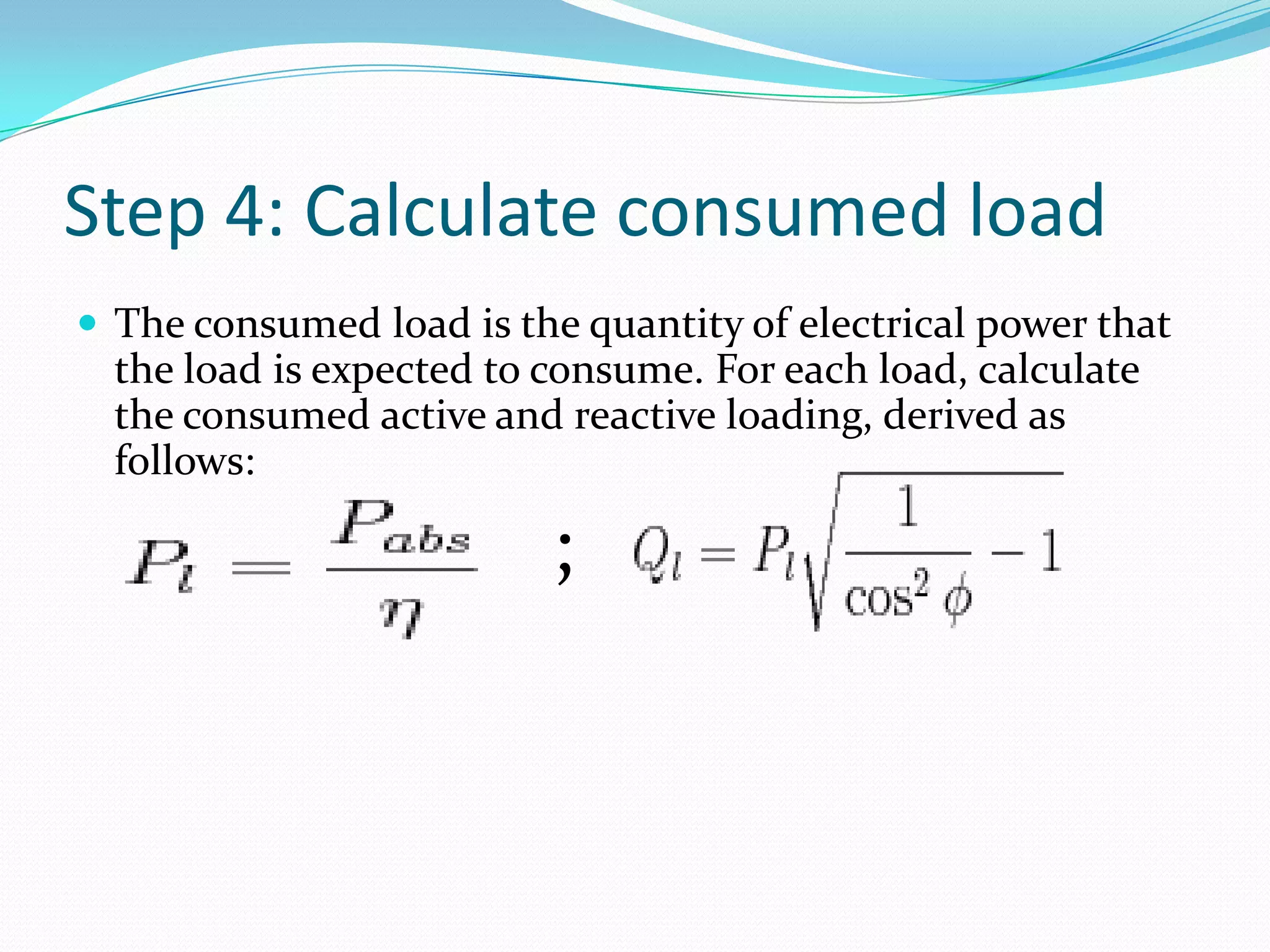
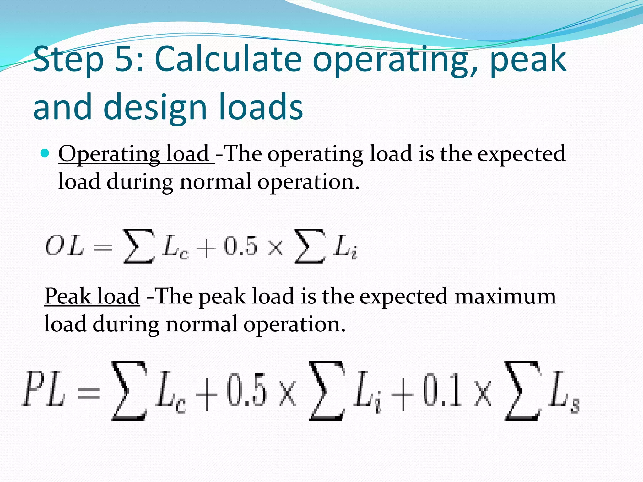
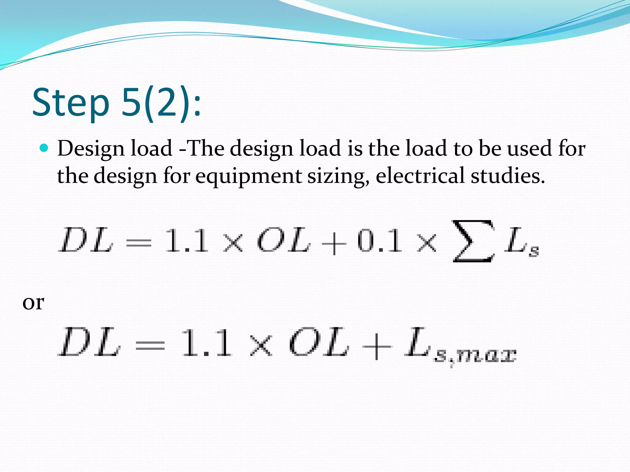
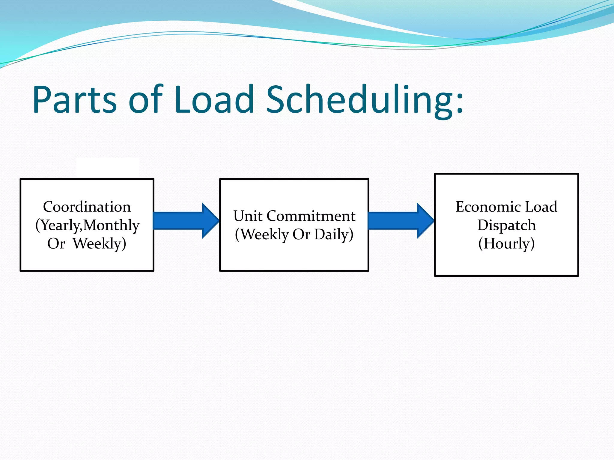


1. The document discusses the process of electrical load scheduling which involves estimating the instantaneous electrical loads in a facility in terms of active, reactive, and apparent power. 2. The key steps in load scheduling include collecting a list of expected loads, determining each load's electrical parameters, classifying loads, calculating each load's consumed power, and determining the operating, peak, and design loads. 3. Load scheduling is important for equipment sizing and power system studies to understand a facility's preliminary load details and provide input for the unit commitment and economic load dispatch problems.