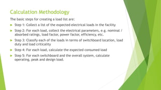
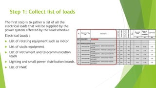
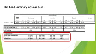
LOAD LIST 
WIWIT PURWANTO
The Electrical Load 
The part or component in a circuit that converts electricity into light, heat, or 
mechanical motion. Examples of loads are a light bulb, resistor, or motor.
Load Schedule/List 
 An estimate of the instantaneous electrical loads 
operating in a facility, in terms of active, reactive and 
apparent power (measured in kW, kVAr and kVA 
respectively). The load schedule is usually categorized by 
switchboard or occasionally by sub-facility / area.
Why do the calculation ? 
 Preparing the load list is one of the earliest tasks that 
needs to be done as it is essentially a pre-requisite for 
some of the key electrical design activities (such as 
equipment sizing and power system studies). 
 Equipment sizing : generator, transformer, cable, 
switchgear, bus duct, feeder, protection device ,etc. 
 Power system studies : power flow, short circuit, transient 
stability, harmonic, coordination of protection device, 
etc. 
 Balancing Load
When to do the calculation? 
 The electrical load schedule can typically be started with 
a preliminary key single line diagram (or at least an idea 
of the main voltage levels in the system) and any 
preliminary details of process / building / facility loads. It 
is recommended that the load list is started as soon as 
practically possible.
Calculation Methodology 
The basic steps for creating a load list are: 
 Step 1: Collect a list of the expected electrical loads in the facility 
 Step 2: For each load, collect the electrical parameters, e.g. nominal / 
absorbed ratings, load factor, power factor, efficiency, etc. 
 Step 3: Classify each of the loads in terms of switchboard location, load 
duty and load criticality 
 Step 4: For each load, calculate the expected consumed load 
 Step 5: For each switchboard and the overall system, calculate 
operating, peak and design load.
Example Load List :
Bus A Bus B 
Example
Step 1: Collect list of loads 
The first step is to gather a list of all the 
electrical loads that will be supplied by the 
power system affected by the load schedule. 
Electrical Loads : 
 List of rotating equipment such as motor 
 List of static equipment 
 List of instrument and telecommunication 
loads 
 Lighting and small power distribution boards. 
 List of HVAC
Step 2: Collect electrical load parameters 
A number of electrical load parameters are necessary to construct the load 
schedule: 
 Rated power 
 Absorbed power 
 Power factor 
 Efficiency
Step 3: Classify the loads 
Once the loads have been identified, they need to be classified accordingly: 
Voltage Level 
What voltage level and which switchboard should the load be located? Large 
loads may need to be on MV or HV switchboards depending on the size of the load 
and how many voltage levels are available. 
Load duty 
Loads are classified according to their duty as either continuous, intermittent 
and standby loads: 
 Continuous loads are those that normally operate continuously over a 24 hour 
period, e.g. process loads, control systems, lighting and small power 
distribution boards, UPS systems, etc. 
 Intermittent loads that only operate a fraction of a 24 hour period, e.g. 
intermittent pumps and process loads, automatic doors and gates, etc. 
 Standby loads are those that are on standby or rarely operate under normal 
conditions, e.g. standby loads, emergency systems, etc.
Step 4: Calculate consumed load 
The consumed load is the quantity of electrical power that the load is expected 
to consume. For each load, calculate the consumed active and reactive loading, 
derived as follows: 
Note : The loads have been categorized into three columns depending on their 
load duty (continuous, intermittent or standby).
Step 5: Calculate operating, peak and design loads 
Many organizations / clients have their own distinct method for calculating 
operating, peak and design loads, but a generic method is presented as follows: 
Operating load 
The operating load is the expected load during normal operation. The operating 
load is calculated as follows:
Peak load 
The peak load is the expected maximum load during normal operation. Peak 
loading is typically infrequent and of short duration, occurring when standby 
loads are operated (e.g. for changeover of redundant machines, testing of safety 
equipment, etc). The peak load is calculated as :
Design load 
The design load is the load to be used for the design for equipment sizing, 
electrical studies, etc. The design load is generically calculated as the larger of 
either: 
퐷퐿 = 1.2 ∗ 푃퐿 
Where DL : The design load ( kW or kVAr ) 
PL : The peak load ( kW or kVAr ) 
The design load includes a margin for any errors in load estimation, load growth 
or the addition of unforeseen loads that may appear after the design phase.
The Load Summary of Load List :

Load list calculation

  • 1.
  • 2.
    The Electrical Load The part or component in a circuit that converts electricity into light, heat, or mechanical motion. Examples of loads are a light bulb, resistor, or motor.
  • 3.
    Load Schedule/List An estimate of the instantaneous electrical loads operating in a facility, in terms of active, reactive and apparent power (measured in kW, kVAr and kVA respectively). The load schedule is usually categorized by switchboard or occasionally by sub-facility / area.
  • 4.
    Why do thecalculation ?  Preparing the load list is one of the earliest tasks that needs to be done as it is essentially a pre-requisite for some of the key electrical design activities (such as equipment sizing and power system studies).  Equipment sizing : generator, transformer, cable, switchgear, bus duct, feeder, protection device ,etc.  Power system studies : power flow, short circuit, transient stability, harmonic, coordination of protection device, etc.  Balancing Load
  • 5.
    When to dothe calculation?  The electrical load schedule can typically be started with a preliminary key single line diagram (or at least an idea of the main voltage levels in the system) and any preliminary details of process / building / facility loads. It is recommended that the load list is started as soon as practically possible.
  • 6.
    Calculation Methodology Thebasic steps for creating a load list are:  Step 1: Collect a list of the expected electrical loads in the facility  Step 2: For each load, collect the electrical parameters, e.g. nominal / absorbed ratings, load factor, power factor, efficiency, etc.  Step 3: Classify each of the loads in terms of switchboard location, load duty and load criticality  Step 4: For each load, calculate the expected consumed load  Step 5: For each switchboard and the overall system, calculate operating, peak and design load.
  • 7.
  • 8.
    Bus A BusB Example
  • 9.
    Step 1: Collectlist of loads The first step is to gather a list of all the electrical loads that will be supplied by the power system affected by the load schedule. Electrical Loads :  List of rotating equipment such as motor  List of static equipment  List of instrument and telecommunication loads  Lighting and small power distribution boards.  List of HVAC
  • 10.
    Step 2: Collectelectrical load parameters A number of electrical load parameters are necessary to construct the load schedule:  Rated power  Absorbed power  Power factor  Efficiency
  • 11.
    Step 3: Classifythe loads Once the loads have been identified, they need to be classified accordingly: Voltage Level What voltage level and which switchboard should the load be located? Large loads may need to be on MV or HV switchboards depending on the size of the load and how many voltage levels are available. Load duty Loads are classified according to their duty as either continuous, intermittent and standby loads:  Continuous loads are those that normally operate continuously over a 24 hour period, e.g. process loads, control systems, lighting and small power distribution boards, UPS systems, etc.  Intermittent loads that only operate a fraction of a 24 hour period, e.g. intermittent pumps and process loads, automatic doors and gates, etc.  Standby loads are those that are on standby or rarely operate under normal conditions, e.g. standby loads, emergency systems, etc.
  • 12.
    Step 4: Calculateconsumed load The consumed load is the quantity of electrical power that the load is expected to consume. For each load, calculate the consumed active and reactive loading, derived as follows: Note : The loads have been categorized into three columns depending on their load duty (continuous, intermittent or standby).
  • 13.
    Step 5: Calculateoperating, peak and design loads Many organizations / clients have their own distinct method for calculating operating, peak and design loads, but a generic method is presented as follows: Operating load The operating load is the expected load during normal operation. The operating load is calculated as follows:
  • 14.
    Peak load Thepeak load is the expected maximum load during normal operation. Peak loading is typically infrequent and of short duration, occurring when standby loads are operated (e.g. for changeover of redundant machines, testing of safety equipment, etc). The peak load is calculated as :
  • 15.
    Design load Thedesign load is the load to be used for the design for equipment sizing, electrical studies, etc. The design load is generically calculated as the larger of either: 퐷퐿 = 1.2 ∗ 푃퐿 Where DL : The design load ( kW or kVAr ) PL : The peak load ( kW or kVAr ) The design load includes a margin for any errors in load estimation, load growth or the addition of unforeseen loads that may appear after the design phase.
  • 16.
    The Load Summaryof Load List :