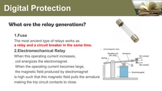
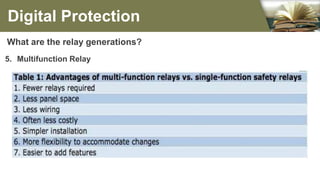
The document summarizes the different generations of electrical relays used in digital protection systems. It discusses fuse relays, electromechanical relays, solid state relays, digital relays, adaptive digital relays, multifunction relays, and intelligent relays. Electromechanical relays were prone to failures over time but newer digital and solid state relays are more reliable with no moving parts. Digital relays allow for more complex functions, self-testing, and communication compared to earlier relay technologies. Adaptive digital relays can automatically adjust settings based on changes in power system conditions. Multifunction relays provide multiple protection functions in a single unit to reduce space and wiring needs. Intelligent relays allow customers to change
How is power transformer protected??? This provides a basic understanding of power transformer. Furthermore, the protective relay application on power transformer is included.
Generation of High D.C. Voltage (HVDC generation)RP6997
Generation of high dc voltage using different methods like half wave and full wave rectifier, voltage doubler circuits, voltage multiplier circuits, cockcroft-walton circuits and van de graaff generators.
Distribution System Voltage Drop and Power Loss CalculationAmeen San
Distribution System Voltage Drop and Power Loss
Calculation
Comparison of Overhead Versus Underground System
Power Loss Calculation,Voltage Drop Calculation
FUNDAMENTALS OF POWER SYSTEM PROTECTION
FUNDAMENTALS OF POWER SYSTEM PROTECTIONFUNDAMENTALS OF POWER SYSTEM PROTECTIONFUNDAMENTALS OF POWER SYSTEM PROTECTIONFUNDAMENTALS OF POWER SYSTEM PROTECTIONFUNDAMENTALS OF POWER SYSTEM PROTECTIONFUNDAMENTALS OF POWER SYSTEM PROTECTIONFUNDAMENTALS OF POWER SYSTEM PROTECTIONFUNDAMENTALS OF POWER SYSTEM PROTECTIONFUNDAMENTALS OF POWER SYSTEM PROTECTIONFUNDAMENTALS OF POWER SYSTEM PROTECTIONFUNDAMENTALS OF POWER SYSTEM PROTECTIONFUNDAMENTALS OF POWER SYSTEM PROTECTIONFUNDAMENTALS OF POWER SYSTEM PROTECTIONFUNDAMENTALS OF POWER SYSTEM PROTECTIONFUNDAMENTALS OF POWER SYSTEM PROTECTIONFUNDAMENTALS OF POWER SYSTEM PROTECTIONFUNDAMENTALS OF POWER SYSTEM PROTECTIONFUNDAMENTALS OF POWER SYSTEM PROTECTIONFUNDAMENTALS OF POWER SYSTEM PROTECTIONFUNDAMENTALS OF POWER SYSTEM PROTECTIONFUNDAMENTALS OF POWER SYSTEM PROTECTIONFUNDAMENTALS OF POWER SYSTEM PROTECTIONFUNDAMENTALS OF POWER SYSTEM PROTECTIONFUNDAMENTALS OF POWER SYSTEM PROTECTIONFUNDAMENTALS OF POWER SYSTEM PROTECTIONFUNDAMENTALS OF POWER SYSTEM PROTECTIONFUNDAMENTALS OF POWER SYSTEM PROTECTIONFUNDAMENTALS OF POWER SYSTEM PROTECTIONFUNDAMENTALS OF POWER SYSTEM PROTECTIONFUNDAMENTALS OF POWER SYSTEM PROTECTIONFUNDAMENTALS OF POWER SYSTEM PROTECTIONFUNDAMENTALS OF POWER SYSTEM PROTECTIONFUNDAMENTALS OF POWER SYSTEM PROTECTIONFUNDAMENTALS OF POWER SYSTEM PROTECTIONFUNDAMENTALS OF POWER SYSTEM PROTECTIONFUNDAMENTALS OF POWER SYSTEM PROTECTIONFUNDAMENTALS OF POWER SYSTEM PROTECTIONFUNDAMENTALS OF POWER SYSTEM PROTECTIONFUNDAMENTALS OF POWER SYSTEM PROTECTIONFUNDAMENTALS OF POWER SYSTEM PROTECTIONFUNDAMENTALS OF POWER SYSTEM PROTECTIONFUNDAMENTALS OF POWER SYSTEM PROTECTIONFUNDAMENTALS OF POWER SYSTEM PROTECTIONFUNDAMENTALS OF POWER SYSTEM PROTECTIONFUNDAMENTALS OF POWER SYSTEM PROTECTIONFUNDAMENTALS OF POWER SYSTEM PROTECTIONFUNDAMENTALS OF POWER SYSTEM PROTECTION
Classification Of Power System StabilityAravind Shaji
The Slide Deals With Power System Stability. Contents Include
Power System Stability Overview
Power System Stability: A Proposed Definition
Need of Stability Classification
Classification of stability
Power System Stability Classification
Rotor Angle Stability
Voltage Stability
Frequency Stability
Rotor Angle Stability vs. Voltage Stability
References
In this presentation, we’ll describe types of fault in power system including :
Definition of Fault in Power System
Types of Fault and
A short description of various types of Fault
Electrical fault is the deviation of voltages and currents from nominal values or states. Under normal operating conditions, power system equipment or lines carry normal voltages and currents which results in a safer operation of the system.
In the modern power system the reactive power compensation is one of the main issues, the transmission of active power requires a difference in angular phase between voltages at the sending and receiving points (which is feasible within wide limits), whereas the transmission of reactive power requires a difference in magnitude of these same voltages (which is feasible only within very narrow limits). The reactive power is consumed not only by most of the network elements, but also by most of the consumer loads, so it must be supplied somewhere. If we can't transmit it very easily, then it ought to be generated where it is needed." (Reference Edited by T. J. E. Miller, Forward Page ix).Thus we need to work on the efficient methods by which VAR compensation can be applied easily and we can optimize the modern power system. VAR control technique can provides appropriate placement of compensation devices by which a desirable voltage profile can be achieved and at the same time minimizing the power losses in the system. This report discusses the transmission line requirements for reactive power compensation. In this report thyristor switched capacitor is explained which is a static VAR compensator used for reactive power management in electrical systems.
Seminar Topic For Electrical and Electronics Engineering (EEE)
These slides present the introduction to FACTS devices. Later we will discuss about its modelling and control aspect applications. This comes under the topic on power electronics application in smart and microgrid systems.
Types of Relay - Which One Should You UseWagoIndia
Looking for a reliable and easy-to-use relay module? Click here to explore range of WAGO relay and optocoupler modules for your application. Visit us at https://www.wago.com/in/interface-electronic/discover-relays-optocouplers
Relays classification–Instantaneous– DMT and IDMT types– Applications of relays: Over current and under voltage relays– Directional relays– Differential relays and percentage differential relays
Relays in industry and home aplycationsĽubomír Radič
Industrial Relays for industrial automation and process control.
Industrial switching devices, DIFFERENTIAL RELAYS, POWER RELAYS, TIME DELAY RELAYS, DIGITAL RELAYS,
SAFETY RELAYS, MONITORING RELAYS, DIFERENTIAL PROTECTION RELAYS, ELECTROMECHANICAL RELAYS, PCB POWER RELAYS
Here an electronic circuit breaker is designed which is based on the current sensing across a series element typically a CT (current Transformer). The current sensed which is compared against the preset value proportional to the voltage by comparator which is inbuilt in arduino to generate an output that drives a relay through a MOSFET to trip the load very fastly.
The concept of electronic circuit breaker came into focus realizing that the conventional circuit breakers such as MCBs take longer time to trip.
The steadily increasing population has more demand and consumption of electric energy in the market as raised and that of equipment’s used like electrical and electronics are also costlier
So to protect the electrical system from overload or short circuit here is one possibility, which is by ultrafast acting electronic circuit breaker
The electronic circuit breaker is based on the voltage drop across a series element proportional to the load current, typically a low -value resistor.
Lec 1_Introduction to Power System
Protection.pdfAhmedHElashry
Electric power system is composed of the
components or elements such as generators,
transformers, transmission lines and distribution
lines, bus bars and others. Short circuits and other
abnormal conditions in the power system are
common and can cause damage to power system
equipment.
Electric power system is composed of the
components or elements such as generators,
transformers, transmission lines and distribution
lines, bus bars and others. Short circuits and other
abnormal conditions in the power system are
common and can cause damage to power system
equipment.
Electric power system is composed of the
components or elements such as generators,
transformers, transmission lines and distribution
lines, bus bars and others. Short circuits and other
abnormal conditions in the power system are
common and can cause damage to power system
equipment.
Electric power system is composed of the
components or elements such as generators,
transformers, transmission lines and distribution
lines, bus bars and others. Short circuits and other
abnormal conditions in the power system are
common and can cause damage to power system
equipment.
Electric power system is composed of the
components or elements such as generators,
transformers, transmission lines and distribution
lines, bus bars and others. Short circuits and other
abnormal conditions in the power system are
common and can cause damage to power system
equipment.
Electric power system is composed of the
components or elements such as generators,
transformers, transmission lines and distribution
lines, bus bars and others. Short circuits and other
abnormal conditions in the power system are
common and can cause damage to power system
equipment.
Electric power system is composed of the
components or elements such as generators,
transformers, transmission lines and distribution
lines, bus bars and others. Short circuits and other
abnormal conditions in the power system are
common and can cause damage to power system
equipment.
Electric power system is composed of the
components or elements such as generators,
transformers, transmission lines and distribution
lines, bus bars and others. Short circuits and other
abnormal conditions in the power system are
common and can cause damage to power system
equipment.
Electric power system is composed of the
components or elements such as generators,
transformers, transmission lines and distribution
lines, bus bars and others. Short circuits and other
abnormal conditions in the power system are
common and can cause damage to power system
equipment.
Electric power system is composed of the
components or elements such as generators,
transformers, transmission lines and distribution
lines, bus bars and others. Short circuits and other
abnormal conditions in the power system are
common and can cause damage to power system
equipment.
Electric power system is composed of the
components or elements such as generators,
transformers, transmission lines and distribution
line
Industrial Training at Shahjalal Fertilizer Company Limited (SFCL)MdTanvirMahtab2
This presentation is about the working procedure of Shahjalal Fertilizer Company Limited (SFCL). A Govt. owned Company of Bangladesh Chemical Industries Corporation under Ministry of Industries.
Student information management system project report ii.pdfKamal Acharya
Our project explains about the student management. This project mainly explains the various actions related to student details. This project shows some ease in adding, editing and deleting the student details. It also provides a less time consuming process for viewing, adding, editing and deleting the marks of the students.
Saudi Arabia stands as a titan in the global energy landscape, renowned for its abundant oil and gas resources. It's the largest exporter of petroleum and holds some of the world's most significant reserves. Let's delve into the top 10 oil and gas projects shaping Saudi Arabia's energy future in 2024.
Sachpazis:Terzaghi Bearing Capacity Estimation in simple terms with Calculati...Dr.Costas Sachpazis
Terzaghi's soil bearing capacity theory, developed by Karl Terzaghi, is a fundamental principle in geotechnical engineering used to determine the bearing capacity of shallow foundations. This theory provides a method to calculate the ultimate bearing capacity of soil, which is the maximum load per unit area that the soil can support without undergoing shear failure. The Calculation HTML Code included.
Water scarcity is the lack of fresh water resources to meet the standard water demand. There are two type of water scarcity. One is physical. The other is economic water scarcity.
Final project report on grocery store management system..pdfKamal Acharya
In today’s fast-changing business environment, it’s extremely important to be able to respond to client needs in the most effective and timely manner. If your customers wish to see your business online and have instant access to your products or services.
Online Grocery Store is an e-commerce website, which retails various grocery products. This project allows viewing various products available enables registered users to purchase desired products instantly using Paytm, UPI payment processor (Instant Pay) and also can place order by using Cash on Delivery (Pay Later) option. This project provides an easy access to Administrators and Managers to view orders placed using Pay Later and Instant Pay options.
In order to develop an e-commerce website, a number of Technologies must be studied and understood. These include multi-tiered architecture, server and client-side scripting techniques, implementation technologies, programming language (such as PHP, HTML, CSS, JavaScript) and MySQL relational databases. This is a project with the objective to develop a basic website where a consumer is provided with a shopping cart website and also to know about the technologies used to develop such a website.
This document will discuss each of the underlying technologies to create and implement an e- commerce website.
Hybrid optimization of pumped hydro system and solar- Engr. Abdul-Azeez.pdffxintegritypublishin
Advancements in technology unveil a myriad of electrical and electronic breakthroughs geared towards efficiently harnessing limited resources to meet human energy demands. The optimization of hybrid solar PV panels and pumped hydro energy supply systems plays a pivotal role in utilizing natural resources effectively. This initiative not only benefits humanity but also fosters environmental sustainability. The study investigated the design optimization of these hybrid systems, focusing on understanding solar radiation patterns, identifying geographical influences on solar radiation, formulating a mathematical model for system optimization, and determining the optimal configuration of PV panels and pumped hydro storage. Through a comparative analysis approach and eight weeks of data collection, the study addressed key research questions related to solar radiation patterns and optimal system design. The findings highlighted regions with heightened solar radiation levels, showcasing substantial potential for power generation and emphasizing the system's efficiency. Optimizing system design significantly boosted power generation, promoted renewable energy utilization, and enhanced energy storage capacity. The study underscored the benefits of optimizing hybrid solar PV panels and pumped hydro energy supply systems for sustainable energy usage. Optimizing the design of solar PV panels and pumped hydro energy supply systems as examined across diverse climatic conditions in a developing country, not only enhances power generation but also improves the integration of renewable energy sources and boosts energy storage capacities, particularly beneficial for less economically prosperous regions. Additionally, the study provides valuable insights for advancing energy research in economically viable areas. Recommendations included conducting site-specific assessments, utilizing advanced modeling tools, implementing regular maintenance protocols, and enhancing communication among system components.
Overview of the fundamental roles in Hydropower generation and the components involved in wider Electrical Engineering.
This paper presents the design and construction of hydroelectric dams from the hydrologist’s survey of the valley before construction, all aspects and involved disciplines, fluid dynamics, structural engineering, generation and mains frequency regulation to the very transmission of power through the network in the United Kingdom.
Author: Robbie Edward Sayers
Collaborators and co editors: Charlie Sims and Connor Healey.
(C) 2024 Robbie E. Sayers
Hierarchical Digital Twin of a Naval Power SystemKerry Sado
A hierarchical digital twin of a Naval DC power system has been developed and experimentally verified. Similar to other state-of-the-art digital twins, this technology creates a digital replica of the physical system executed in real-time or faster, which can modify hardware controls. However, its advantage stems from distributing computational efforts by utilizing a hierarchical structure composed of lower-level digital twin blocks and a higher-level system digital twin. Each digital twin block is associated with a physical subsystem of the hardware and communicates with a singular system digital twin, which creates a system-level response. By extracting information from each level of the hierarchy, power system controls of the hardware were reconfigured autonomously. This hierarchical digital twin development offers several advantages over other digital twins, particularly in the field of naval power systems. The hierarchical structure allows for greater computational efficiency and scalability while the ability to autonomously reconfigure hardware controls offers increased flexibility and responsiveness. The hierarchical decomposition and models utilized were well aligned with the physical twin, as indicated by the maximum deviations between the developed digital twin hierarchy and the hardware.
1. A Report on Digital protection
Electrical Relays
6th December 2017
By
Mahmoud Magdi Mohamed
Prof. Hany M. Amin Elghazaly
ELECTRIC POWER AND MACHINES DEPARTMENT
3. What is The Relay?
Relay is a device that sense volt and current values & compare
them with the setting values so the circuit breaker will be able
to make a decision by tripping or not as quickly as possible to
return the power system to its normal state .
Digital Protection
4. What are the relay generations?
1.Fuse
The most ancient type of relays works as
a relay and a circuit breaker in the same time.
2.Electromechanical Relay
When this operating current increases,
coil energizes the electromagnet.
When the operating current becomes large,
the magnetic field produced by electromagnet
is high such that this magnetic field pulls the armature
making the trip circuit contacts to close.
Digital Protection
5. Electromechanical Relay
Disadvantages :
Electromechanical relays are prone to failures due to factors that may not affect s
olid-state or digital relays such as:
1. Aging that change a component’s characteristic (for example moving springs force) d
ue to temperature variations, dirt on discs, oxides that increase the resistance
2. High burden level instrument transformers are required
(CTs and PTs of high burden is required for operating the electromagnetic relays
compared to static relays.)
3. The directional feature is absent in electromagnetic relay.
4. The operating time is relatively slow due to friction issue.
5. Multifunctioning is not possible. One relay can perform only one function
Digital Protection
6. What are the relay generations?
3.Solid state or Static Relay
What is a solid state relay ?
SSRs (Solid State Relays) have no movable contacts.
SSRs are not very different in operation from mechanical relays
that have movable contacts. SSRs, however, employ semiconductor
switching elements, such as thyristors, triacs, diodes, and transistors.
SSRs employ optical semiconductors called photocouplers
to isolate input and output signals.
Photocouplers change electric signals into optical signals and relay the signals through space,
thus fully isolating the input and output sections while relaying the signals at high speed.
Digital Protection
7. Solid state relays and optocouplers
Photocouplers or optocouplers :
An optocoupler (or an optoelectronic coupler) is basically an interface
between two circuits which operate at (usually) different voltage levels.
The key advantage of an optocoupler is the electrical isolation between
the input and output circuits. With an optocoupler, the only
contact between the input and the output is a beam of light
Digital Protection
8. What are the relay generations?
3. Solid state or Static Relay
What is a solid state relay ?
SSRs consist of electronic parts with no mechanical contacts.
Therefore, SSRs have a variety of features that mechanical relays doesn’t have.
The greatest feature of SSRs is that SSRs do not use switching contacts
that will physically wear out.
SSRs are ideal for a wide range of applications due to the following performance characteristics.
・ They provide high-speed, high-frequency switching operations.
・ They have no contact failures.
・ They generate little noise.
・ They have no operation noise
Digital Protection
9. Solid state relays Electromechanical relays
Electrical noise
• Generate minimal electrical
disturbance
• Generate noise due to
mechanical movement
Power
consumption
• Low power consumption
• Function of switching voltage
and internal resistance
• Require higher input power to
operate
Shock and
vibrations
• Resist shocks and vibrations
• Operate in harsh environm
ents (mechanical strains )
• When subjected to external
forces or vibration can
operate erratically
Switching time
• Respond to control signals i
n less than 100 µs
• Needs 5-15 ms to respond
(100 times slower)
Solid State Relays Vs Em. Relays
10. Advantages And Disadvantages
Advantages.
1. There is no mechanical parts as it operates through comparators
(ex.: transistors) and its output is energized to the trip coil.
1. Output resistance remains constant regardless of amount of use.
2. No sparking, allows it to be used in explosive environments.
(petroleum)
3. Solid-state relays have burdens of 0.5 VA or less and do not
change with tap setting.
Disadvantages.
1.The components very sensitive for temperature rise.
2.Solid-state relays also require independent power supplies, since
springs and driving torques from the input quantities are not present.
3.Voltage/current characteristic is not linear (not purely resistive)
because of using semiconductors.
11. What are the relay generations?
4. Digital relay
What is a digital relay ?
The idea of innovating a digital relay was presented in a paper by Rock filler in 1969.
But, the first digital relay was manufactured later on by Siemens in 1975.
Digital relaying involves digital processing of one or more analog signals
in three steps:
1. Conversion Of Analogue Signal To Digital Form
2. Processing Of Digital Form
3. Boolean Decision To Trip Or Not To Trip.
Digital Protection
12. What are the relay generations?
4. Digital relay
What is a digital relay ?
Digital relay consists of:
1. Analogue input subsystem,
2. Digital input subsystem,
3. Digital output subsystem,
4. A processor along with RAM (data scratch pad),
5. main memory (historical data file)
6. Power supply
Digital Protection
13. What are the relay generations?
4. Digital relay
How does it work ?
• The Microprocessor sends command signal to read input data.
• The Input data is fed to analog to digital converter (ADC) to obtain signal in
digital form.
• Microprocessor then compares the data with pick-up value.
• If the input is greater than pick-up value the microprocessor send a trip
signal to circuit breaker of the desired circuit.
Digital Protection
14. What are the relay generations?
4. Digital relay
Why Numerical Relaying?
• Numerical relays permit much more flexibility than their electromechanical and solid state
counterparts.
• The digital relay can emulate functions of many discrete electromechanical relays in one device,
simplifying protection design and maintenance.
• Each digital relay can run self-test routines to confirm its readiness and alarm if a fault is
detected and hence it is more reliable.
• Digital relays can, for example, store multiple sets of protection parameters, which allows the
behavior of the relay to be changed during maintenance of attached equipment.
Digital Protection
15. What are the relay generations?
4. Digital relay
In A Nutshell
• Additional monitoring functions
• Functional flexibility.
• Capable of working under a wide range of temperatures.
• They can implement more complex function and are generally more accurate
• Self-checking and self-adaptability.
• Able to communicate with other digital equipment (pear to pear).
• Less sensitive to temperature, aging
Watchdog property !!!
Digital Protection
16. Watchdog property !!!
• During normal operation, the computer regularly restarts the watchdog timer
to prevent it
from elapsing, or "timing out".
• If, due to a hardware fault or program error, the computer fails to restart the
watchdog,
• the timer will elapse and generate a timeout signal.
• The timeout signal is used to initiate corrective action or actions.
• The corrective actions typically include placing the computer system in a sa
fe state and restoring normal system operation
Digital Protection
17. What are the relay generations?
4. Digital relay
Limitations of Digital Relay
• Short lifetime due to the continuous development of new technologies.
The devices become obsolete rapidly.
• Susceptibility to power system transients.
• As digital systems become increasingly more complex they require specially trained staff for
Operation. Proper maintenance of the settings and monitoring data.
Digital Protection
18. What are the relay generations?
4. Adaptive digital relay
Adaptive Relaying permits and seeks to make adjustments automatically in various protections
in order to make them attuned to power system conditions. In this relay type, relay can sense any
variation & check first before making a decision as variation may happened due to normal operatio
n or abnormal operation.
Digital Protection
If the variation is caused by normal operation, relay setting should
be changed based on a group of setting as in the
(Figure Relay should follow load variations)
19. What are the relay generations?
4. Adaptive digital relay
Conventional relays have fixed setting parameters and therefore it becomes difficult to comply with
the protection requirements in variable operation conditions in a power system. A solution to this
problem is the adaptive protection, which can vary its setting parameters or its operating
characteristics in response to changes in the power system.
Adaptive protection is defined as “a protection philosophy which permits and seeks to make
adjustments to various protection functions in order to make them more attuned to
prevailing power system conditions.”
. This change in power system topology is mainly due to the following reasons :
1. Deliberate system switching, for example, isolation of a part of the equipment for
maintenance.
2. Unplanned system switching, for example, removal of a fault by a relay from a healthy
power system.
Digital Protection
20. What are the relay generations?
4. Adaptive digital relay
In these cases, the power system topology gets changed but the system protection settings
remain the same as they before the modifications, which is why the latter may not be able to
adequately protect the current system.
Adaptive relaying can be utilized in the following areas:
• Automatic circuit breaker reclosing control.
• Power transformer protection.
• Multi-terminal transmission line protection. If both the relays sense a fault in their respective
zones of protection. The relay with the shorter time delay or the relay subject to the longer fault
current should trip first.
• Relay settings. As the power system topology changes, the relay will automatically switch to the
appropriate relay group for proper power system protection.
Digital Protection
21. What are the relay generations?
5. Multifunction Relay
A multifunction digital relay is a microprocessor-based unit that uses Digital Signal Processing
technology in order to provide multiple protective relaying functions for protection in one unit.
This will lead to decrease panel space and wiring is required than would be if individual relays
were used
Advantages
• Decreasing the number of wiring and also the time of maintenance.
• provide a high level of protection at a very attractive cost
Disadvantage
• Power supply loss failure (can be solved by using a backup power supply).
• Subroutine failure ( can be solved by using electromagnetic as a backup protection)
Digital Protection
22. What are the relay generations?
5. Multifunction Relay
Digital Protection
23. What are the relay generations?
6. Intelligent Relay
Intelligent (numerical) relays are micro processor based relays and having the features of customer
changed functions.
Digital Protection