Downloaded 1,155 times


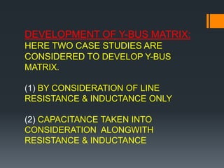


This document discusses constraints and load flow analysis in power systems. It outlines four key constraints: active power constraint, reactive power constraint, voltage magnitude constraint, and load angle constraint. It also describes load flow analysis as a balanced mechanism between demand and generation under incremental loading. Load flow analysis is important for the safe and future operation of power systems. The document further discusses bus classification, basic power flow conditions including the proportional relationships between reactive power and voltage and active power and load angle. It also covers the development of the Y-bus matrix considering line resistances and inductances alone and then including line capacitances.


![15ee81 module1[www.vtuloop.com].pdf](https://cdn.slidesharecdn.com/ss_thumbnails/15ee81module1www-230201160325-adb6d6ab-thumbnail.jpg?width=640&height=640&fit=bounds)