Downloaded 2,591 times


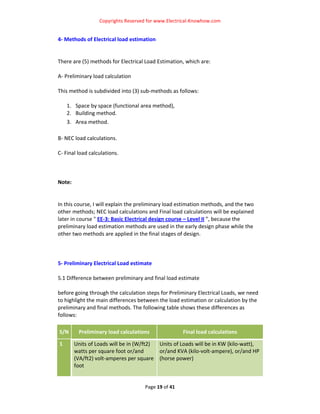


This document provides an overview of electrical load estimation and definitions of important terms used in load estimation calculations. It describes the importance of preliminary load estimation in the early design stage to plan power supply and infrastructure. Key terms are defined, including connected load, demand load, demand interval, maximum demand, demand factor, coincidence factor, and diversity factor. Different methods for performing preliminary load estimation calculations are also outlined, including the space-by-space method, building method, and area method.


