Download as PDF, PPTX
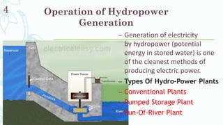
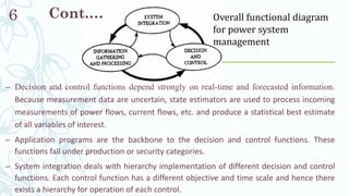

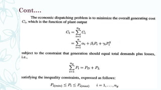
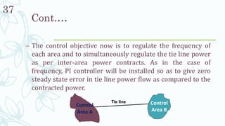


The document discusses power system operation, focusing on hydropower generation, energy management systems, and the control mechanisms necessary for optimal system operation. It outlines the importance of maintaining balance between generation and demand, as well as various methods for voltage and frequency control. Additionally, it highlights economic dispatch strategies to minimize production costs while ensuring reliability and stability of power supply.


![Power system planning & operation [eceg 4410]](https://cdn.slidesharecdn.com/ss_thumbnails/powersystemplanningoperationeceg-4410-130607134359-phpapp01-thumbnail.jpg?width=640&height=640&fit=bounds)


![15ee81 module1[www.vtuloop.com].pdf](https://cdn.slidesharecdn.com/ss_thumbnails/15ee81module1www-230201160325-adb6d6ab-thumbnail.jpg?width=640&height=640&fit=bounds)