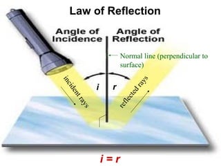
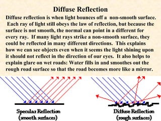
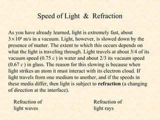
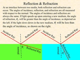
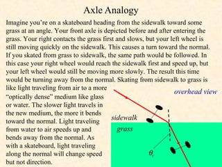
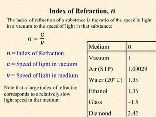
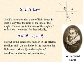
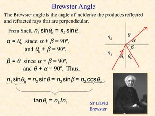
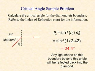
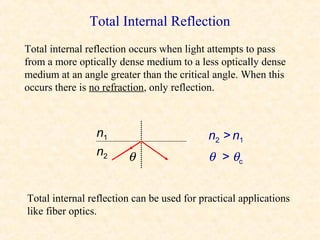
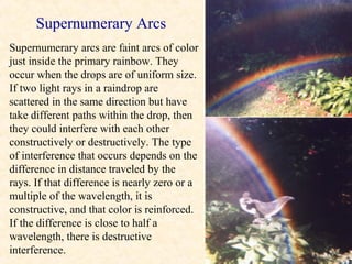
Optics involves the reflection and refraction of light. Reflection occurs when light bounces off a surface, following the law of reflection where the angle of incidence equals the angle of reflection. Refraction is when light changes speed and direction when passing from one medium to another due to a change in index of refraction. Refraction is described by Snell's law, where the ratio of sines of the incident and refracted angles is equal to the ratio of the indices of refraction. Total internal reflection occurs when light passes from a higher to lower index of refraction beyond the critical angle and is completely reflected rather than refracted.
This document describes a physics course on optics taught at the National Institute of Technology in Rourkela, India. The course covers topics such as wave optics, interference, diffraction, polarization, and quantum mechanics. It provides details on class times, the instructor, grading criteria, assignments, textbook references, and sample topics that will be covered, such as Young's double slit experiment, interference conditions, and optical path differences.
Refraction and Snell's Law describes how light bends when passing from one medium to another due to a change in speed. Refraction occurs at the boundary between two media, with the incident ray entering the first medium at an angle of incidence, and the refracted ray exiting the second medium at an angle of refraction. Snell's law states that the ratio of the sines of the angles of incidence and refraction is equal to the ratio of the indices of refraction of the two media. This relationship is written as an equation that can be used to calculate angles of refraction based on the incident angle and refractive indices. Each material has its own index of refraction value that determines how much light will bend when
Light is necessary for sight and interacts with the eyes and brain to allow us to see. Reflection occurs when light changes direction at the interface between two different media, following the law that the angle of incidence equals the angle of reflection. Refraction is when a light ray changes direction and speed as it passes from one medium to another due to a change in density.
This document discusses the principles and phenomena of diffraction. It begins by defining diffraction as the deviation of light from rectilinear propagation that occurs when a portion of a wavefront is obstructed. The Huygens-Fresnel principle is introduced, which states that every point on a wavefront acts as a secondary source of spherical wavelets. Diffraction patterns can be classified as either Fraunhofer or Fresnel diffraction depending on the separation between the aperture and viewing screen. Examples of diffraction from single slits, circular apertures, and double slits are analyzed. Rayleigh's criterion for resolving power with rectangular apertures is also described.
Light is visible electromagnetic radiation that travels in packets called photons. It can come from natural sources like the sun or artificial sources like light bulbs. Refraction is when light changes speed and direction as it passes from one medium to another, like from water to air, causing objects to appear bent. The refractive index measures how much light slows down in a medium and is used to describe materials like glass. Optics is the study of light and its interactions with lenses and other components, which can be used to focus, spread, or diffuse light through different lens shapes like concave, convex, plano, and Fresnel lenses.
Optics is the study of light, including its interactions with matter. There are three main subfields: geometrical optics studies light as rays, physical optics studies light as waves, and quantum optics studies light as particles. Mirrors form images through the reflection of light rays according to specific rules. Plane mirrors form virtual upright images that are laterally inverted. Spherical mirrors can be concave or convex and form images using rules for tracing the path of light rays. Constructing ray diagrams involves using rays that pass through the center of curvature, focal point, or pole to locate the image point.
This document provides an overview of geometric optics, including reflection, mirrors, refraction, and lenses. It discusses how light rays reflect off mirrors according to the law of reflection, forming real images with plane mirrors and virtual images with spherical mirrors, whether concave or convex. Concave mirrors bring parallel rays to a focus at their focal point, while convex mirrors cause parallel rays to appear to diverge from a virtual focal point.
Polarization of Light and its Application (healthkura.com)Bikash Sapkota
Download link ❤❤https://healthkura.com/eye-ppt/29/❤❤
Dear viewers Check Out my other piece of works at ❤❤❤ https://healthkura.com/eye-ppt/ ❤❤❤
polarization of light & its application.
PRESENTATION LAYOUT
Concept of Polarization
Types of Polarization
Methods of achieving Polarization
Applications of Polarization
POLARIZATION
Transforming unpolarized light into polarized light
Restriction of electric field vector E in a particular plane so that vibration occurs in a single plane
Characteristic of transverse wave
Longitudinal waves can’t be polarized; direction of their oscillation is along the direction of propagation.............
For Further Reading
•Optics by Tunnacliffe
•Optics and Refraction by A.K. Khurana
•Principle of Physics, Ayam Publication
•Internet
Total Internal Reflection and Critical AngleAmit Raikar
This document discusses total internal reflection and the critical angle. It defines refractive index as the ratio of light speed in a vacuum to light speed in a medium. When light passes from one medium to another of different density, refraction occurs. As the angle of incidence increases, so does the angle of refraction, until reaching the critical angle. At the critical angle, the light ray follows the surface instead of entering the second medium. Above the critical angle, total internal reflection occurs and the light is reflected back into the first medium. Total internal reflection and critical angles depend on the refractive indices of the materials, and have applications in fiber optics, prisms, periscopes, and more.
There are two main types of telescopes: Keplerian/astronomical telescopes and Galilean telescopes. Keplerian telescopes produce an inverted image while Galilean telescopes produce an upright image. Telescopes can be modified to compensate for refractive errors by adding lenses or changing the tube length to allow viewing of objects that are not at optical infinity.
The document discusses the phenomenon of interference of light. It explains the conditions required for interference, including coherent sources, monochromatic light, and a constant path difference. It describes several classic interference experiments, including Young's double slit experiment, Fresnel's bi-prism, Newton's rings, and Michelson's interferometer. It discusses how interference patterns are used to determine properties like wavelength and refractive index.
When waves encounter obstacles like slits, they diffract or bend around the edges. Diffraction can be explained by Huygens' principle, which says each point on a wavefront acts as a new source. For a single slit, the new wavefront shape is determined by combining spherical wavelets from points across the slit. There are two types of diffraction: Fresnel, where distances are finite, and Fraunhofer, where incident waves are plane waves. X-ray diffraction uses wavelengths comparable to atomic sizes to determine crystal and molecular structures.
Optics is the study of light and its interactions with objects like mirrors, lenses, and substances that reflect, scatter, or transmit light. When light strikes an object, it can be reflected, transmitted, scattered, or absorbed. There are three main types of mirrors - plane, concave, and convex - and reflection follows the rule that the angle of incidence equals the angle of reflection. Refraction occurs when light changes speed as it passes from one medium to another, causing it to bend. Lenses use refraction to form real or virtual images depending on the position of objects in relation to the focal point.
Refraction is the bending of light when it passes from one medium to another. Light travels at different speeds in different media, causing it to change direction at the boundary between the two. The degree to which light is refracted depends on the index of refraction, which is a ratio comparing the speed of light in a medium to the speed of light in a vacuum. White light disperses into the colors of the visible spectrum when refracted due to different wavelengths bending by different amounts.
Lenses are transparent materials that refract light in a predictable way. They are used to magnify or project images. There are two main types of lenses: convex and concave. Convex lenses are thicker in the center and converge light, forming a real image. Concave lenses are thinner in the center and diverge light, forming a virtual upright image that is smaller than the object. The way light rays behave when passing through lenses can be depicted using ray diagrams to show the characteristics of the image formed.
This PPT gives an elementary idea about dispersion. The dispersion through prism is discussed in some details & combination of prisms are made to make either dispersion or deviation to be equal to zero.
Refraction is the bending of light when passing from one medium to another. It occurs because the speed of light is decreased in denser mediums, causing the light's path to bend toward the normal. Snell's law describes the mathematical relationship between the angle of incidence and angle of refraction, stating that for two mediums, the ratio of sines of the incidence and refraction angles is equal to the ratio of the indexes of refraction. The index of refraction is a number that represents how much a medium slows light down relative to a vacuum.
This document provides an overview of optics and light, including:
1) It defines key wave properties like wavelength and frequency, and describes longitudinal and transverse waves. 2) It introduces the electromagnetic spectrum and explains how different frequencies are classified. 3) It covers geometric optics concepts such as reflection, refraction, mirrors, lenses and image formation using ray diagrams. Sign conventions are also defined for analyzing optical systems.
This document discusses refraction and lenses. It begins by explaining that refraction occurs when light passes from one medium to another, causing its velocity and path to change. It then discusses how lenses work, noting that there are two basic types: convex and concave lenses. Convex lenses converge light rays to a focal point, while concave lenses diverge light rays. The document provides examples of how light rays behave when passing through lenses and the characteristics of images formed, such as location, size, and orientation. It concludes by introducing the lens formula, which relates the focal length, object distance, and image distance.
Light refracts when passing from one medium to another with a different density. When light travels from a less dense to a more dense medium, it bends toward the normal, and when traveling from more dense to less dense, it bends away from the normal. The refractive index is a ratio of the speed of light in a vacuum to the speed in a particular medium, and is represented by the Greek letter μ. Snell's law describes the relationship between the angles of incidence and refraction.
Polarization is a property of transverse waves where the oscillations occur in one direction rather than randomly in all directions perpendicular to the propagation direction. Unpolarized waves have oscillations in any direction, while linearly polarized waves oscillate in only one direction. Polarization of electromagnetic waves is defined by the electric field. Polarization can occur through selective absorption by materials that preferentially absorb certain oscillation directions, such as Polaroid which absorbs oscillations parallel to its long molecular chains. Many applications rely on polarization, including Polaroid sunglasses, LCD displays, and antennas.
1) The document discusses key concepts of light including its properties, reflection, refraction, total internal reflection, and optical fibers.
2) It describes how light travels very fast in straight lines, and how we see objects because light reflects into our eyes from them. Shadows are formed when light is blocked.
3) Reflection and refraction of light follow specific laws, such as the law of reflection where the angle of incidence equals the angle of reflection, and Snell's law relating the indices of refraction and angles of light passing through different mediums.
Light is part of the electromagnetic spectrum that is visible to the human eye. It travels in straight lines called rays. Reflection is when light bounces off a surface, following the laws that the angle of incidence equals the angle of reflection and that the incident, normal, and reflected rays lie in the same plane. Refraction is when light changes speed and direction as it passes from one medium to another due to the different refractive indices, following Snell's law. Total internal reflection occurs when light cannot pass from an optically denser medium to a less dense one if the angle of incidence exceeds the critical angle.
The document discusses the principles of image formation using lenses and how lenses are used in corrective lenses. It covers the basics of refraction, how converging and diverging lenses form images using ray tracing rules, and examples of how converging and diverging lenses can correct for nearsightedness and farsightedness by forming intermediate images at the appropriate focal points for the eye. Diagrams illustrate the ray tracing and image formation for different types of lenses. Exercises provide examples of using the ray tracing rules to locate images.
1) The document discusses Fermat's principle of least time, which states that light travels along the path that takes the least amount of time between two points.
2) It uses Fermat's principle to derive the three fundamental laws of geometrical optics: rectilinear propagation, reflection, and refraction.
3) For reflection, it shows that applying Fermat's principle results in the angle of incidence equaling the angle of reflection. For refraction, it derives Snell's law which relates the sines of the angles of incidence and refraction.
A normally clear substance can appear colorful when found in a very thin layer due to constructive and destructive interference of light waves. When light hits the surface of a thin film, some light is reflected and some passes through, with further reflections and refractions at each boundary. The thickness of the film determines whether light waves interfere constructively or destructively, producing different colors. For example, a soap bubble appears green when the thickness of the soapy water layer is approximately 95.8 nm.
The document discusses refraction rules for converging and diverging lenses. It states that for a converging lens, any ray parallel to the principal axis will pass through the focal point on the opposite side, and any ray through the focal point will exit parallel to the principal axis. For a diverging lens, any ray parallel to the principal axis will pass through the focal point, and any ray toward the focal point will exit parallel to the principal axis. Additionally, any ray passing through the center of either lens will continue in the same direction.
Optics is the study of light and how it interacts with mirrors and lenses. Light travels in straight lines and can be reflected or refracted when it hits a surface. Reflection occurs when light bounces off a surface at the same angle, while refraction causes light to bend when moving between materials of different densities. Plane mirrors produce virtual images using the law of reflection. Spherical mirrors can produce virtual or real images depending on whether the object is inside or outside the focal length. Refraction is governed by Snell's law and causes light to bend when passing through materials like glass or water.
This document discusses the electromagnetic spectrum and properties of light. It explains that light can be described as both a wave and particle. The visible light spectrum is a small portion of the full electromagnetic spectrum. Different frequencies of light correspond to different colors, from red to violet. The speed of light is constant, and the frequency and wavelength of a light wave are related by the equation c=λν. Spectral lines allow scientists to identify elements and study distant stars and galaxies.
Here is a ray diagram showing why the chopstick looks bent when dipped into water:
air
water
incident ray refracted ray
normal
The diagram shows a ray of light traveling from air into water at the tip of the chopstick. Due to the change in refractive index, the light ray bends towards the normal as it enters the water. This makes the tip of the chopstick appear higher and causes the illusion that the chopstick is bent.
Light propagates in straight lines and can be reflected, refracted, and diffracted when interacting with matter. Reflection occurs when light hits a smooth surface and bounces back into the same medium at the same angle. Regular reflection occurs from plane mirrors where the angle of incidence equals the angle of reflection. Spherical mirrors can be concave or convex. Concave mirrors form real, inverted images, while convex mirrors form virtual, upright images. The mirror equation relates the focal length and distances of the object and image.
The document discusses different optical devices including lenses, mirrors, and prisms. It focuses on spherical mirrors, describing the two types - concave and convex mirrors. Key details are provided on the center of curvature, radius of curvature, principal axis, pole, focus, and focal length. The mirror formula relating object distance, image distance, and focal length is defined. Characteristics of images formed by concave and convex mirrors in different situations are explained. Uses of concave and convex mirrors are also noted.
The document discusses 3D holographic projection technology. It begins by defining holography as a technique that allows light scattered from an object to be recorded and later reconstructed, preserving the object's 3D information. It then covers the basics of how holograms work and are made, including recording the interference pattern of an object beam and reference beam, and reconstructing the hologram by illuminating the recorded pattern with the original light source. The document concludes by discussing advances and applications of holographic technology, such as touchable holograms and its potential to replace displays in the future.
The document discusses the refraction of light, including:
- Refraction occurs when light passes from one medium to another, changing direction.
- The refractive index is a ratio used to calculate the angle of refraction based on the angle of incidence.
- Total internal reflection occurs when light passes from an optically dense medium to a less dense one at an angle greater than the critical angle, causing the light to reflect within the dense medium.
this action research is basically done on Class 7th students.. They feel difficulty on spherical mirrors and lenses.So, in this research I'll try to solve thei problems as much as I canr
Science Facts - Check our astonishing compiliation of random and science facts.
Visit us at http://mesmerizeus.com or follow us at https://www.facebook.com/mesmerizerz
The document defines key optics terms including: plane, convex, and concave mirrors and lenses and how they affect light rays and images. It discusses the differences between convex and concave lenses and mirrors, and how they produce upright or inverted, magnified or minified images. The document also briefly mentions far-sightedness and near-sightedness in relation to convex and concave lenses.
The flow of energy in an ecosystem begins with autotrophs, such as plants, which use energy from the sun to produce their own food through photosynthesis. Heterotrophs, including herbivores, carnivores, omnivores, and decomposers then obtain energy by consuming autotrophs and other organisms. This energy is transferred between trophic levels in a food chain and food web, with less energy being available at higher trophic levels due to energy being lost as heat at each transfer.
This document discusses energy transfer and heat, defining key concepts like temperature, heat capacity, enthalpy, and calorimetry. It explains that enthalpy is a measure of the total energy of a system and can be used to calculate the energy change of chemical reactions using Hess's law by adding the enthalpy changes of individual steps. Calorimetry is used to experimentally measure enthalpy changes.
Reflection and Refraction of Optical Rays.
For comments, please contact me at solo.hermelin@gmail.com.
For more presentations on different topics visit my website at http://www.solohermelin.com.
This presentation is in the Optics folder.
Myopia can be corrected using concave lenses and hypermetropia can be corrected using convex lenses. Crabs have small eyes but can see all around using them. Owls have large corneas and pupils to let in more light as their retinas have more rods than cones, unlike day birds which have more cones and less rods.
The document summarizes key political and economic developments in Argentina between 1916-1943, a period that included the Great Depression. It notes that Argentina transitioned to democracy in 1916 with the election of Hipolito Yrigoyen and his Radical Party, until a 1930 military coup began a decade-long dictatorship. The coup was influenced by economic struggles during the Great Depression, as Argentina's agricultural export-based economy suffered from falling global demand. The dictatorship pursued import substitution industrialization policies to reduce foreign dependence and stimulate domestic industry, though this further hurt agriculture. Subsequent leaders after the 1943 coup attempted reforms toward greater democracy and economic stability.
This document provides a summary of light reflection and refraction. It begins by explaining that light travels in a straight line until it meets a boundary, where it can be reflected, refracted, or absorbed. It then discusses the laws of reflection, including that the incident, reflected, and normal rays lie in the same plane and that the angle of incidence equals the angle of reflection. Next, it explains refraction when light passes from one medium to another and discusses the relationship between incident and refracted angles. The remainder of the document analyzes light reflection and refraction using spherical mirrors and lenses through diagrams and explanations of six cases for each. It concludes by thanking various resources used to create the summary.
Trivia Questions For Science 8 Review Optics Quiz #2chathomeworkclub
According to the ray model of light, light travels in a straight line. When light hits a translucent surface it is scattered, and transparent materials let light pass through unobscured. Cardboard is opaque as it does not let light pass through, while wax paper is translucent since it scatters light. The object with the larger shadow is closer to the light source.
The five sense organs are
Eyes ,ears , nose, tongue and skin.
Among these the most important one are the eyes. It is one of the most valuable and sensitive organs .It helps us to identify colours. This allows us to see the beautiful world around us.
This document provides information about light reflection and refraction. It discusses the laws of reflection and refraction, and how light behaves when interacting with spherical mirrors and lenses. Key points covered include:
- The law of reflection states that the angle of incidence equals the angle of reflection.
- Reflection and refraction of light can be used to form real or virtual images with mirrors and lenses.
- Spherical mirrors and lenses have a focal point where light rays converge or appear to diverge, depending on whether the surface is convex or concave.
- Mirror and lens formulas relate the focal length to the object and image distances.
This document provides information about ray diagrams and image formation using spherical mirrors. It discusses the key terms including principal axis, focus, center of curvature and explains how to use ray diagrams to determine the location, orientation, size and type of images formed by concave and convex mirrors in different configurations. Five cases of image formation using a concave mirror and one case using a convex mirror are described through diagrams and explanations of how the light rays behave. The document also includes examples for readers to practice locating and describing images.
This document provides an overview of optics concepts including reflection, refraction, Snell's law, total internal reflection, fiber optics, and mirages. Key points covered include:
- Reflection and refraction occur when light changes direction at an interface between two mediums. Snell's law relates the angles of incidence and refraction.
- Total internal reflection occurs when light travels from a higher to lower index of refraction material at an angle greater than the critical angle, causing the light to reflect back into the first medium.
- Fiber optics use total internal reflection to transmit light signals over long distances through thin glass or plastic strands.
- Mirages are optical illusions caused by the ref
The document discusses the refraction of light. When light travels from one medium to another, its speed changes and it bends at the boundary. There are two key effects - light rays bend towards the normal when traveling to a denser medium from a less dense one, and away from the normal in the opposite case. Snell's law states that the ratio of sines of the angle of incidence and refraction is a constant known as the refractive index.
Light is part of the electromagnetic spectrum that is visible to the human eye. It travels in straight lines called rays. Luminous objects like light bulbs and the sun emit their own light, while non-luminous objects like tables reflect light. Reflection is when light rays bounce off a surface, following the laws that the angle of incidence equals the angle of reflection and the reflected ray, incident ray, and normal all lie in the same plane. Refraction is when light changes speed and direction when passing from one medium to another due to differences in optical density, following Snell's law relating the sines of the angles of incidence and refraction. This causes phenomena like objects in water appearing bent and pools seeming shal
This document discusses key concepts about light, including its properties, reflection, and refraction. It defines light and its behavior as rays and beams. It explains the difference between luminous and non-luminous objects and how reflection allows us to see non-luminous objects. The document discusses the laws of reflection, including that the angle of incidence equals the angle of reflection. It also covers refraction, how the speed of light changes in different mediums based on density, and Snell's law governing the relationship between incident and refracted rays. It provides examples of how refraction affects how objects appear through different materials like water.
Light is part of the electromagnetic spectrum and can be described as waves or particles called photons. Reflection occurs when light bounces off a surface, either in the same direction (specular reflection) or many directions (diffuse reflection). Refraction is when light changes speed and direction when passing from one medium to another due to the media having different refractive indices, as described by Snell's Law. Spherical mirrors and lenses use reflection and refraction, respectively, to focus or spread light beams. The refractive index quantifies how much a medium slows light, and dispersion is when a prism separates white light into a rainbow spectrum.
This document discusses various topics relating to waves and reflection and refraction of light, including:
- The law of reflection, which states that the angle of incidence equals the angle of reflection.
- Reflection can be specular (mirror-like) or diffuse (scattered), depending on whether the surface is smooth or rough.
- Refraction occurs when a wave changes speed as it passes from one medium to another, causing it to change direction. The direction of bending depends on whether the wave speeds up or slows down.
- Snell's law relates the sines of the angles of incidence and refraction to the refractive indices of the two media. The refractive index depends on the frequency
The document discusses key concepts in geometric optics including:
1) The law of reflection states that the angle of incidence equals the angle of reflection and the incident, normal, and reflected rays all lie in the same plane.
2) Refraction is the bending of light that occurs when passing from one medium to another due to a change in speed. Snell's law describes the relationship between angles of incidence and refraction.
3) Prisms can disperse or separate white light into visible colors due to different wavelengths refracting at different angles according to their frequency.
This document discusses several optical phenomena including pinhole imaging, reflection, refraction, and total internal reflection. It begins by explaining how pinhole imaging works to form an inverted image without the use of lenses due to the collimating effect of a small aperture. Next, it covers the fundamentals of reflection including the law of reflection and diffuse reflection. Refraction is then summarized, including Snell's law and how light bends when passing through different media based on their refractive indices. Finally, the document briefly discusses the phenomenon of total internal reflection that occurs when light passes from an optically dense to rare medium at an angle greater than the critical angle.
Light can be thought of as travelling in rays that change direction through reflection and refraction. Reflection occurs when light strikes a surface, following the laws that the angle of incidence equals the angle of reflection. Refraction occurs when light passes from one medium to another of different density, bending according to Snell's law that relates the sine of the angle of incidence to the sine of the angle of refraction through the refractive indices. The refractive index quantifies how much light slows down in a medium relative to a vacuum. Common refractive indices include air as 1, water as 1.33 and glass around 1.5.
Class 12 Project PRISM AND NATURE OF LIGHTGangadharBV1
The document discusses how a prism works to refract and disperse light into a spectrum. It explains that a prism separates white light into a rainbow of colors because the refractive index of the prism material varies with wavelength, causing different colors to refract at different angles. An experiment is described to use a hollow prism to measure the refractive indices of various liquids like water, vinegar and vegetable oil by finding the angle of minimum deviation and using the prism formula to calculate the index.
CLASS XI - Chapter 9 optics (MAHARASHRA STATE BOARD)Pooja M
This document provides an overview of optics and concepts related to reflection and refraction of light, including:
- Dispersion of light occurs due to the refractive index and wavelength of light. Total internal reflection occurs when light travels from an optically dense medium to a less dense one at an angle greater than the critical angle.
- Reflection and refraction follow specific laws when light interacts with plane and curved surfaces. Multiple images can form when light reflects between two mirrors.
- Refractive index is the ratio of light speeds in different media and determines how much light bends when passing from one medium to another. Optical fibers use total internal reflection to transmit light signals with low loss.
Polarization by reflection at a dielectric and verifying fresnel’s equationsQahtan Al-zaidi
This document describes an experiment to verify Fresnel's equations for reflection at a dielectric surface. The experiment involves measuring the reflection coefficients and rotation of the polarization plane for light reflected at various angles of incidence off a glass prism. The reflection coefficients will be measured for perpendicular and parallel polarization and plotted against angle of incidence. The refractive index of the glass will be determined. The measured reflection coefficients and polarization rotation will be compared to values calculated using Fresnel's equations to test the equations. Key concepts covered include Brewster's angle, reflection and transmission coefficients, polarization, and Fresnel's equations.
Geometrical optics is the study of how light interacts with materials and their shapes. Light rays reflect off surfaces according to the law of reflection, where the angle of incidence equals the angle of reflection. Refraction occurs when light travels from one medium to another and its speed changes, causing it to change direction. Snell's law describes the relationship between the refractive indices and angles of incidence and refraction between two media. Total internal reflection occurs when light travels from an optically dense to a less dense medium at an angle greater than the critical angle, and the light is fully reflected back into the first medium.
Light travels in straight lines and very fast, faster than sound. We see objects because they reflect light into our eyes, while shadows are formed when light is blocked. There are two main types of reflection - specular reflection off smooth surfaces like mirrors, and diffuse reflection off rough surfaces. The law of reflection states that the incident ray, reflected ray, and normal to the surface all lie in the same plane, with the angle of incidence equaling the angle of reflection.
This document discusses a chemistry project on the analysis of fertilizers. It begins with acknowledgments from the student conducting the project thanking various teachers and school administrators for their support and guidance. It then provides an introduction to common types of fertilizers including those containing nitrogen, phosphorus, and potassium. Details are given on the preparation and effects of deficiencies and excesses of each of these elements. The remainder of the document outlines an experiment conducted using a traveling microscope to determine the refractive index of water and calculations related to refraction.
This dictionary provides definitions for physics terms ranging from A to C. Some key entries include:
- Atom: The fundamental building block of matter that consists of a nucleus and electrons.
- Absolute Zero: The minimum possible temperature, which is 0K or -273.15°C.
- Acceleration: How fast an object's motion is changing, defined as the rate of change of velocity over time.
- Activity: The rate of radioactive decay in a sample, measured in disintegrations per second.
Physics dictionary for CBSE, ISCE, Class X Students by Arun Umraossuserd6b1fd
Dictionaries are very important. Without definitions of scientific words you can not understand the theories or theorems. This dictionary explains nearly all the terms used in CBSE Class X science book.
This document discusses key concepts related to the refraction of light, including:
- Refraction occurs when light passes from one medium to another, changing direction as it enters the new medium. The degree of bending depends on the optical density of the materials.
- Two laws govern refraction: Snell's law states that the ratio of sines of the angles of incidence and refraction is a constant; and the law of refraction states that the incident ray, refracted ray, and normal all lie in the same plane.
- The refractive index is a measure of how much light bends when entering a material, and depends on the material's optical density - the higher the density, the greater the refractive index
The document summarizes the ray model of light, which describes light traveling in straight lines called rays. It discusses how light rays change direction upon reflection off surfaces or when passing between materials with different refractive indices. This redirection of light rays is governed by two laws: the law of reflection, which states that the angle of reflection equals the angle of incidence, and Snell's law of refraction, which relates the refractive indices of materials to how much a light ray bends when passing between them. Total internal reflection can occur when light passes from a higher to lower refractive index material at an angle greater than the critical angle, causing all the light to be reflected back into the first material.
1. The document provides a refresher on basic differentiation techniques for powers, constants, sums, differences, and other terms.
2. It reviews rules for differentiating simple and general powers, constants, sums and differences of terms, and powers multiplied by constants.
3. Examples and practice problems are provided for each technique to help the reader practice the skills.
This document contains information about different types of waves including mechanical waves, electromagnetic waves, and gravitational waves. It discusses key wave properties such as amplitude, wavelength, frequency, period, and speed. It also covers topics like longitudinal and transverse wave motion, reflection, refraction, and standing waves. Examples are provided to illustrate wave phenomena in various contexts like sound waves, water waves, and seismic waves.
This document discusses concepts related to thermodynamics including:
- Kinetic molecular theory explains heat in terms of molecular motion rather than a fluid called "caloric."
- Internal energy is the sum of kinetic and potential energy of all particles in a substance due to their motion and interactions. Temperature is proportional to average kinetic energy.
- Heat is the transfer of thermal energy between objects of different temperature, while internal energy is the thermal energy contained within an object.
- Thermal equilibrium occurs when objects are at the same temperature so there is no net heat transfer between them. Heat transfer can occur via conduction, convection, or radiation.
Sound waves are longitudinal waves that propagate through a medium by causing oscillations in pressure. The speed of sound depends on properties of the medium like density and bulk modulus. Frequency determines pitch, with the human hearing range from 20-20,000 Hz. The Doppler effect causes changes in observed frequency due to relative motion between source and receiver. Sonar uses echoes to locate objects by sound, while sonic booms occur when the source moves at or faster than the speed of sound.
The magnetic field is weak above the top wire of the current loop because the top and bottom lengths of wire produce magnetic fields in opposite directions (one into the page and one out of the page), which cancel each other out. So at a point directly above the wire, the net magnetic field is small.
Here are the key differences between primary colors in light vs pigments:
- Primary light colors are red, green, and blue. These can be combined to form white light.
- Primary pigment colors are yellow, cyan, and magenta. These absorb one primary light color and reflect the other two.
- Secondary light colors are formed by combining two primary light colors: orange (red + green), violet (red + blue), and yellow (green + blue).
- Secondary pigment colors are formed by absorbing two primary light colors: red (absorbs yellow and cyan), blue (absorbs yellow and magenta), and green (absorbs cyan and magenta).
So in summary, primary
The document discusses several key concepts related to fluids, including:
1) States of matter, phase changes, density, pressure, and Archimedes' principle.
2) Pressure in fluids depends on depth and density, not the shape of the container, according to the formula P=ρgh.
3) Pascal's principle states that pressure changes are transmitted undiminished throughout an enclosed fluid.
This document discusses various topics in electrostatics including:
1) Electric charge can be positive or negative and like charges repel while unlike charges attract.
2) Charge is conserved meaning the total amount of charge in a system remains constant during interactions and transformations.
3) The coulomb is the SI unit for electric charge and small amounts are measured in microcoulombs. The elementary charge is the smallest unit of charge possible.
4) Materials can be conductors, insulators or semiconductors depending on how freely charge can flow through them.
1. The document discusses electric fields, including field vectors, field strengths for point charges and uniform fields, and fields around various charge configurations.
2. It reviews gravitational fields and compares them to electric fields. Both fields are defined by the force per unit charge or mass exerted on a test particle.
3. Examples are given of calculating field strengths and drawing electric field lines for single and multiple point charges of the same and opposite signs.
Here are the steps to solve this parallel circuit problem:
1. To find the equivalent resistance Req, use the parallel formula:
1/Req = 1/2.4 + 1/6 + 1/4
1/Req = 0.41667
Req = 2.4 Ω
2. To find the total current Itotal, use Ohm's Law:
V = IReq
15 = 2.4Itotal
Itotal = 6.25 A
3. The voltage across each resistor is 15 V (same in parallel).
Use Ohm's Law to find the current through each:
Imiddle = V/R = 15/6 = 2.5 A
I
1) The document discusses momentum, including its definition as mass times velocity (p=mv), examples of equivalent momenta between objects with different masses and speeds, and the impulse-momentum theorem relating impulse (force times time) to changes in momentum.
2) Conservation of linear momentum is explained, stating that the total momentum of an isolated system is constant. Examples show applying this principle to calculate velocities after collisions.
3) The proof of conservation of momentum relies on Newton's Third Law and the cancellation of internal action-reaction force pairs between objects, leaving the net external force on the overall system as zero.
Newton's Law of Gravitation and Kepler's Laws of Planetary Motion describe gravity and orbital motion. Newton's Law states that the gravitational force between two objects is proportional to their masses and inversely proportional to the square of the distance between them. Kepler's Laws state that planets move in ellipses with the Sun at one focus, sweep out equal areas in equal times, and have periods proportional to the 3/2 power of their distances from the Sun.
The document discusses projectile motion, describing how objects moving through the air are affected by gravity. It explains that gravity only affects vertical motion, not horizontal motion, so horizontally a projectile maintains a constant velocity if no other forces are present. Examples are provided to demonstrate how to calculate the time of flight, range, and landing point of projectiles fired at various angles and velocities.
mg sinθ - μk mg cosθ = ma
So, a = (mg sinθ - μk mg cosθ) / m = g(sinθ - μk cosθ)
The acceleration depends on the angle and the coefficient of
kinetic friction.
This document discusses Newton's laws of motion and provides examples of forces. It introduces Newton's three laws, including inertia, Fnet=ma, and action-reaction. Examples are given for each law such as an astronaut drifting in space (1st law), graphs of force vs. acceleration (2nd law), and collisions between objects of different masses (3rd law). Common forces like gravity, tension, and normal forces are also explained.
This document provides an overview of key physics concepts related to kinematics including:
- Vectors and scalars
- Displacement, distance, velocity, acceleration, and their relationships
- Mass vs weight
- Motion graphs including position, velocity, and acceleration graphs
- Kinematics equations for constant acceleration including relationships between displacement, velocity, acceleration, and time
- Sample kinematics problems and explanations of concepts like uniform acceleration are provided.
1. Optics
• Reflection • Prisms
• Diffuse reflection • Rainbows
• Refraction • Plane mirrors
• Index of refraction • Spherical aberration
• Speed of light • Concave and convex mirrors
• Snell’s law • Focal length & radius of curvature
• Geometry problems • Mirror / lens equation
• Critical angle • Convex and concave lenses
• Total internal reflection • Human eye
• Brewster angle • Chromatic aberration
• Fiber optics • Telescopes
• Mirages • Huygens’ principle
• Dispersion • Diffraction
2. Reflection
Most things we see are thanks to reflections, since most objects
don’t produce their own visible light. Much of the light incident
on an object is absorbed but some is reflected. the wavelengths of
the reflected light determine the colors we see. When white light
hits an apple, for instance, primarily red wavelengths are
reflected, while much of the others are absorbed.
A ray of light heading towards an object is called an incident ray.
If it reflects off the object, it is called a reflected ray. A
perpendicular line drawn at any point on a surface is called a
normal (just like with normal force). The angle between the
incident ray and normal is called the angle of incidence, i, and
the angle between the reflected ray and the normal ray is called
the angle of reflection, r. The law of reflection states that the
angle of incidence is always equal to the angle of reflection.
3. Law of Reflection
Normal line (perpendicular to
surface)
inc
ys
i r
ra
ide
t ed
nt
c
fle
ra y
re
s
i=r
4. Diffuse Reflection
Diffuse reflection is when light bounces off a non-smooth surface.
Each ray of light still obeys the law of reflection, but because the
surface is not smooth, the normal can point in a different for
every ray. If many light rays strike a non-smooth surface, they
could be reflected in many different directions. This explains
how we can see objects even when it seems the light shining upon
it should not reflect in the direction of our eyes. It also helps to
explain glare on wet roads: Water fills in and smoothes out the
rough road surface so that the road becomes more like a mirror.
5. Speed of Light & Refraction
As you have already learned, light is extremely fast, about
3 × 10⁸ m/s in a vacuum. Light, however, is slowed down by the
presence of matter. The extent to which this occurs depends on
what the light is traveling through. Light travels at about 3/4 of its
vacuum speed (0.75 c ) in water and about 2/3 its vacuum speed
(0.67 c ) in glass. The reason for this slowing is because when
light strikes an atom it must interact with its electron cloud. If
light travels from one medium to another, and if the speeds in
these media differ, then light is subject to refraction (a changing
of direction at the interface).
Refraction of Refraction of
light waves light rays
6. Reflection & Refraction
At an interface between two media, both reflection and refraction can
occur. The angles of incidence, reflection, and refraction are all measured
with respect to the normal. The angles of incidence and reflection are
always the same. If light speeds up upon entering a new medium, the angle
of refraction, θr , will be greater than the angle of incidence, as depicted on
the left. If the light slows down in the new medium, θr will be less than
the angle of incidence, as shown on the right.
Inc Ray Inc ay
ide te d ide dR
nt lec nt c te
Ra ef Ra fle
y R y Re
θr
Re
Refr
normal
normal
ac
fr
ted R
act
ay
θr
ed
R
ay
7. Axle Analogy
Imagine you’re on a skateboard heading from the sidewalk toward some
grass at an angle. Your front axle is depicted before and after entering the
grass. Your right contacts the grass first and slows, but your left wheel is
still moving quickly on the sidewalk. This causes a turn toward the normal.
If you skated from grass to sidewalk, the same path would be followed. In
this case your right wheel would reach the sidewalk first and speed up, but
your left wheel would still be moving more slowly. The result this time
would be turning away from the normal. Skating from sidewalk to grass is
like light traveling from air to a more
overhead view
“optically dense” medium like glass
or water. The slower light travels in
the new medium, the more it bends
toward the normal. Light traveling
sidewalk
from water to air speeds up and grass
bends away from the normal. As
with a skateboard, light traveling
along the normal will change speed θr
but not direction.
8. Index of Refraction, n
The index of refraction of a substance is the ratio of the speed in light
in a vacuum to the speed of light in that substance:
c
n=
v
Medium n
n = Index of Refraction
Vacuum 1
c = Speed of light in vacuum
Air (STP) 1.00029
v = Speed of light in medium
Water (20º C) 1.33
Note that a large index of refraction
corresponds to a relatively slow Ethanol 1.36
light speed in that medium. Glass ~1.5
Diamond 2.42
9. θi
Snell’s Law ni
nr
θr
Snell’s law states that a ray of light bends in
such a way that the ratio of the sine of the
angle of incidence to the sine of the angle of
refraction is constant. Mathematically,
ni sinθ i = nr sinθr
Here ni is the index of refraction in the original
medium and nr is the index in the medium the
light enters. θ i and θr are the angles of
incidence and refraction, respectively.
Willebrord
Snell
10. Snell’s Law Derivation Two parallel rays are shown.
Points A and B are directly
opposite one another. The top
pair is at one point in time, and
the bottom pair after time t.
A θ1 The dashed lines connecting
n1 x • the pairs are perpendicular to
A the rays. In time t, point A
d
• •B travels a distance x, while
y
n2 point B travels a distance y.
•B
sinθ1 = x / d, so x = d sinθ1
θ2 sinθ2 = y / d, so y = d sinθ2
Speed of A: v1 = x / t
Speed of B: v2 = y / t
Continued…
11. Snell’s Law Derivation
(cont.)
A θ1
n1 x •
A d
• •B v1 x/ t x sinθ1
y = = = So,
n2 •B v2 y/ t y sinθ2
θ2
v1 / c sinθ1 1 / n1 sinθ1 n2
= ⇒ = =
v2 / c sinθ2 1 / n2 sinθ2 n1
⇒ n1 sinθ1 = n2 sinθ2
12. Refraction Problem #1
Goal: Find the angular displacement of the ray after having passed
through the prism. Hints: 1. Find the first angle of refraction
using Snell’s law. 19.4712º
2. Find angle ø. (Hint: Use
Geometry skills.) 79.4712º
Air, n1 = 1
30° 3. Find the second angle of
incidence. 10.5288º
4. Find the second angle of
Horiz. ray, refraction, θ, using Snell’s Law
parallel to
ø
θ 15.9º
base
Glass, n2 = 1.5
13. Refraction Problem #2
Goal: Find the distance the light ray displaced due to the thick
window and how much time it spends in the glass. Some hints are
given.
20º θ1 1. Find θ1 (just for fun). 20º
H20
n1 = 1.3 2. To show incoming & outgoing
rays are parallel, find θ. 20º
3. Find d. 0.504 m
glass
10m
n2 = 1.5 4. Find the time the light spends in
5.2 · 10-8 s
d H20 the glass.
θ
Extra practice: Find θ if bottom
medium is replaced with air.
26.4º
14. Refraction Problem #3
Goal: Find the exit angle relative to the horizontal.
θ = 19.8°
36°
air
glass θ=?
The triangle is isosceles.
Incident ray is horizontal,
parallel to the base.
15. Reflection Problem
Goal: Find incident angle relative to horizontal so that reflected ray
will be vertical.
θ = 10º
θ
50º
center of
semicircular mirror
with horizontal base
16. Brewster Angle
The Brewster angle is the angle of incidence the produces reflected
and refracted rays that are perpendicular.
From Snell, n1 sinθb = n2 sinθ.
n2 θ
α = θb since α + β = 90º, α
and θb + β = 90º. β
n1
θb θb
β = θ since α + β = 90º,
and θ + α = 90º. Thus,
n1 sinθb = n2 sinθ = n2 sinβ = n2 cosθb
tanθb = n2 / n1 Sir David
Brewster
17. Critical Angle
The incident angle that causes nr
the refracted ray to skim right
ni
along the boundary of a θc
substance is known as the critical
angle, θc. The critical angle is the
angle of incidence that produces From Snell,
an angle of refraction of 90º. If n1 sinθc = n2 sin 90°
the angle of incidence exceeds
the critical angle, the ray is Since sin 90° = 1, we
completely reflected and does have n1 sinθc = n2 and
not enter the new medium. A the critical angle is
critical angle only exists when
light is attempting to penetrate a nr
medium of higher optical density θc = sin-1
than it is currently traveling in.
ni
18. Critical Angle Sample Problem
Calculate the critical angle for the diamond-air boundary.
Refer to the Index of Refraction chart for the information.
air θc = sin-1 (nr / ni)
diamond = sin-1 (1 / 2.42)
θc
= 24.4°
Any light shone on this
boundary beyond this angle
will be reflected back into the
diamond.
19. Total Internal Reflection
Total internal reflection occurs when light attempts to pass
from a more optically dense medium to a less optically dense
medium at an angle greater than the critical angle. When this
occurs there is no refraction, only reflection.
n1 n2 > n1
n2 θ θ > θc
Total internal reflection can be used for practical applications
like fiber optics.
20. Fiber Optics
Fiber optic lines are strands of glass or
transparent fibers that allows the transmission
of light and digital information over long
distances. They are used for the telephone
system, the cable TV system, the internet,
medical imaging, and mechanical engineering
spool of optical fiber inspection.
Optical fibers have many advantages over
copper wires. They are less expensive,
thinner, lightweight, and more flexible. They
aren’t flammable since they use light signals
instead of electric signals. Light signals from
one fiber do not interfere with signals in
nearby fibers, which means clearer TV A fiber optic wire
reception or phone conversations.
Continued…
21. Fiber Optics Cont.
Fiber optics are often long strands
of very pure glass. They are very
thin, about the size of a human
hair. Hundreds to thousands of
them are arranged in bundles
(optical cables) that can transmit
light great distances. There are
three main parts to an optical
fiber:
• Core- the thin glass center where light travels.
• Cladding- optical material (with a lower index of refraction
than the core) that surrounds the core that reflects light back into
the core.
• Buffer Coating- plastic coating on the outside of an optical
fiber to protect it from damage. Continued…
22. Light travels through the core of a
fiber optic by continually Fiber Optics (cont.)
reflecting off of the cladding. Due
to total internal reflection, the
cladding does not absorb any of
the light, allowing the light to There are two types of optical
travel over great distances. Some fibers:
of the light signal will degrade • Single-mode fibers- transmit
over time due to impurities in the one signal per fiber (used in
glass. cable TV and telephones).
• Multi-mode fibers- transmit
multiple signals per fiber (used
in computer networks).
24. Mirages
Mirages are caused by the refracting properties of a
non-uniform atmosphere.
Several examples of mirages include seeing “puddles”
ahead on a hot highway or in a desert and the lingering
daylight after the sun is below the horizon.
More Mirages
Continued…
25. Inferior Mirages
A person sees a puddle ahead on
the hot highway because the road
heats the air above it, while the
air farther above the road stays
cool. Instead of just two layers,
hot and cool, there are really
many layers, each slightly hotter than the layer above it. The cooler air has a
slightly higher index of refraction than the warm air beneath it. Rays of
light coming toward the road gradually refract further from the normal,
more parallel to the road. (Imagine the wheels and axle: on a light ray
coming from the sky, the left wheel is always in slightly warmer air than the
right wheel, so the left wheel continually moves faster, bending the axle
more and more toward the observer.) When a ray is bent enough, it
surpasses the critical angle and reflects. The ray continues to refract as it
heads toward the observer. The “puddle” is really just an inverted image of
the sky above. This is an example of an inferior mirage, since the cool are is
above the hot air.
26. Superior Mirages
Superior mirages occur when a
layer of cool air is beneath a layer
of warm air. Light rays are bent
downward, which can make an
object seem to be higher in the air
and inverted. (Imagine the
wheels and axle on a ray coming
from the boat: the right wheel is
continually in slightly warmer air
than the left wheel. Thus, the right
wheel moves slightly faster and
bends the axle toward the
observer.) When the critical angle
is exceeded the ray reflects. These
mirages usually occur over ice, snow, or cold water. Sometimes superior
images are produced without reflection. Eric the Red, for example, was able to
see Greenland while it was below the horizon due to the light gradually
refracting and following the curvature of the Earth.
27. Sunlight after Sunset
Lingering daylight after the sun
is below the horizon is another Apparent
effect of refraction. Light travels position Observer
at a slightly slower speed in of sun
Earth’s atmosphere than in
space. As a result, sunlight is
Actual
refracted by the atmosphere. In
position Earth
the morning, this refraction
of sun
causes sunlight to reach us
before the sun is actually above Atmosphere
the horizon. In the evening, the
sunlight is bent above the horizon after the sun has actually set. So
daylight is extended in the morning and evening because of the
refraction of light. Note: the picture greatly exaggerates this effect as
well as the thickness of the atmosphere.
Different “shapes” of Sun
28. Dispersion of Light
Dispersion is the separation of light into a spectrum by refraction. The
index of refraction is actually a function of wavelength. For longer
wavelengths the index is slightly small. Thus, red light refracts less than
violet. (The pic is exaggerated.) This effect causes white light to split
into it spectrum of colors. Red light travels the fastest in glass, has a
smaller index of refraction, and bends the least. Violet is slowed down
the most, has the largest index, and bends the most. In other words: the
higher the frequency, the greater the bending.
Animation
29. Atmospheric Optics
There are many natural occurrences of light optics in our atmosphere.
One of the most common of these is
the rainbow, which is caused by
water droplets dispersing sunlight.
Others include arcs, halos, cloud
iridescence, and many more.
Photo gallery of atmospheric optics.
30. Rainbows A rainbow is a spectrum
formed when sunlight is
dispersed by water droplets in
the atmosphere. Sunlight
incident on a water droplet is
refracted. Because of
dispersion, each color is
refracted at a slightly different
angle. At the back surface of
the droplet, the light undergoes
total internal reflection. On the
way out of the droplet, the light is once more refracted and dispersed.
Although each droplet produces a complete spectrum, an observer will
only see a certain wavelength of light from each droplet. (The wavelength
depends on the relative positions of the sun, droplet, and observer.)
Because there are millions of droplets in the sky, a complete spectrum is
seen. The droplets reflecting red light make an angle of 42 o with respect to
the direction of the sun’s rays; the droplets reflecting violet light make an
angle of 40o. Rainbow images
32. Secondary Secondary Rainbow
The secondary rainbow is a rainbow of radius
51°, occasionally visible outside the primary
rainbow. It is produced when the light
Primary
entering a cloud droplet is reflected twice
internally and then exits the droplet. The color
spectrum is reversed in respect to the primary
rainbow, with red appearing on its inner edge.
Alexander’s
dark region
33. Supernumerary Arcs
Supernumerary arcs are faint arcs of color
just inside the primary rainbow. They
occur when the drops are of uniform size.
If two light rays in a raindrop are
scattered in the same direction but have
take different paths within the drop, then
they could interfere with each other
constructively or destructively. The type
of interference that occurs depends on the
difference in distance traveled by the
rays. If that difference is nearly zero or a
multiple of the wavelength, it is
constructive, and that color is reinforced.
If the difference is close to half a
wavelength, there is destructive
interference.
34. Real vs. Virtual Images
Real images are formed by mirrors or lenses when light rays
actually converge and pass through the image. Real images will be
located in front of the mirror forming them. A real image can be
projected onto a piece of paper or a screen. If photographic film
were placed here, a photo could be created.
Virtual images occur where light rays only appear to have
originated. For example, sometimes rays appear to be coming from
a point behind the mirror. Virtual images can’t be projected on
paper, screens, or film since the light rays do not really converge
there.
Examples are forthcoming.
35. Plane Mirror
Object
Rays emanating from an object at point P
strike the mirror and are reflected with equal
angles of incidence and reflection. After
P P’
reflection, the rays continue to spread. If we
extend the rays backward behind the mirror, Virtual
they will intersect at point P’, which is the Image
image of point P. To an observer, the rays
appear to come from point P’, but no source is
there and no rays actually converging there .
For that reason, this image at P’ is a virtual
image. do di
O I
The image, I, formed by a plane mirror
of an object, O, appears to be a
distance di , behind the mirror, equal
to the object distance do.
Animation Continued…
36. Plane Mirror (cont.)
Two rays from object P strike the mirror at points B and M. Each ray is
reflected such that i = r.
Triangles BPM and BP’M are P do B di P’
congruent by ASA (show this),
which implies that do= di and
h = h’. Thus, the image is the h M h’
same distance behind the mirror
Object Image
as the object is in front of it, and
the image is the same size as the
object.
object image
Mirror
With plane mirrors, the image is reversed left to right (or the front and
back of an image ). When you raise your left hand in front of a mirror,
your image raises its right hand. Why aren’t top and bottom reversed?
37. Concave and Convex Mirrors
Concave and convex mirrors are curved mirrors similar to portions
of a sphere.
light rays light rays
Concave mirrors reflect light Convex mirrors reflect light
from their inner surface, like from their outer surface, like
the inside of a spoon. the outside of a spoon.
38. Concave Mirrors
• Concave mirrors are approximately spherical and have a principal
axis that goes through the center, C, of the imagined sphere and ends
at the point at the center of the mirror, A. The principal axis is
perpendicular to the surface of the mirror at A.
• CA is the radius of the sphere,or the radius
of curvature of the mirror, R .
• Halfway between C and A is the focal
point of the mirror, F. This is the point
where rays parallel to the principal axis will
converge when reflected off the mirror.
• The length of FA is the focal length, f.
• The focal length is half of the radius of the
sphere (proven on next slide).
39. r = 2f
To prove that the radius of curvature of a concave mirror is
twice its focal length, first construct a tangent line at the
point of incidence. The normal is perpendicular to the
tangent and goes through the center, C. Here, i = r = β. By
alt. int. angles the angle at C is also β, and α = 2 β. s is the
arc length from the principle axis to the pt. of incidence.
Now imagine a sphere centered
at F with radius f. If the incident
tan
ge
ray is close to the principle axis,
β
ntl
the arc length of the new sphere β s
ine
is about the same as s. From β α
s = r θ, we have s = r β and •
C • f
F
s ≈ f α = 2 f β. Thus, r β ≈ 2 f β,
and r = 2 f. r
40. Focusing Light with Concave Mirrors
Light rays parallel to the principal axis will be
reflected through the focus (disregarding spherical
aberration, explained on next slide.)
In reverse, light rays passing through the
focus will be reflected parallel to the
principal axis, as in a flood light.
Concave mirrors can form both real and virtual images, depending on
where the object is located, as will be shown in upcoming slides.
41. Spherical Aberration
F
•
F
•
C •
C
•
Spherical Mirror Parabolic Mirror
Only parallel rays close to the principal axis of a spherical mirror will
converge at the focal point. Rays farther away will converge at a point
closer to the mirror. The image formed by a large spherical mirror will be
a disk, not a point. This is known as spherical aberration.
Parabolic mirrors don’t have spherical aberration. They are used to focus
rays from stars in a telescope. They can also be used in flashlights and
headlights since a light source placed at their focal point will reflect light
in parallel beams. However, perfectly parabolic mirrors are hard to make
and slight errors could lead to spherical aberration. Continued…
42. Spherical vs. Parabolic Mirrors
Parallel rays converge at the Parabolic mirrors have no
focal point of a spherical spherical aberration. The
mirror only if they are close to mirror focuses all parallel rays
the principal axis. The image at the focal point. That is why
formed in a large spherical they are used in telescopes and
mirror is a disk, not a point light beams like flashlights and
(spherical aberration). car headlights.
43. Concave Mirrors: Object beyond C
object The image formed
when an object is
placed beyond C is
•
C
•
F located between C and
F. It is a real, inverted
image
image that is smaller in
size than the object.
Animation 1
Animation 2
44. Concave Mirrors: Object between C and F
The image formed
object when an object is
placed between C and F
•
C
•
F is located beyond C. It
is a real, inverted image
image that is larger in size
than the object.
Animation 1
Animation 2
45. Concave Mirrors: Object in front of F
The image formed
when an object is
placed in front of F is
object located behind the
image
mirror. It is a virtual,
•
C
•
F upright image that is
larger in size than the
object. It is virtual
since it is formed only
Animation where light rays seem
to be diverging from.
46. Concave Mirrors: Object at C or F
What happens when an object is placed at C?
The image will be formed at C also, but it
will be inverted. It will be real and the
same size as the object.
Animation
What happens when an object is placed at F?
No image will be formed. All rays will
reflect parallel to the principal axis and will
never converge. The image is “at infinity.”
47. Convex Mirrors
• A convex mirror has the
same basic properties as a light rays
concave mirror but its focus
and center are located behind
the mirror.
• This means a convex mirror
has a negative focal length • Rays parallel to the principal
(used later in the mirror axis will reflect as if coming
equation). from the focus behind the
mirror.
• Light rays reflected from
convex mirrors always • Rays approaching the mirror
diverge, so only virtual on a path toward F will reflect
images will be formed. parallel to the principal axis.
48. Convex Mirror Diagram
The image formed by
a convex mirror no
matter where the
object object is placed will
image
be virtual, upright,
•
F
•
C
and smaller than the
object. As the object
is moved closer to the
mirror, the image will
approach the size of
the object.
49. Mirror/Lens Equation Derivation
From ∆PCO, β = θ + α, so 2β = 2θ + 2α.
From ∆PCO, γ = 2θ + α , so -γ = -2θ - α.
P Adding equations yields 2β - γ = α.
θ object From s = r θ, we have
s θ
γ s = r β, s ≈ di α, and
β α
T •
C O s ≈ di α (for rays
image close to the principle
axis). Thus:
s α≈ s
β= r d
o
di
γ≈ s
do di
(cont.)
50. Mirror/Lens Equation Derivation (cont.)
From the last slide, β = s / r, α ≈ s / d0 , γ ≈ s / di , and 2 β - γ = α.
Substituting into the last equation yields:
P
2s s s
s θ
θ object
r -d = d
i o
γ β α 2 1 1
T •
C O r = di + do
image
2 1 1
= d +d
2f i o
di 1 1 1
= d +d
f i o
do
The last equation applies to convex and concave mirrors, as well as to
lenses, provided a sign convention is adhered to.
51. Mirror Sign Convention
f = focal length
1 1 1
di = image distance
f = d i + do
do = object distance
+ for real image
di
- for virtual image
+ for concave mirrors
f
- for convex mirrors
52. Magnification
hi
By definition, m =
ho
m = magnification
hi = image height (negative means inverted)
ho = object height
Magnification is simply the ratio of image height
to object height. A positive magnification means
an upright image.
53. hi -di
Magnification Identity: m = =
ho do
To derive this let’s look at two rays. One hits the mirror on the axis.
The incident and reflected rays each make angle θ relative to the axis.
A second ray is drawn through the center and is reflected back on top
of itself (since a radius is always perpendicular to an tangent line of a
circle). The intersection of
the reflected rays
object
determines the location of
θ ho the tip of the image. Our
• C
result follows
image, from similar triangles, with
the negative sign a
height = hi
consequence of our sign
convention. (In this picture
di do hi is negative and di is
positive.)
54. Mirror Equation Sample Problem
Suppose AllStar, who is 3 and
a half feet tall, stands 27 feet
in front of a concave mirror
with a radius of curvature of
•
C
•
F 20 feet. Where will his image
be reflected and what will its
size be?
di = 15.88 feet
hi = -2.06 feet
55. Mirror Equation Sample Problem 2
Casey decides to join in
the fun and she finds a
convex mirror to stand
in front of. She sees her
image reflected 7 feet
behind the mirror which
•
F
•
C has a focal length of 11
feet. Her image is 1
foot tall. Where is she
standing and how tall is
she? d =19.25 feet
o
ho = 2.75 feet
56. Lenses
Lenses are made of transparent Convex (Converging)
materials, like glass or plastic, that Lens
typically have an index of refraction
greater than that of air. Each of a lens’
two faces is part of a sphere and can be
convex or concave (or one face may be
flat). If a lens is thicker at the center
than the edges, it is a convex, or Concave (Diverging)
converging, lens since parallel rays will Lens
be converged to meet at the focus. A
lens which is thinner in the center than
the edges is a concave, or diverging,
lens since rays going through it will be
spread out.
57. Lenses: Focal Length
• Like mirrors, lenses have a principal axis perpendicular to their
surface and passing through their midpoint.
• Lenses also have a vertical axis, or principal plane, through their
middle.
• They have a focal point, F, and the focal length is the distance from
the vertical axis to F.
• There is no real center of curvature, so 2F is used to denote twice
the focal length.
58. Ray Diagrams For Lenses
When light rays travel through a lens, they refract at both surfaces of
the lens, upon entering and upon leaving the lens. At each interface
the bends toward the normal. (Imagine the wheels and axle.) To
simplify ray diagrams, we often pretend that all refraction occurs at
the vertical axis. This simplification works well for thin lenses and
provides the same results as refracting the light rays twice.
• •
2F F • 2F
F • • •
2F F • 2F
F •
Reality Approximation
59. Convex Lenses
Rays traveling parallel to the principal
axis of a convex lens will refract toward • •
2F F • 2F
F •
the focus.
Rays traveling from the focus will
• F
2F • • 2F
F • refract parallel to the principal axis.
Rays traveling directly through the
center of a convex lens will leave the • •
2F F • 2F
F •
lens traveling in the exact same
direction.
60. Convex Lens: Object Beyond 2F
The image formed
when an object is
object
placed beyond 2F
is located behind
• • • • the lens between F
2F F F 2F and 2F. It is a real,
image inverted image
which is smaller
than the object
Experiment with this diagram
itself.
61. Convex Lens: Object Between 2F and F
The image formed
object when an object is
placed between
2F and F is
•
2F
•
F
•
F
•
2F located beyond 2F
behind the lens.
It is a real,
image inverted image,
larger than the
object.
62. Convex Lens: Object within F
The image formed when an
object is placed in front of
F is located somewhere
image beyond F on the same side
of the lens as the object. It
is a virtual, upright image
•
2F
•
F
•
F
•
2F which is larger than the
object object. This is how a
magnifying glass works.
When the object is brought
close to the lens, it will be
convex lens used magnified greatly.
as a magnifier
63. Concave Lenses
Rays traveling parallel to the
principal axis of a concave lens will
•
2 •
F •
F •
2
refract as if coming from the focus.
F F
Rays traveling toward the
2F •
• F • 2
F •
focus will refract parallel to
the principal axis.
F
Rays traveling directly through the
2F •
• F • 2
F • center of a concave lens will leave
the lens traveling in the exact same
F
direction, just as with a convex lens.
64. Concave Lens Diagram
No matter where the
object is placed, the
object
image will be on the
same side as the
•
2F
•
F
•
F
•
2F object. The image is
image virtual, upright, and
smaller than the object
with a concave lens.
Experiment with this diagram
65. Lens Sign Convention
f = focal length
1 1 1
f = d +d di = image distance
i o
do = object distance
+ for real image
di
- for virtual image
+ for convex lenses
f
- for concave lenses
66. Lens / Mirror Sign Convention
The general rule for lenses and mirrors is this:
+ for real image
di
- for virtual image
and if the lens or mirror has the ability to converge light,
f is positive. Otherwise, f must be treated as negative for
the mirror/lens equation to work correctly.
67. Lens Sample Problem
Tooter, who stands 4 feet
tall (counting his
snorkel), finds himself 24
feet in front of a convex
lens and he sees his
image reflected 35 feet
•
2F
•
F
•
F
•
2F behind the lens. What is
the focal length of the
lens and how tall is his
image?
f = 14.24 feet
hi = -5.83 feet
68. Lens and Mirror Applet
This application shows where images will be formed
with concave and convex mirrors and lenses. You can
change between lenses and mirrors at the top. Changing
the focal length to negative will change between
concave and convex lenses and mirrors. You can also
move the object or the lens/mirror by clicking and
dragging on them. If you click with the right mouse
button, the object will move with the mirror/lens. The
focal length can be changed by clicking and dragging at
the top or bottom of the lens/mirror. Object distance,
image distance, focal length, and magnification can also
be changed by typing in values at the top.
Lens and Mirror Diagrams
69. Convex Lens in Water
Glass Glass
H2O Air
Because glass has a higher index of refraction that water the convex
lens at the left will still converge light, but it will converge at a
greater distance from the lens that it normally would in air. This is
due to the fact that the difference in index of refraction between
water and glass is small compared to that of air and glass. A large
difference in index of refraction means a greater change in speed of
light at the interface and, hence, a more dramatic change of
direction.
70. Convex Lens Made of Water
Glass
Since water has a higher index of
refraction than air, a convex lens made of
water will converge light just as a glass
lens of the same shape. However, the
Air glass lens will have a smaller focal length
n = 1.5 than the water lens (provided the lenses
are of same shape) because glass has an
index of refraction greater than that of
water. Since there is a bigger difference
H2O in refractive index at the air-glass
interface than at the air-water interface,
the glass lens will bend light more than
the water lens.
Air
n = 1.33
71. Air & Water Lenses
On the left is depicted a concave lens filled
with water, and light rays entering it from an
air-filled environment. Water has a higher
index than air, so the rays diverge just like
Air they do with a glass lens.
Concave lens made of H2O
To the right is an air-filled convex lens
submerged in water. Instead of
converging the light, the rays diverge
because air has a lower index than water. H2O
Convex lens made of Air
What would be the situation with a concave lens made of air
submerged in water?
72. Chromatic Aberration
As in a raindrop or a prism, different wave-
lengths of light are refracted at different
angles (higher frequency ↔ greater
bending). The light passing through a lens
is slightly dispersed, so objects viewed
through lenses will be ringed with color.
This is known as chromatic aberration and
it will always be present when a single lens Chromatic Aberration
is used. Chromatic aberration can be
greatly reduced when a convex lens is
combined with a concave lens with a
different index of refraction. The
dispersion caused by the convex lens will
be almost canceled by the dispersion
caused by the concave lens. Lenses such as
this are called achromatic lenses and are Achromatic Lens
used in all precision optical instruments.
Examples
73. Human eye
The human eye is a fluid-filled object that
focuses images of objects on the retina. The
cornea, with an index of refraction of about
1.38, is where most of the refraction occurs.
Some of this light will then passes through
the pupil opening into the lens, with an index
of refraction of about 1.44. The lens is flexi- Human eye w/rays
ble and the ciliary muscles contract or relax to change its shape and
focal length. When the muscles relax, the lens flattens and the focal
length becomes longer so that distant objects can be focused on the
retina. When the muscles contract, the lens is pushed into a more
convex shape and the focal length is shortened so that close objects
can be focused on the retina. The retina contains rods and cones to
detect the intensity and frequency of the light and send impulses to the
brain along the optic nerve.
74. Hyperopia The first eye shown suffers from
farsightedness, which is also known
as hyperopia. This is due to a focal
length that is too long, causing the
image to be focused behind the retina,
making it difficult for the person to
see close up things.
Formation of image behind The second eye is being helped with a
the retina in a hyperopic eye. convex lens. The convex lens helps
the eye refract the light and decrease
the image distance so it is once again
focused on the retina.
Hyperopia usually occurs among
adults due to weakened ciliary
Convex lens correction muscles or decreased lens flexibility.
for hyperopic eye.
Farsighted means “can see far” and the rays focus too far from the lens.
75. The first eye suffers from
Myopia nearsightedness, or myopia. This is
a result of a focal length that is too
short, causing the images of distant
objects to be focused in front of the
retina.
The second eye’s vision is being
Formation of image in front corrected with a concave lens. The
of the retina in a myopic eye. concave lens diverges the light rays,
increasing the image distance so that
it is focused on the retina.
Nearsightedness is common among
young people, sometimes the result
of a bulging cornea (which will
Concave lens correction refract light more than normal) or an
for myopic eye. elongated eyeball.
Nearsighted means “can see near” and the rays focus too near the lens.
76. Refracting Telescopes
Refracting telescopes are comprised of two convex lenses. The objective
lens collects light from a distant source, converging it to a focus and
forming a real, inverted image inside the telescope. The objective lens
needs to be fairly large in order to have enough light-gathering power so
that the final image is bright enough to see. An eyepiece lens is situated
beyond this focal point by a distance equal to its own focal length. Thus,
each lens has a focal point at F. The rays exiting the eyepiece are nearly
parallel, resulting in a magnified, inverted, virtual image. Besides
magnification, a good telescope also needs resolving power, which is its
ability to distinguish objects with very small angular separations.
F
77. Reflecting Telescopes
Galileo was the first to use a refracting telescope for astronomy. It is
difficult to make large refracting telescopes, though, because the
objective lens becomes so heavy that it is distorted by its own weight. In
1668 Newton invented a reflecting telescope. Instead of an objective
lens, it uses a concave objective mirror, which focuses incoming parallel
rays. A small plane mirror is placed at this focal point to shoot the light
up to an eyepiece lens (perpendicular to incoming rays) on the side of
the telescope. The mirror serves to gather as much light as possible,
while the eyepiece lens, as in the refracting scope, is responsible for the
magnification.
78. Huygens’ Principle
Christiaan Huygens, a contemporary of Newton, was
an advocate of the wave theory of light. (Newton
favored the particle view.) Huygens’ principle states
that a wave crest can be thought of as a series of
equally-spaced point sources that produce wavelets
that travel at the same speed as the original wave.
These wavelets superimpose with one another.
Constructive interference occurs along a line parallel
to the original wave at a distance of one wavelength
from it. This principle explains diffraction well:
When light passes through a very small slit, it is as if
only one of these point sources is allowed through. Christiaan
Since there are no other sources to interfere with it, Huygens
circular wavefronts radiate outwards in all directions.
Applet showing reflect
• • • • •
79. screen P
Diffraction: Single Slit
Light enters an opening of width a and is
diffracted onto a distant screen. All points at the
opening act as individual point sources of light.
These point sources interfere with each other, both
constructively and destructively, at different points
on the screen, producing alternating bands of
light and dark. To find the first dark spot, let’s
consider two point sources: one at the left edge,
and one in the middle of the slit. Light from the left
point source must travel a greater distance to point
P on the screen than light from the middle point
source. If this extra distance Extra
is a half a wavelength, λ/2, distance
destructive interference will
occur at P and there will
be a dark spot there. a/2
applet a Continued…
80. Single Slit (cont.)
Let’s zoom in on the small triangle in the last slide. Since a / 2 is
extremely small compared to the distanced to the screen, the two
arrows pointing to P are essentially parallel. The extra distance is
found by drawing segment AC perpendicular to BC. This means that
angle A in the triangle is also θ. Since AB is the hypotenuse of a
right triangle, the extra distance is given by (a / 2) sinθ. Thus, using
(a / 2) sinθ = λ/2, or equivalently,
P
a sinθ = λ, we can locate the first dark
i nt
po
C spot on the screen. Other dark spots can
To
be located by dividing the slit further.
e c
an
P
ist
θ θ
int
ad
po
tr
θ
Ex
To
B a/2 A
81. screen P
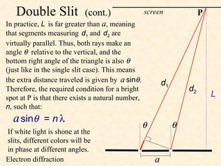
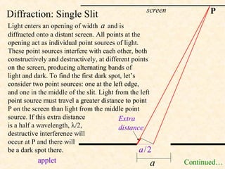
Diffraction: Double Slit
Light passes through two openings, each
of which acts as a point source. Here a is
the distance between the openings rather
than the width of a particular opening. As
before, if d1 - d2 = n λ (a multiple of the
wavelength), light from the two sources
will be in phase and there will a bright d1
spot at P for that wavelength. By the d2
Pythagorean theorem, the exact difference
L
in distance is
d1 - d2 = [ L2 + (x + a / 2)2 ] ½
- [ L2 + (x - a / 2)2 ] ½
Approximation on next slide.
Link 1 Link 2 a x
82. Double Slit (cont.) screen P
In practice, L is far greater than a, meaning
that segments measuring d1 and d2 are
virtually parallel. Thus, both rays make an
angle θ relative to the vertical, and the
bottom right angle of the triangle is also θ
(just like in the single slit case). This means
the extra distance traveled is given by a sinθ. d1
Therefore, the required condition for a bright d2
spot at P is that there exists a natural number, L
n, such that:
a sinθ = n λ θ θ
If white light is shone at the
slits, different colors will be
in phase at different angles.
Electron diffraction a
83. Diffraction Gratings
A different grating has numerous tiny slits, equally spaced. It
separates white light into its component colors just as a double slit
would. When a sinθ = n λ, light of wavelength λ will be reinforced
at an angle of θ. Since different colors have different wavelengths,
different colors will be reinforced at different angles, and a prism-like
spectrum can be produced. Note, though, that prisms separate light via
refraction rather than diffraction. The pic on the left shows red light
shone through a grating. The CD acts as a diffraction grating since the
tracks are very close together (about 625/mm).