This document provides an overview of optics and light, including:
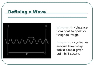
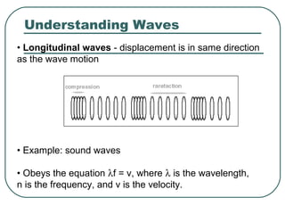
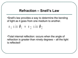
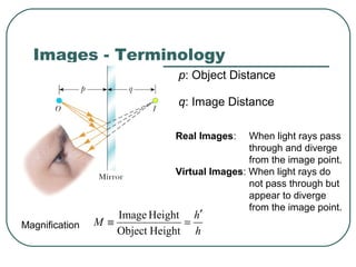
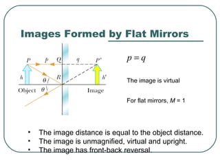
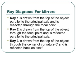
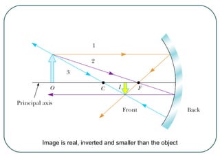
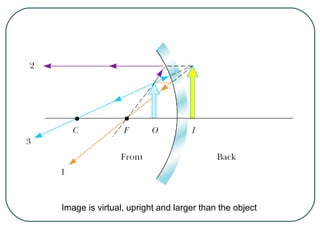
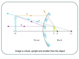
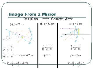
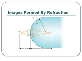
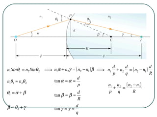
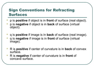
1) It defines key wave properties like wavelength and frequency, and describes longitudinal and transverse waves. 2) It introduces the electromagnetic spectrum and explains how different frequencies are classified. 3) It covers geometric optics concepts such as reflection, refraction, mirrors, lenses and image formation using ray diagrams. Sign conventions are also defined for analyzing optical systems.
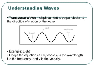
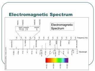
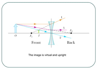
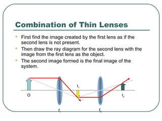


![5 types of social interaction[1].ppt](https://cdn.slidesharecdn.com/ss_thumbnails/5typesofsocialinteraction1-170107094134-thumbnail.jpg?width=640&height=640&fit=bounds)


