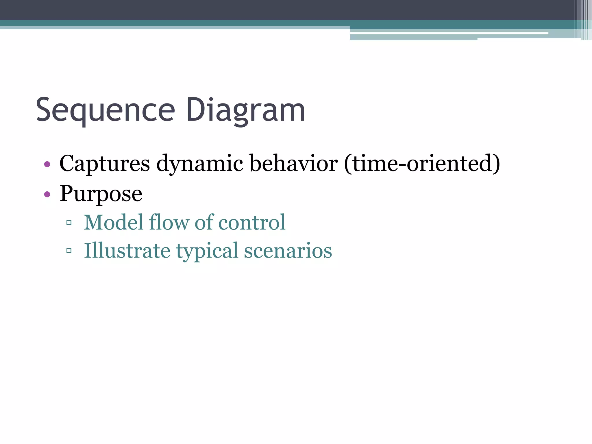
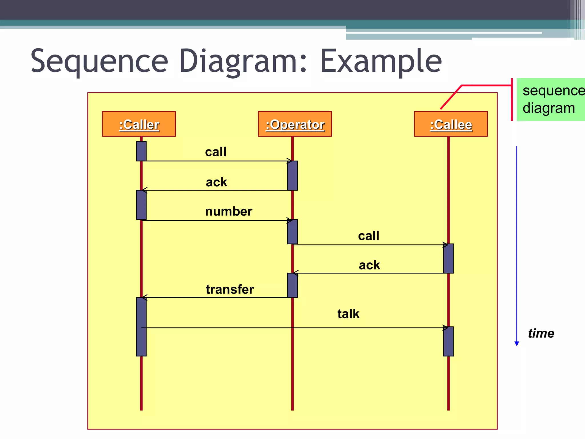
This document discusses sequence diagrams and collaboration diagrams. It explains that sequence diagrams capture dynamic behavior over time by showing messages passing between objects. A sequence diagram displays objects arranged in time sequence and the messages they pass. It also describes the different elements of a sequence diagram like lifelines, messages, and activation bars. The document then introduces collaboration diagrams and notes they show object organization and indicate method call sequence through numbering.
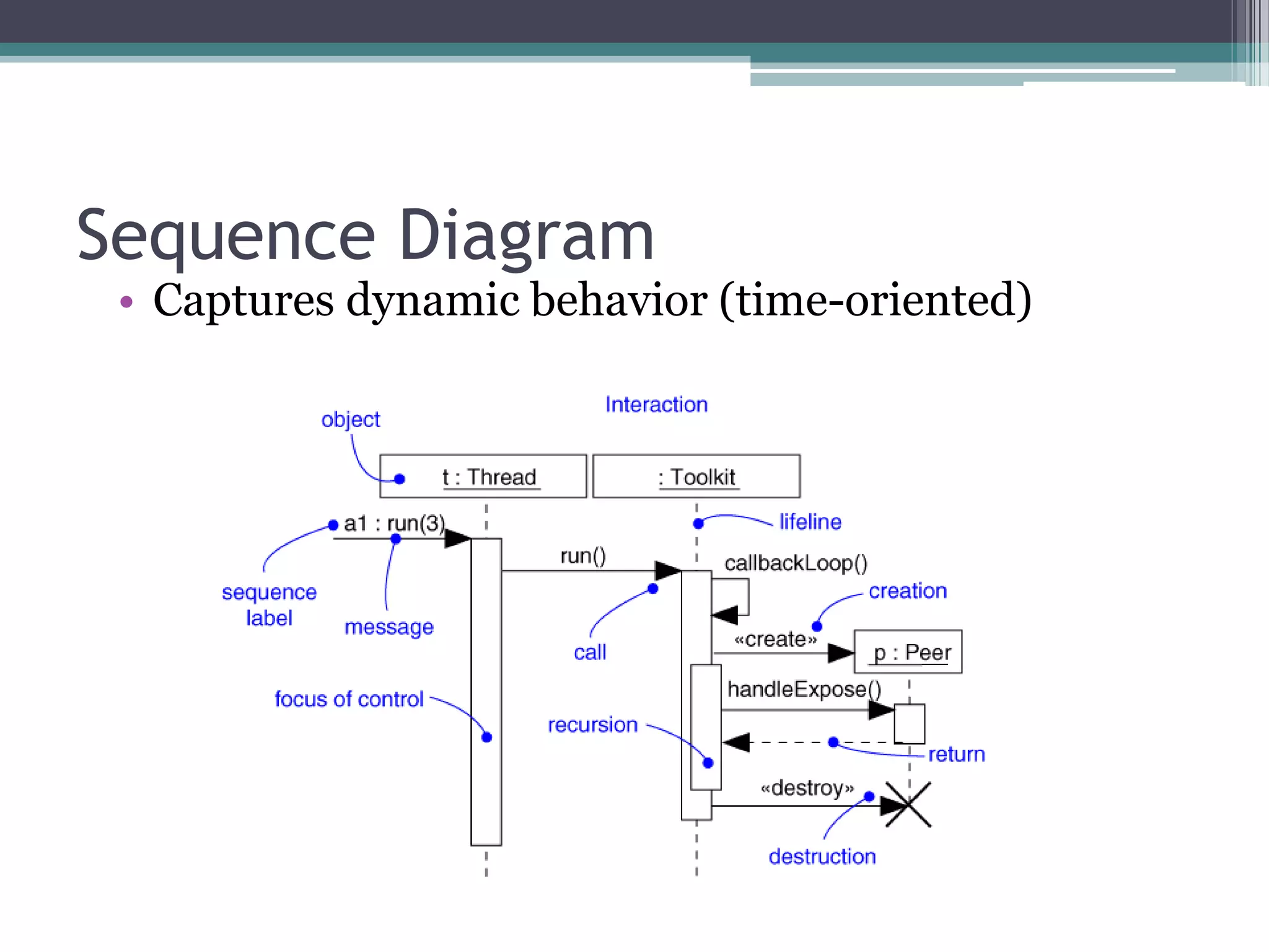

![Sequence Diagram
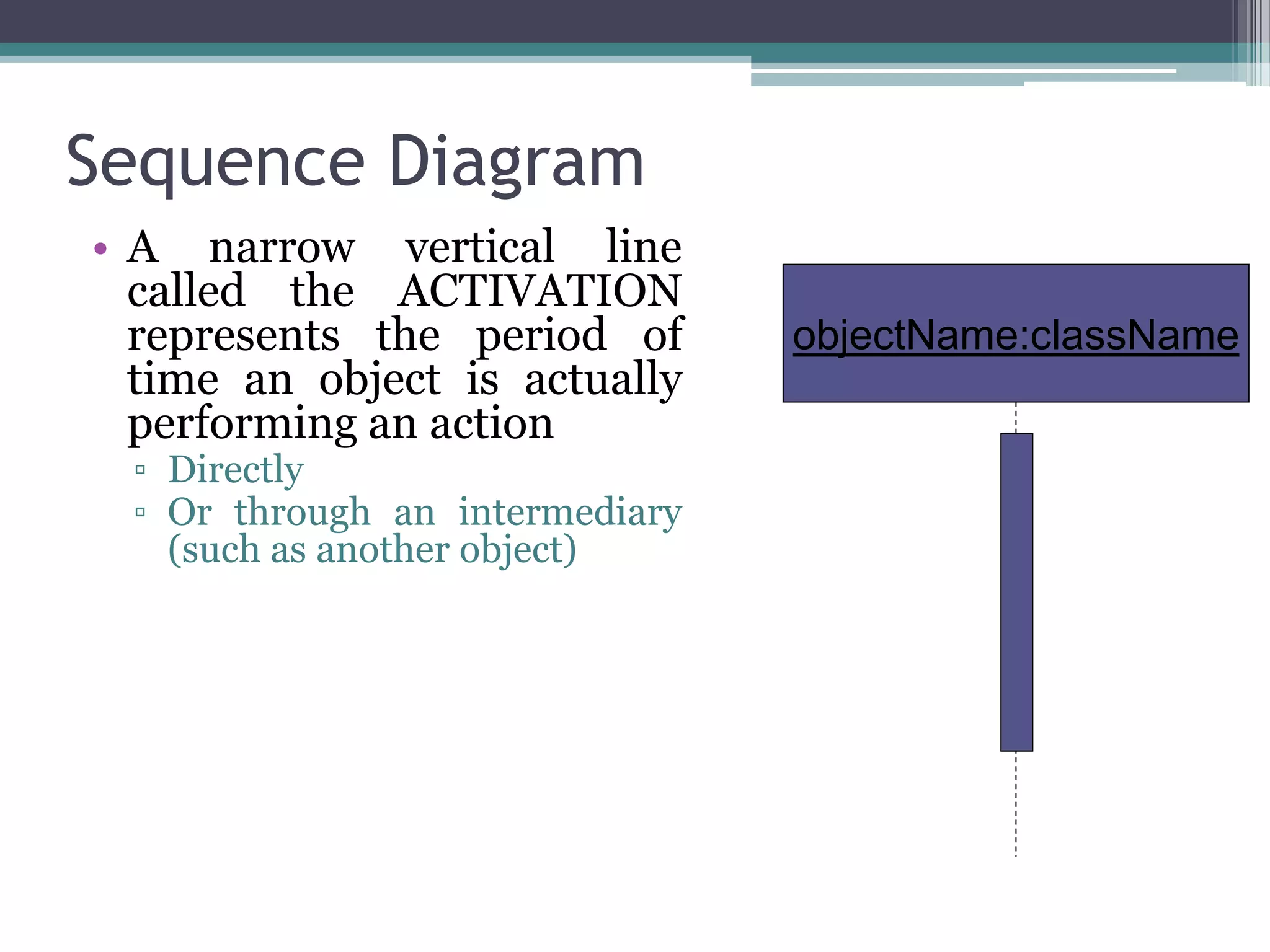
• Objects are shown in rectangles on the top of the
diagrams
• Each rectangle contains
▫ Name (always underlined)
[objects are underlined not class]
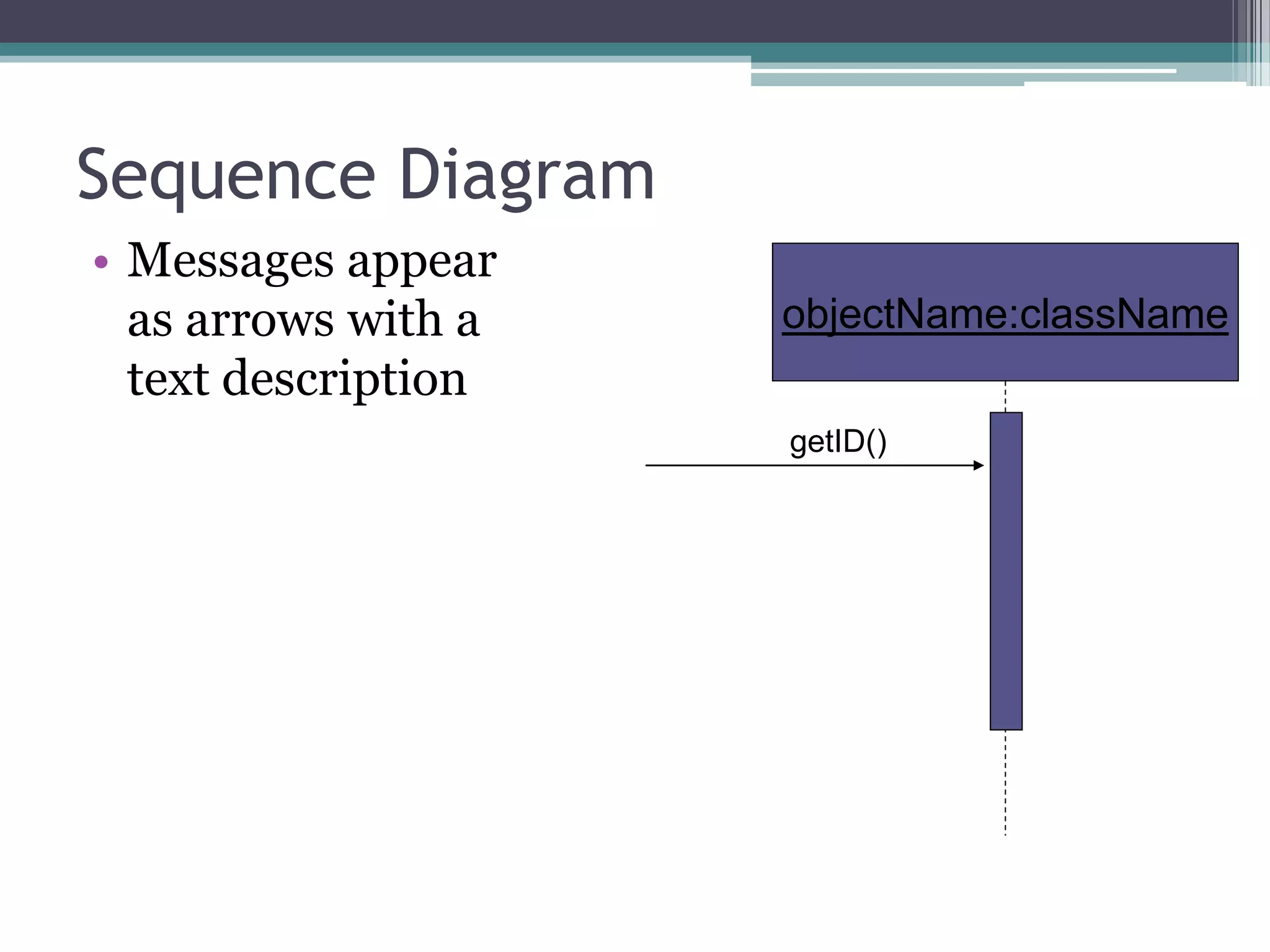
objectName:className](https://image.slidesharecdn.com/ooadsequencediagramcollaborationdiagram-210209195227/75/Ooad-sequence-diagram_collaboration-diagram-8-2048.jpg)