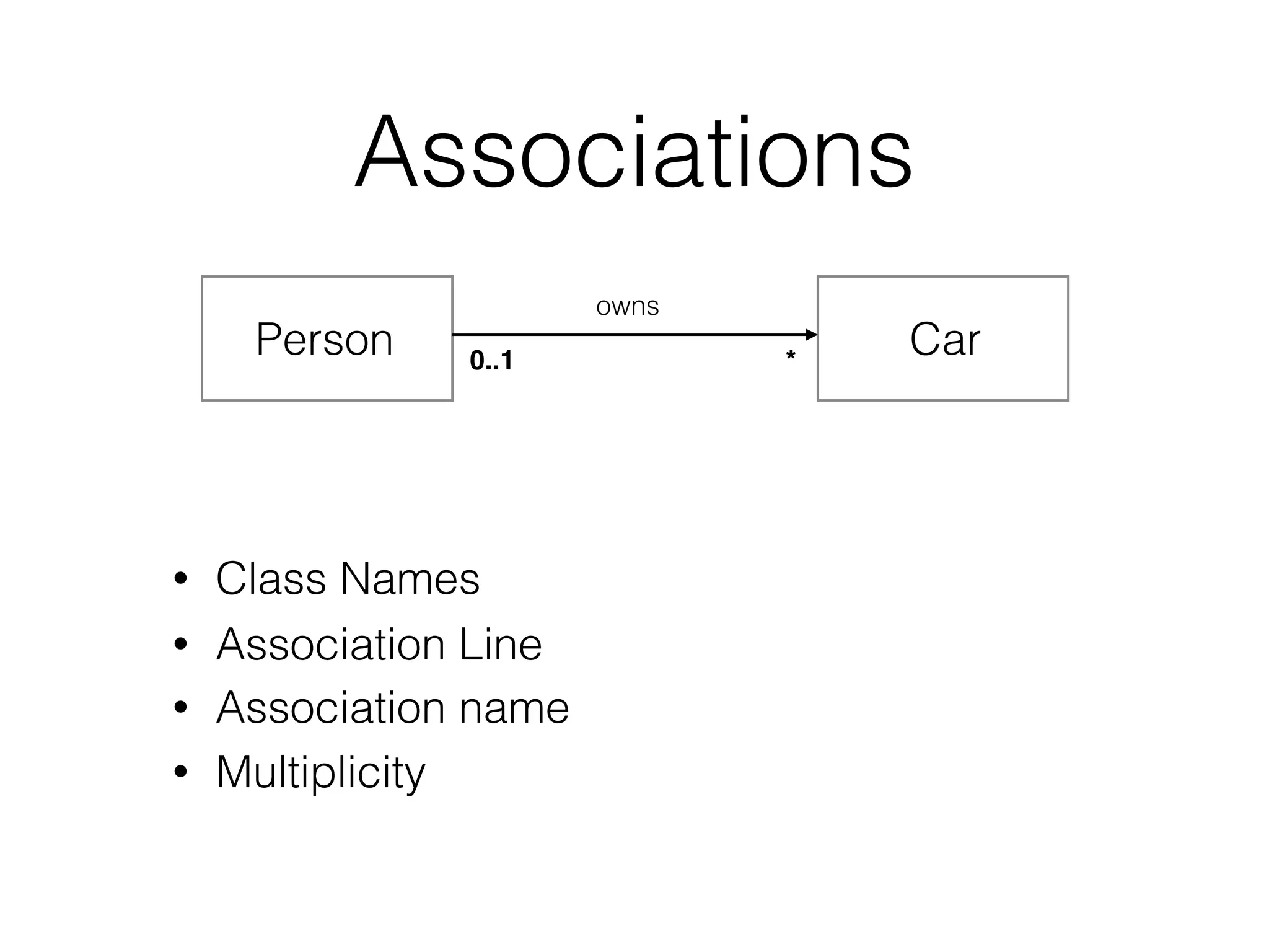
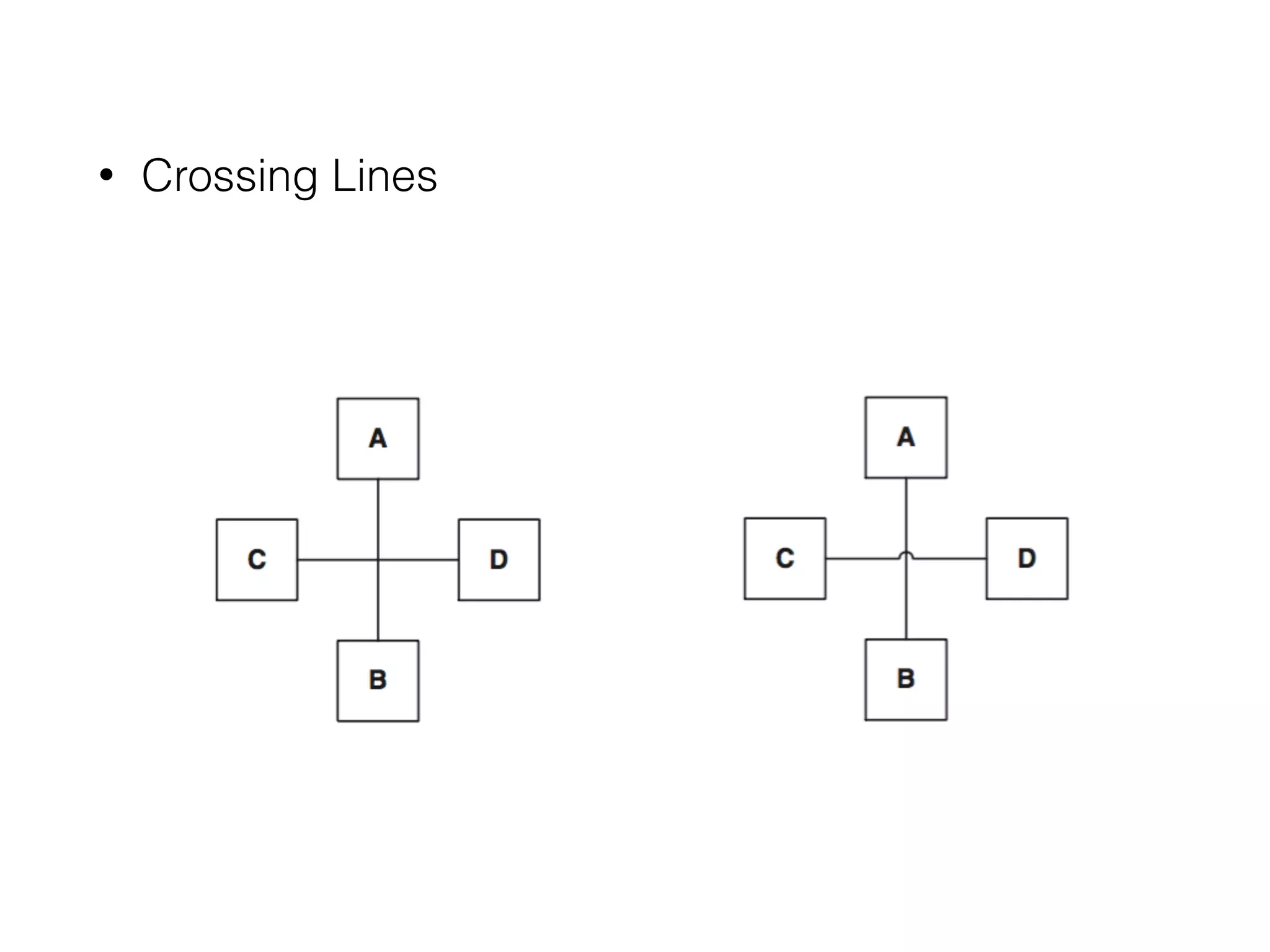
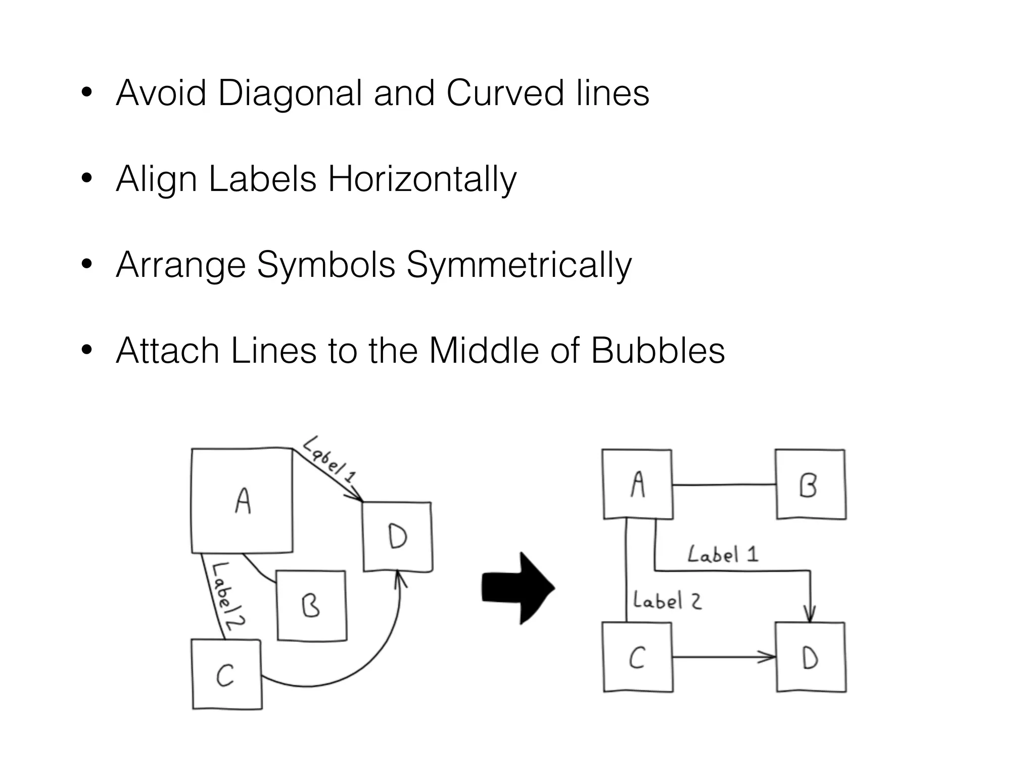
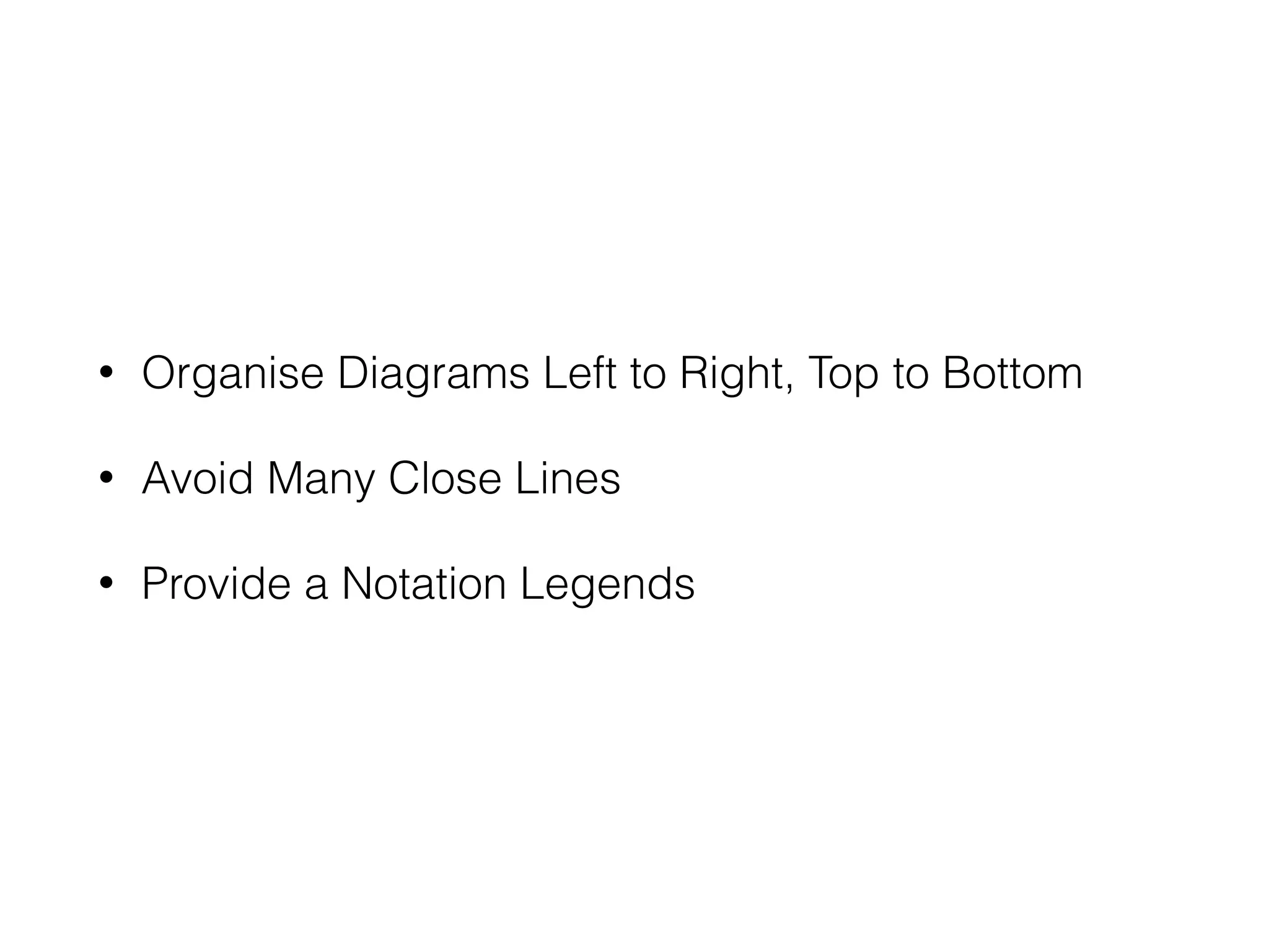
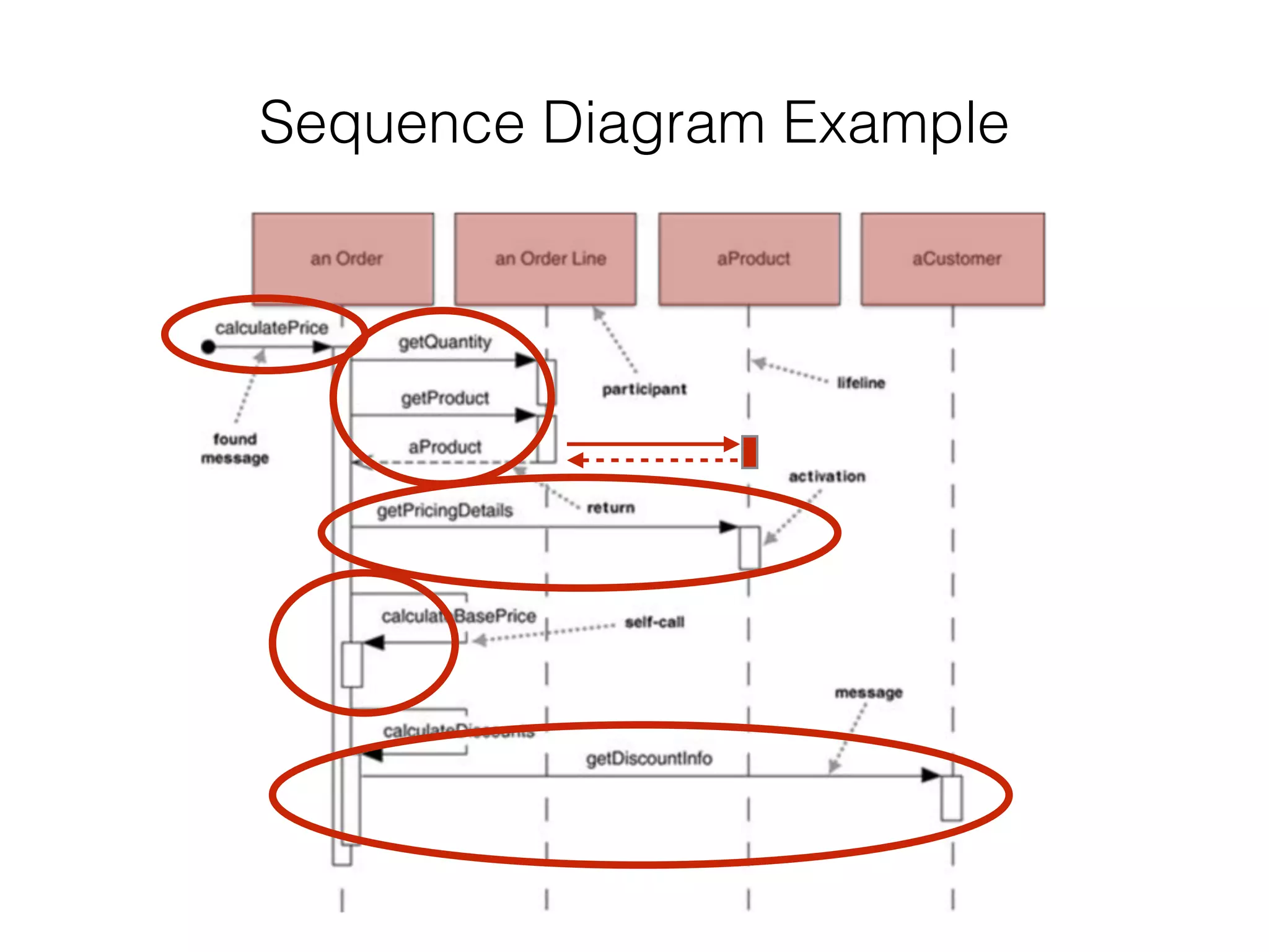
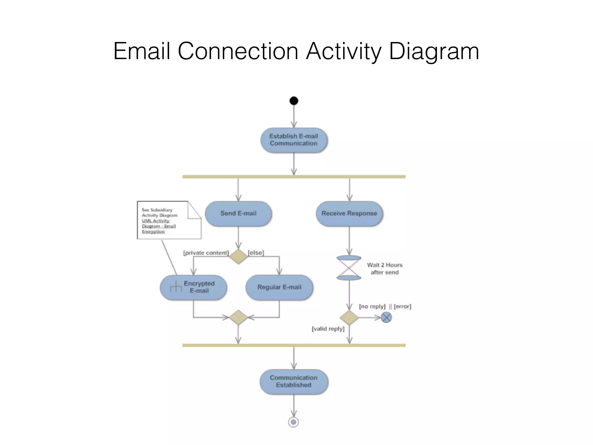
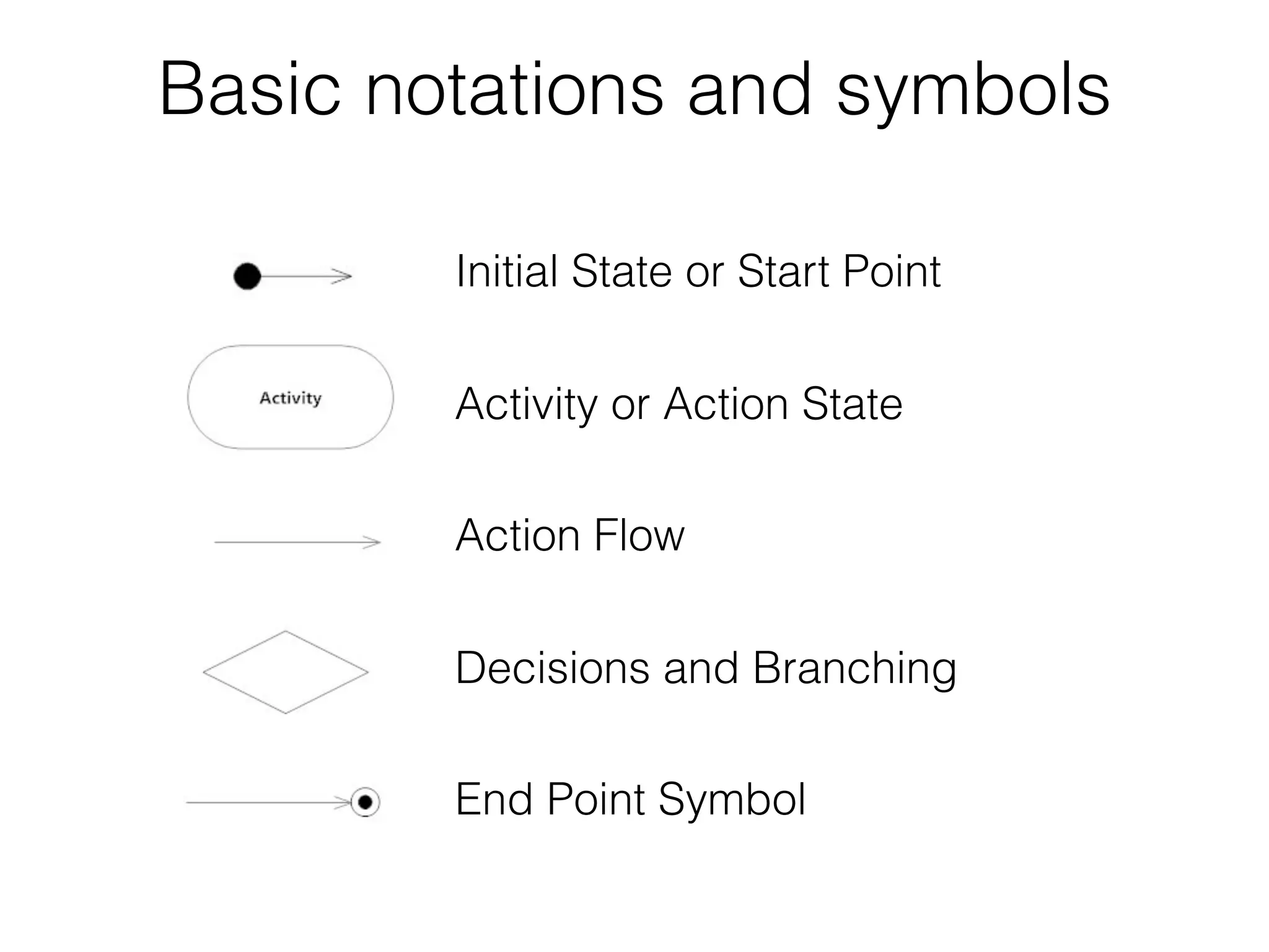
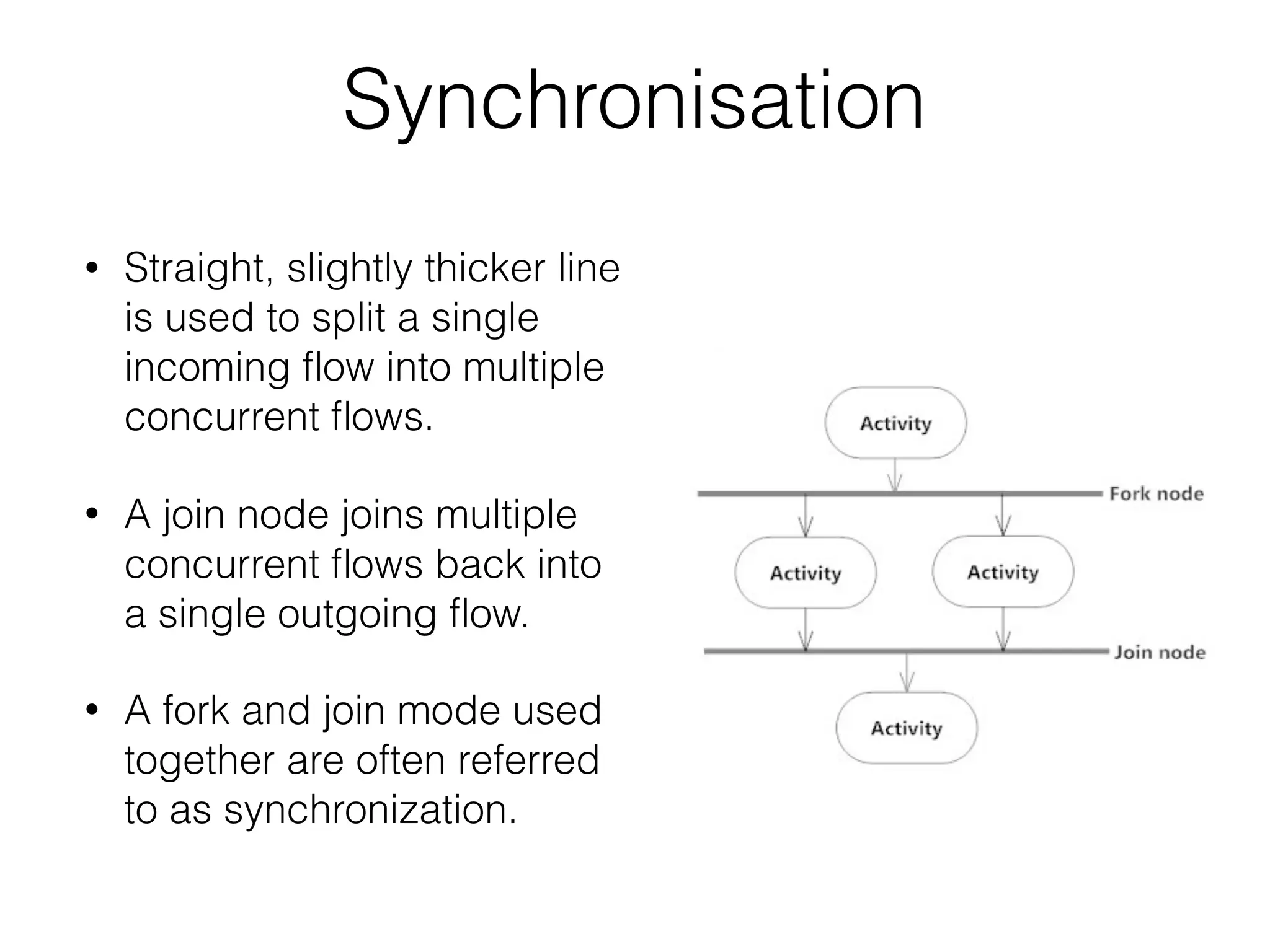
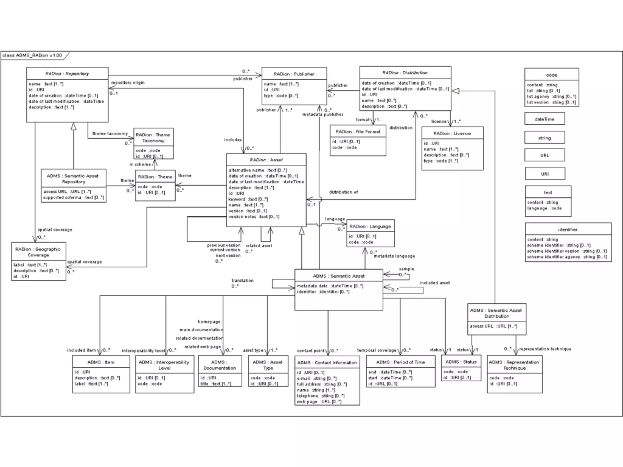
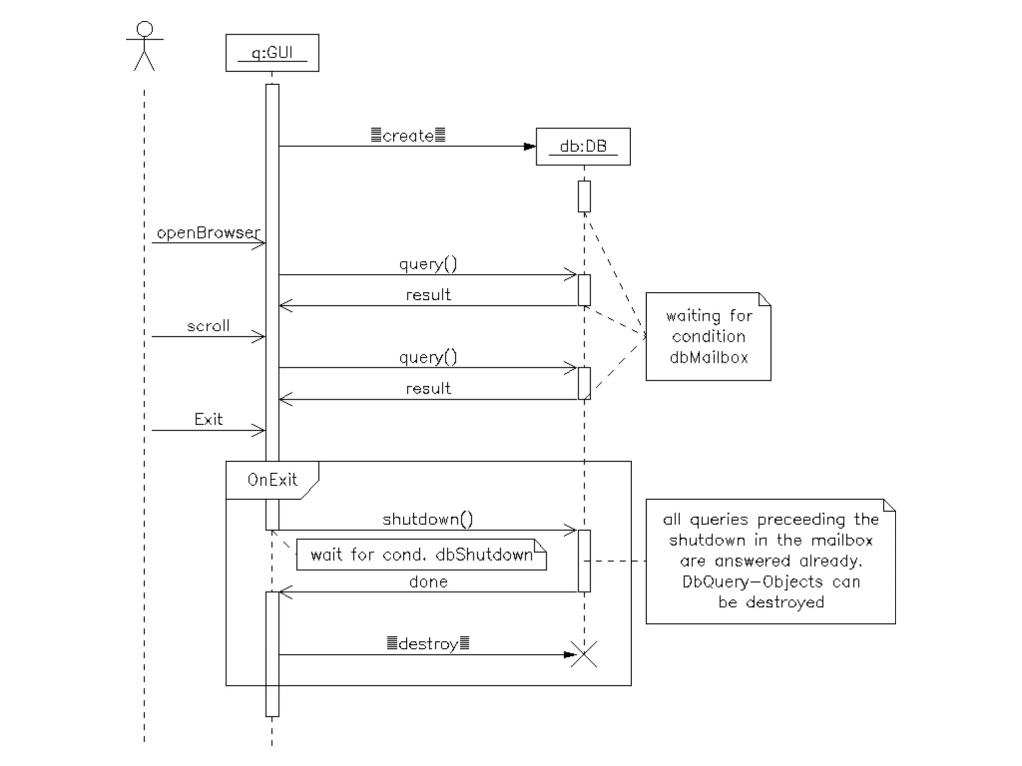
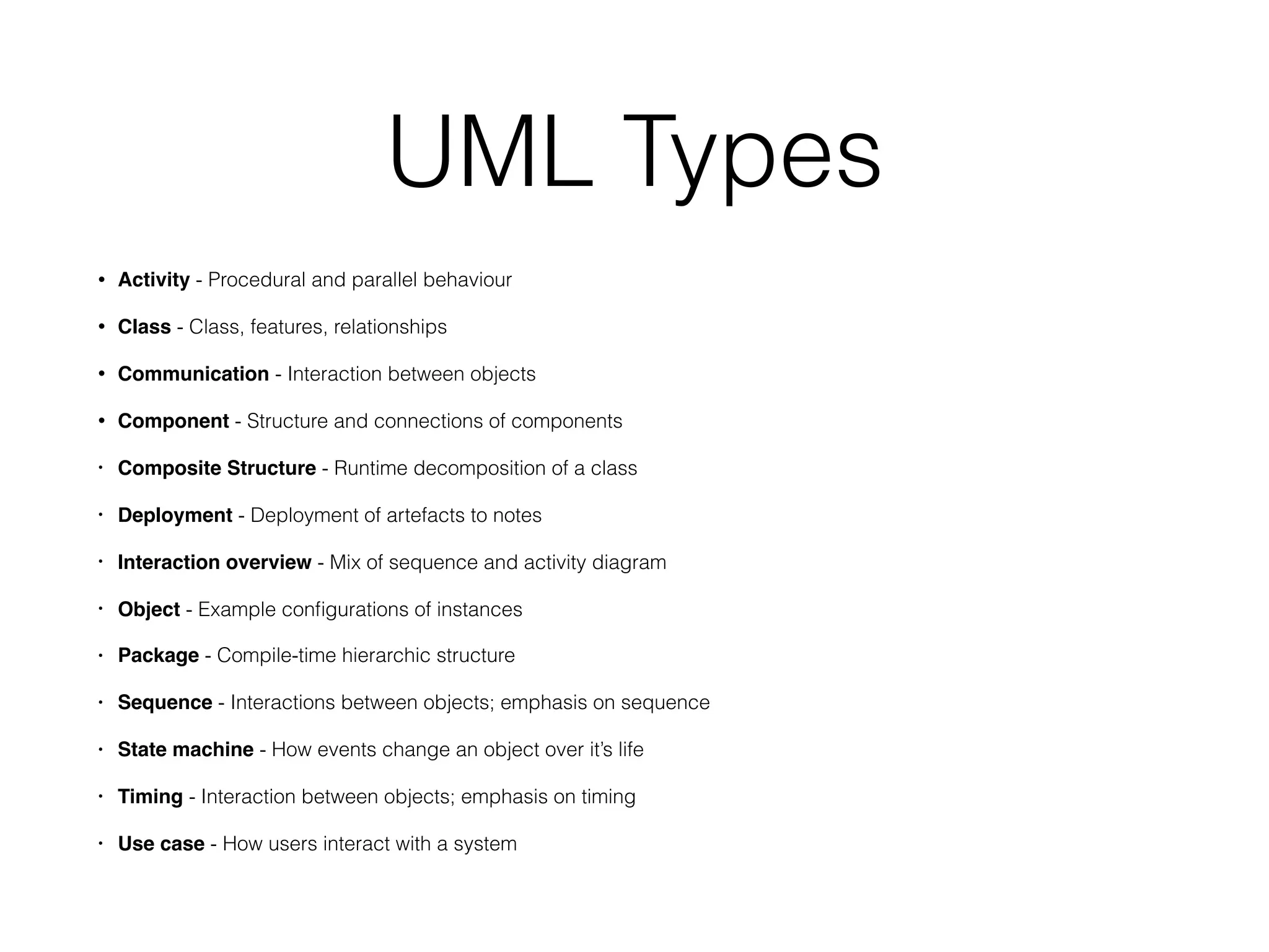
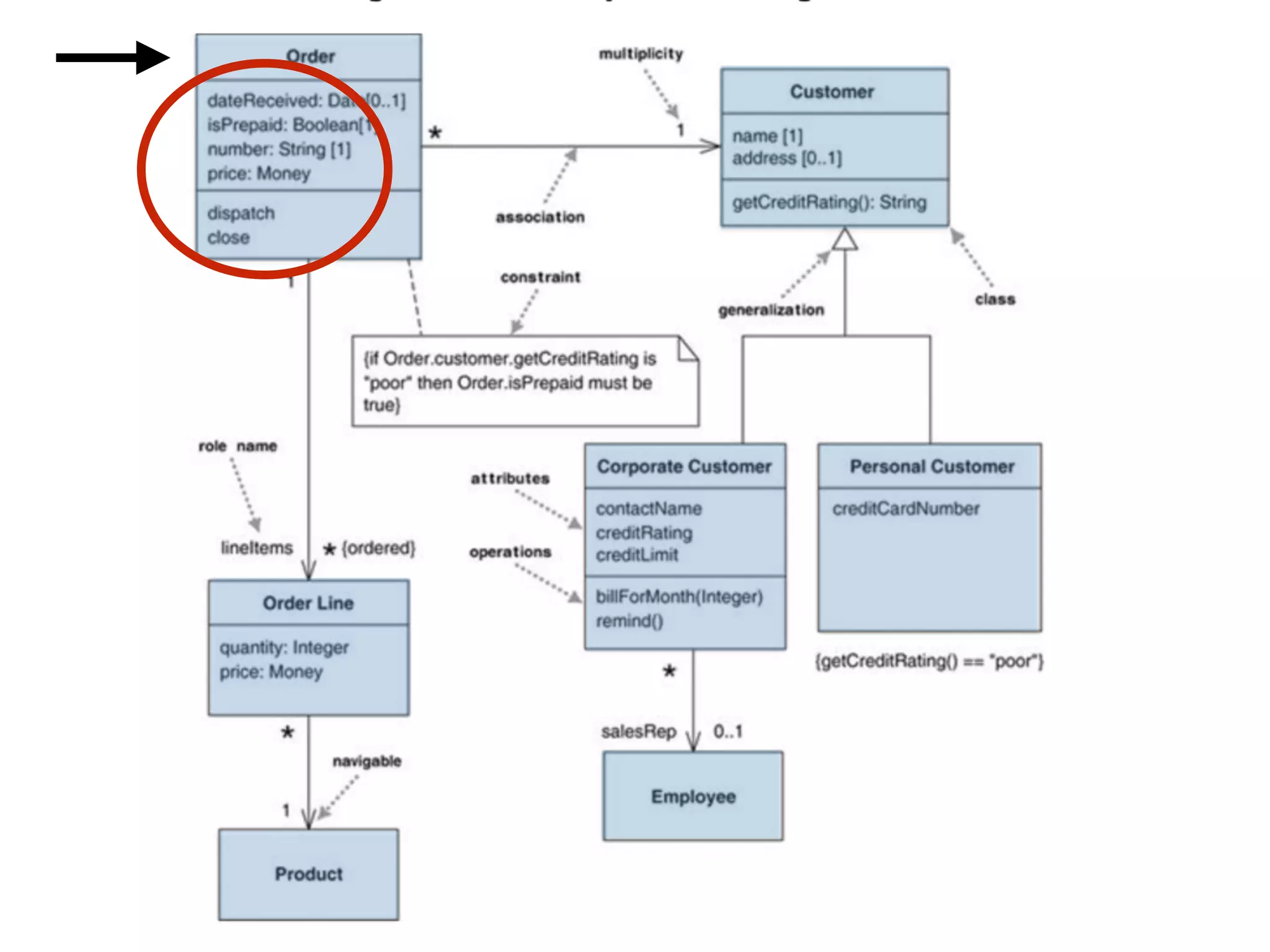
UML 2.0 is a collection of standards and guidelines for creating Unified Modeling Language diagrams to describe and design software systems. It includes several diagram types like class, sequence, activity, and state machine diagrams. Class diagrams describe object relationships, while sequence diagrams show object interactions over time. Activity diagrams display business processes and workflows. General best practices for UML diagrams include avoiding crossed lines, keeping labels horizontal, and organising diagrams systematically.
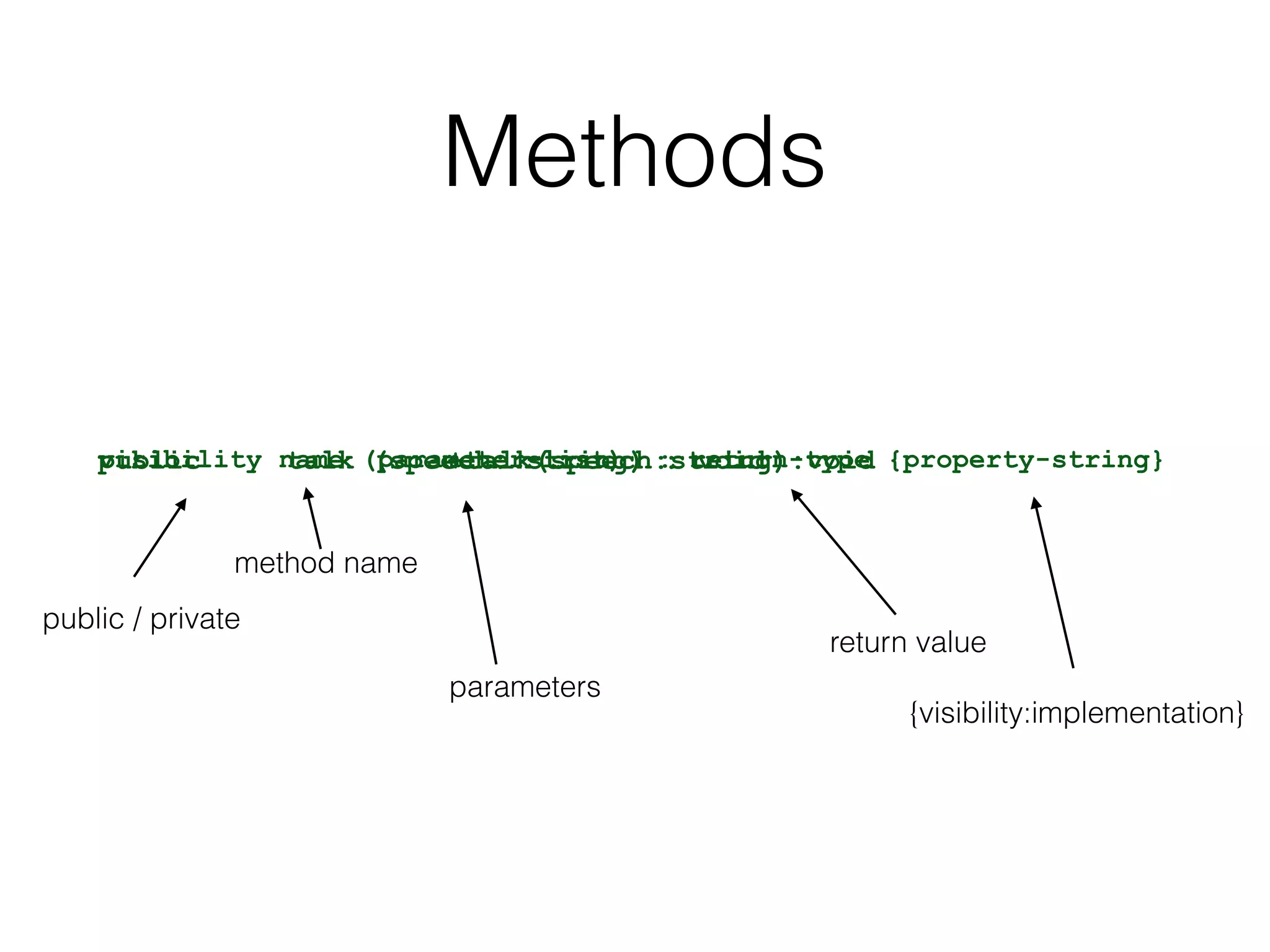
![Attributes
visibility name: type multiplicity = default {property-string}public age: int [1..*] = 15 {readOnly}+ age: int [1..*] = 15 {readOnly}
public / private
attribute name
numeric | boolean | string…
1 | 0..1 | *
default value
{readOnly}](https://image.slidesharecdn.com/87befc63-7366-43f0-9d6a-902fd1ef82b8-151101103413-lva1-app6892/75/UML-10-2048.jpg)