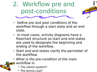
ActivityDiagramActivityDiagram
Preeti Mishra
Course Instructor
Definition
– Activity diagrams represent the dynamics of
the system.
– They are flow charts that are used to show
the workflow of a system.
– They show.
• The flow of control from activity to activity in the
system,
• What activities can be done in parallel.
• Alternate paths through the flow.
– They can show the flow across use cases or
within a use case.
Activity Diagram
• Core symbol is an activity.
• An activity is some task which
needs to be done.
• Each activity can be followed by
another activity (sequencing).
• Triggers from the activity may be
guarded as in state diagrams.
Decision Activities
• Diamond.
• Each trigger coming from it has a guard.
• Synchronisation bar.
• All triggers from this attach to activities
that can occur in parallel, with no specific
sequence, or concurrently.
• The next synchronisation bar closes the
concurrency.
• Iteration is represented by a * on the
trigger.
or
Activity Diagrams for
Use Cases
• They can be used for describing
either
– Use cases or
– Complicated methods
Find
Beverage
Put coffee
in filter
Add water
to reservoir
Drink
Beverage
Pour
coffee
Brew
coffee
Turn on
machine
Put filter
in machine
Get can
of cola
Get
cups
[found coffee]
[no coffee] [no cola]
Assign
to Order
Check line
item
Cancel
Order
Authorise
Payment
Reorder
item
Dispatch
Order
Receive
order
* for each
line
item on
order[faile
d]
[succee
ded]
[in
stock]
[need
to
reorde
r]
[stock
assigned
to all line
items
and payment
authorised]
Activity Diagram
for Receiving an
Order
Activity
Diagram
for
receiving
Supply
Choose outstanding
order items
Assign goods
to order
Add remainder
to stock
Receive
Supply
* for each
chosen order
item
[all
outstanding
order items
filled]
Dispatch
Order
Drawback
• Activity diagrams tell you what is
happening, but not who does what.
• In domain modeling, this diagram type
does not convey which people or
departments are responsible for each
activity.
• In programming, it does not convey
which class is responsible for each
activity.
Swimlanes
• Arrange activity diagrams into vertical
zones separated by dashed lines.
• Each zone represents the
responsibilities of a particular class or
department.
When to Use Activity
Diagrams
• Do use them for
– Analysing Use Cases.
– Understanding workflow across many Use
Cases.
– Dealing with multi-threaded applications.
• Don’t use them
– to see how objects collaborate.
– to see how an object behaves over its
lifetime.
Assign
to Order
Check line
item
Cancel
Order
Authorise
Payment
Choose
outstanding
order items
Assign goods
to order
Reorder
item
Add remainder
to stock
Dispatch
Order
Receive
Supply
Receive
order
Financ
e
Order
Processing
Stock
Manager
* for each
line
item on
order
[faile
d][succee
ded]
* for each
chosen order
item
[in
stock]
[need
to
reorde
r]
[stock
assigned
to all line
items
and payment
authorised]
[all
outstanding
order items
filled]With
Swimlanes
Placing an Activity
diagram
• Where?
– You can attach activity diagrams to most
model elements in the use case or logical
views.
– Activity diagrams cannot reside within the
component view.
• Why?
– Very effective in illustrating the workflow of
various events in a use-case diagram.
– You can use activity diagrams to specify
and define each event in a use-case
diagram.
Creating an activity
diagram
• Modelling a workflow in an activity
diagram
– Identify a workflow objective.
– Decide the pre and post-conditions of the
workflow.
– Define all activities and states.
– Define any objects that are created or
modified.
– Decide on responsibility for performing the
activities.
– Connect all elements on the diagram with
transitions.
– Place decisions on the diagram.
– Evaluate your diagram for concurrent
Identify a workflow
objective.
– "What needs to take place or happen
by the end of the workflow? What
needs to be accomplished?“
– For example, if your activity diagram
models the workflow of ordering a
book from an online bookstore, the
goal of the entire workflow could be
getting the book to the customer.
– What is the goal in the claims
system?
– What are the goals in the tennis club?
2. Workflow pre and
post-conditions
– Define pre and post conditions of the
workflow through a start state and an end
state.
– In most cases, activity diagrams have a
flowchart structure so start and end states
are used to designate the beginning and
ending of the workflow.
– Start and end states clarify the perimeter of
the workflow.
– What is the pre-condition of the main
workflow in
• The claims system?
• The tennis club?
Define activities and
states
• Define and recognize all activities
and states that must take place to
meet your objective. Place and
name them on the activity
diagram in a logical order.
• Are there intermediate states in
the claims / tennis club systems?
Identify persistent
object operations
• Define and diagram any objects
that are created or modified within
your activity diagram.
• Connect the objects and activities
with object flows.
Add swimlanes
• Decide who or what is responsible for
performing the activities and states
through swimlanes.
• Name each swimlane and place the
appropriate activities and states within
each swimlane.
• Identify swimlanes for
– The tennis club workflow
– The claims workflow
Finish diagram
• Connect all elements on the diagram with
transitions.
• Place decisions on the diagram where the
workflow may split into an alternate flow.
– E.g. based on a Boolean expression, the workflow
could branch to a different workflow.
• Evaluate your diagram and see if you have
any concurrent workflows. If so, use
synchronizations to represent forking and
joining.
• Set all actions, triggers and guard conditions
in the specifications of each model element.
Activity diag

Activity diag

  • 1.
  • 2.
    Definition – Activity diagramsrepresent the dynamics of the system. – They are flow charts that are used to show the workflow of a system. – They show. • The flow of control from activity to activity in the system, • What activities can be done in parallel. • Alternate paths through the flow. – They can show the flow across use cases or within a use case.
  • 3.
    Activity Diagram • Coresymbol is an activity. • An activity is some task which needs to be done. • Each activity can be followed by another activity (sequencing). • Triggers from the activity may be guarded as in state diagrams.
  • 4.
    Decision Activities • Diamond. •Each trigger coming from it has a guard. • Synchronisation bar. • All triggers from this attach to activities that can occur in parallel, with no specific sequence, or concurrently. • The next synchronisation bar closes the concurrency. • Iteration is represented by a * on the trigger. or
  • 5.
    Activity Diagrams for UseCases • They can be used for describing either – Use cases or – Complicated methods
  • 6.
    Find Beverage Put coffee in filter Addwater to reservoir Drink Beverage Pour coffee Brew coffee Turn on machine Put filter in machine Get can of cola Get cups [found coffee] [no coffee] [no cola]
  • 7.
    Assign to Order Check line item Cancel Order Authorise Payment Reorder item Dispatch Order Receive order *for each line item on order[faile d] [succee ded] [in stock] [need to reorde r] [stock assigned to all line items and payment authorised] Activity Diagram for Receiving an Order
  • 8.
    Activity Diagram for receiving Supply Choose outstanding order items Assigngoods to order Add remainder to stock Receive Supply * for each chosen order item [all outstanding order items filled] Dispatch Order
  • 9.
    Drawback • Activity diagramstell you what is happening, but not who does what. • In domain modeling, this diagram type does not convey which people or departments are responsible for each activity. • In programming, it does not convey which class is responsible for each activity.
  • 10.
    Swimlanes • Arrange activitydiagrams into vertical zones separated by dashed lines. • Each zone represents the responsibilities of a particular class or department.
  • 11.
    When to UseActivity Diagrams • Do use them for – Analysing Use Cases. – Understanding workflow across many Use Cases. – Dealing with multi-threaded applications. • Don’t use them – to see how objects collaborate. – to see how an object behaves over its lifetime.
  • 12.
    Assign to Order Check line item Cancel Order Authorise Payment Choose outstanding orderitems Assign goods to order Reorder item Add remainder to stock Dispatch Order Receive Supply Receive order Financ e Order Processing Stock Manager * for each line item on order [faile d][succee ded] * for each chosen order item [in stock] [need to reorde r] [stock assigned to all line items and payment authorised] [all outstanding order items filled]With Swimlanes
  • 13.
    Placing an Activity diagram •Where? – You can attach activity diagrams to most model elements in the use case or logical views. – Activity diagrams cannot reside within the component view. • Why? – Very effective in illustrating the workflow of various events in a use-case diagram. – You can use activity diagrams to specify and define each event in a use-case diagram.
  • 14.
    Creating an activity diagram •Modelling a workflow in an activity diagram – Identify a workflow objective. – Decide the pre and post-conditions of the workflow. – Define all activities and states. – Define any objects that are created or modified. – Decide on responsibility for performing the activities. – Connect all elements on the diagram with transitions. – Place decisions on the diagram. – Evaluate your diagram for concurrent
  • 15.
    Identify a workflow objective. –"What needs to take place or happen by the end of the workflow? What needs to be accomplished?“ – For example, if your activity diagram models the workflow of ordering a book from an online bookstore, the goal of the entire workflow could be getting the book to the customer. – What is the goal in the claims system? – What are the goals in the tennis club?
  • 16.
    2. Workflow preand post-conditions – Define pre and post conditions of the workflow through a start state and an end state. – In most cases, activity diagrams have a flowchart structure so start and end states are used to designate the beginning and ending of the workflow. – Start and end states clarify the perimeter of the workflow. – What is the pre-condition of the main workflow in • The claims system? • The tennis club?
  • 17.
    Define activities and states •Define and recognize all activities and states that must take place to meet your objective. Place and name them on the activity diagram in a logical order. • Are there intermediate states in the claims / tennis club systems?
  • 18.
    Identify persistent object operations •Define and diagram any objects that are created or modified within your activity diagram. • Connect the objects and activities with object flows.
  • 19.
    Add swimlanes • Decidewho or what is responsible for performing the activities and states through swimlanes. • Name each swimlane and place the appropriate activities and states within each swimlane. • Identify swimlanes for – The tennis club workflow – The claims workflow
  • 20.
    Finish diagram • Connectall elements on the diagram with transitions. • Place decisions on the diagram where the workflow may split into an alternate flow. – E.g. based on a Boolean expression, the workflow could branch to a different workflow. • Evaluate your diagram and see if you have any concurrent workflows. If so, use synchronizations to represent forking and joining. • Set all actions, triggers and guard conditions in the specifications of each model element.