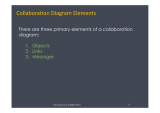
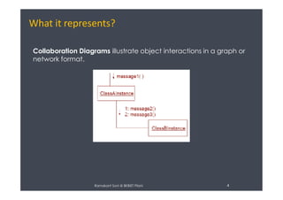
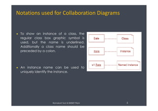
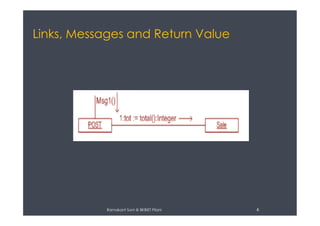
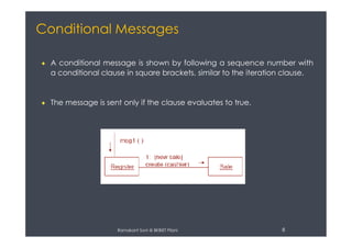
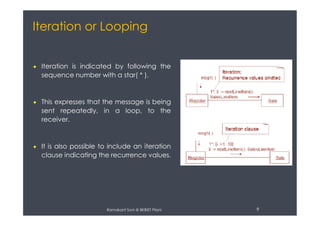
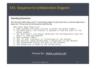
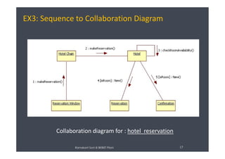
The document discusses collaboration diagrams, which capture the dynamic behavior of objects collaborating to perform tasks. Collaboration diagrams illustrate object interactions through messages in a graph format. They show objects, links between objects, and messages to model control flow and coordination. Notations are used to represent classes, instances, links, messages, return values, self-messages, conditional messages, iteration, and collections of objects. Examples of converting sequence diagrams to collaboration diagrams for making a phone call, changing flight itineraries, and making a hotel reservation are provided.
This Presentation contains all the topics in design concept of software engineering. This is much more helpful in designing new product. You have to consider some of the design concepts that are given in the ppt
Unified Modeling Language (UML) is a modeling language, used for design. Designed based on OMG Standard, Object this helps to express and design documents, software. This is particularly useful for OO design. Here is a brief tutorial that talks about UML usage.
This slide give the basic introduction about UML diagram and it's types, and brief intro about Activity Diagram, use of activity diagram in object oriented programming language..
UML stands for Unified Modelling Language.
UML is a standard language for specifying, visualizing, constructing, and documenting a system in which software represents the most significant part.
UML is different from the other common programming languages like C++, Java, COBOL etc.
UML is a pictorial language used to make software blue prints.
UML can serve as a central notation for software development process. Using UML helps project teams communicate, explore potential designs, and validate the architectural designs of software.
UML diagrams are made using notation of things and relationships.
The building blocks of UML can be defined as:
Things
Relationships
Diagrams
Things: Things are the most important building blocks of UML. Things can be:
Structural
Behavioral
Grouping
Annotational
The Structural things define the static part of the model. They represent physical and conceptual elements. Following are the brief descriptions of the structural things.
Class: Class represents set of objects having similar responsibilities.
Interface: Interface defines a set of operations which specify the responsibility of a class.
Collaboration: Collaboration defines interaction between elements.
Use case: Use case represents a set of actions performed by a system for a specific goal.
Component: Component describes physical part of a system.
Node: A node can be defined as a physical element that exists at run time.
A behavioral thing consists of the dynamic parts of UML models. Following are the behavioral things:
Interaction: Interaction is defined as a behavior that consists of a group of messages exchanged among elements to accomplish a specific task.
State machine: State machine is useful when the state of an object in its life cycle is important. It defines the sequence of states an object goes through in response to events. Events are external factors responsible for state change.
The objective is to explain how a software design may be represented as a set of interacting objects that manage their own state and operations and to introduce various models that describe an object-oriented design.
Master sequence diagrams with this sequence diagram guide. It describes everything you need to know on sequence diagram notations, best practices as well as common mistakes. It also explains how to draw a sequence diagram step by step. Plus it offers Creately sequence diagram templates you can click and edit right away.
OOAD Part A Question with answer and Part B & C questions.
References :
1) Previous University Questions.
2) Applying UML and Patterns: An Introduction to Object-Oriented Analysis and Design and Iterative Development by Craig Larman.
3) Google search engine for text and images.
This presentation contain almost everything about the algorithms- its definition, designing, complexity analysis, running time calculations, common sorting and searching algorithms with their running time and examples.
Blood Bank Management Information System [Web-Url: http://infobloodbank.somee...Showrav Mazumder
Software development project presentation on Blood Bank Management Information System. It was my first own project with asp.net.
Web-Url: http://infobloodbank.somee.com/
The Three Speeds are a simple and effective model to think about collaboration strategy, adoption and tool selection for companies.
From a talk I gave at MEX 2013 (London).
Here one of the examples I gave, about Atos switching away from email:
http://www.ft.com/cms/s/0/11384220-8761-11e2-bde6-00144feabdc0.html#axzz2fv5QOuzH
FRACTAL ANALYSIS OF GOOD PROGRAMMING STYLEcscpconf
This paper studies a new, quantitative approach using fractal geometry to analyze basic tenets of good programming style. Experiments on C source of the GNU/Linux Core Utilities, a
collection of 114 programs or approximately 70,000 lines of code, show systematic changes in style are correlated with statistically significant changes in fractal dimension (P≤0.0009). The data further show positive but weak correlation between lines of code and fractal dimension (r=0.0878). These results suggest the fractal dimension is a reliable metric of changes that
affect good style, the knowledge of which may be useful for maintaining a code base.
This paper studies a new, quantitative approach using fractal geometry to analyse basic tenets
of good programming style. Experiments on C source of the GNU/Linux Core Utilities, a
collection of 114 programs or approximately 70,000 lines of code, show systematic changes in
style are correlated with statistically significant changes in fractal dimension (P≤0.0009). The
data further show positive but weak correlation between lines of code and fractal dimension
(r=0.0878). These results suggest the fractal dimension is a reliable metric of changes that
affect good style, the knowledge of which may be useful for maintaining a code base.
Entity Linking, the task of mapping ambiguous Named Entities to unique identifiers in a knowledge base, is a cornerstone of multiple Information Retrieval and Text Analysis pipelines. So far, no single entity linking algorithm has been able to offer the accuracy and scalability required to deal with the ever-increasing amount of data in the web and become a de-facto standard. In this work, we propose a framework for entity linking that
leverages graph embeddings to perform collective disambiguation. This framework support pluggable algorithms for generating embeddings and ranking the candidates. Moreover, we use our framework to evaluate a reference pipeline that uses DBpedia as knowledge base and leverages specific algorithms for fast candidate search and high-performance state-space search optimization. Compared to existing solutions, our pipeline offers state-of-the-art accuracy on a variety of datasets without any supervised training and provides real-time execution even when processing documents with dozens of Named Entities. Additionally, the flexibility of our framework allows adapting adapt to a multitude of scenarios by balancing accuracy and execution time.
Role of Data Cleaning in Data WarehouseRamakant Soni
Data cleaning, also called data cleansing or scrubbing, deals with detecting and removing errors and inconsistencies from data in order to improve the quality of data.
This Presentation is about NoSQL which means Not Only SQL. This presentation covers the aspects of using NoSQL for Big Data and the differences from RDBMS.
Explore the innovative world of trenchless pipe repair with our comprehensive guide, "The Benefits and Techniques of Trenchless Pipe Repair." This document delves into the modern methods of repairing underground pipes without the need for extensive excavation, highlighting the numerous advantages and the latest techniques used in the industry.
Learn about the cost savings, reduced environmental impact, and minimal disruption associated with trenchless technology. Discover detailed explanations of popular techniques such as pipe bursting, cured-in-place pipe (CIPP) lining, and directional drilling. Understand how these methods can be applied to various types of infrastructure, from residential plumbing to large-scale municipal systems.
Ideal for homeowners, contractors, engineers, and anyone interested in modern plumbing solutions, this guide provides valuable insights into why trenchless pipe repair is becoming the preferred choice for pipe rehabilitation. Stay informed about the latest advancements and best practices in the field.
Quality defects in TMT Bars, Possible causes and Potential Solutions.PrashantGoswami42
Maintaining high-quality standards in the production of TMT bars is crucial for ensuring structural integrity in construction. Addressing common defects through careful monitoring, standardized processes, and advanced technology can significantly improve the quality of TMT bars. Continuous training and adherence to quality control measures will also play a pivotal role in minimizing these defects.
Industrial Training at Shahjalal Fertilizer Company Limited (SFCL)MdTanvirMahtab2
This presentation is about the working procedure of Shahjalal Fertilizer Company Limited (SFCL). A Govt. owned Company of Bangladesh Chemical Industries Corporation under Ministry of Industries.
Vaccine management system project report documentation..pdfKamal Acharya
The Division of Vaccine and Immunization is facing increasing difficulty monitoring vaccines and other commodities distribution once they have been distributed from the national stores. With the introduction of new vaccines, more challenges have been anticipated with this additions posing serious threat to the already over strained vaccine supply chain system in Kenya.
Automobile Management System Project Report.pdfKamal Acharya
The proposed project is developed to manage the automobile in the automobile dealer company. The main module in this project is login, automobile management, customer management, sales, complaints and reports. The first module is the login. The automobile showroom owner should login to the project for usage. The username and password are verified and if it is correct, next form opens. If the username and password are not correct, it shows the error message.
When a customer search for a automobile, if the automobile is available, they will be taken to a page that shows the details of the automobile including automobile name, automobile ID, quantity, price etc. “Automobile Management System” is useful for maintaining automobiles, customers effectively and hence helps for establishing good relation between customer and automobile organization. It contains various customized modules for effectively maintaining automobiles and stock information accurately and safely.
When the automobile is sold to the customer, stock will be reduced automatically. When a new purchase is made, stock will be increased automatically. While selecting automobiles for sale, the proposed software will automatically check for total number of available stock of that particular item, if the total stock of that particular item is less than 5, software will notify the user to purchase the particular item.
Also when the user tries to sale items which are not in stock, the system will prompt the user that the stock is not enough. Customers of this system can search for a automobile; can purchase a automobile easily by selecting fast. On the other hand the stock of automobiles can be maintained perfectly by the automobile shop manager overcoming the drawbacks of existing system.
Courier management system project report.pdfKamal Acharya
It is now-a-days very important for the people to send or receive articles like imported furniture, electronic items, gifts, business goods and the like. People depend vastly on different transport systems which mostly use the manual way of receiving and delivering the articles. There is no way to track the articles till they are received and there is no way to let the customer know what happened in transit, once he booked some articles. In such a situation, we need a system which completely computerizes the cargo activities including time to time tracking of the articles sent. This need is fulfilled by Courier Management System software which is online software for the cargo management people that enables them to receive the goods from a source and send them to a required destination and track their status from time to time.
Welcome to WIPAC Monthly the magazine brought to you by the LinkedIn Group Water Industry Process Automation & Control.
In this month's edition, along with this month's industry news to celebrate the 13 years since the group was created we have articles including
A case study of the used of Advanced Process Control at the Wastewater Treatment works at Lleida in Spain
A look back on an article on smart wastewater networks in order to see how the industry has measured up in the interim around the adoption of Digital Transformation in the Water Industry.
CFD Simulation of By-pass Flow in a HRSG module by R&R Consult.pptxR&R Consult
CFD analysis is incredibly effective at solving mysteries and improving the performance of complex systems!
Here's a great example: At a large natural gas-fired power plant, where they use waste heat to generate steam and energy, they were puzzled that their boiler wasn't producing as much steam as expected.
R&R and Tetra Engineering Group Inc. were asked to solve the issue with reduced steam production.
An inspection had shown that a significant amount of hot flue gas was bypassing the boiler tubes, where the heat was supposed to be transferred.
R&R Consult conducted a CFD analysis, which revealed that 6.3% of the flue gas was bypassing the boiler tubes without transferring heat. The analysis also showed that the flue gas was instead being directed along the sides of the boiler and between the modules that were supposed to capture the heat. This was the cause of the reduced performance.
Based on our results, Tetra Engineering installed covering plates to reduce the bypass flow. This improved the boiler's performance and increased electricity production.
It is always satisfying when we can help solve complex challenges like this. Do your systems also need a check-up or optimization? Give us a call!
Work done in cooperation with James Malloy and David Moelling from Tetra Engineering.
More examples of our work https://www.r-r-consult.dk/en/cases-en/
CFD Simulation of By-pass Flow in a HRSG module by R&R Consult.pptx
Collaboration diagram- UML diagram
1. Duration: 3hrs
1
Ramakant Soni
Assistant Professor
Dept. of Computer Science
B K Birla Institute of Engineering & Technology, Pilani, India
Ramakant Soni @ BKBIET Pilani
2. Collaboration Diagram Definition
Collaboration Diagrams captures dynamic behavior of
the objects in the system (message-oriented).
They are very useful for visualizing the relationship
between objects collaborating to perform a particular
task.
Ramakant Soni @ BKBIET Pilani 2
Their purpose is to:
Model flow of control
Illustrate coordination of object structure and control
3. Collaboration Diagram Elements
There are three primary elements of a collaboration
diagram:
1. Objects
2. Links
3. Messages
Ramakant Soni @ BKBIET Pilani 3
3. Messages
4. What it represents?
Collaboration Diagrams illustrate object interactions in a graph or
network format.
Ramakant Soni @ BKBIET Pilani 4
5. Notations used for Collaboration Diagrams
To show an instance of a class, the
regular class box graphic symbol is
used, but the name is underlined.
Additionally a class name should be
preceded by a colon.
Ramakant Soni @ BKBIET Pilani 5
An instance name can be used to
uniquely identify the instance.
7. “Self” Messages
A message can be sent from an object to itself.
This is illustrated by a link to itself, with messages flowing along the link.
Ramakant Soni @ BKBIET Pilani 7
8. Conditional Messages
A conditional message is shown by following a sequence number with
a conditional clause in square brackets, similar to the iteration clause.
The message is sent only if the clause evaluates to true.
Ramakant Soni @ BKBIET Pilani 8
9. Iteration or Looping
Iteration is indicated by following the
sequence number with a star( * ).
This expresses that the message is being
sent repeatedly, in a loop, to the
Ramakant Soni @ BKBIET Pilani 9
sent repeatedly, in a loop, to the
receiver.
It is also possible to include an iteration
clause indicating the recurrence values.