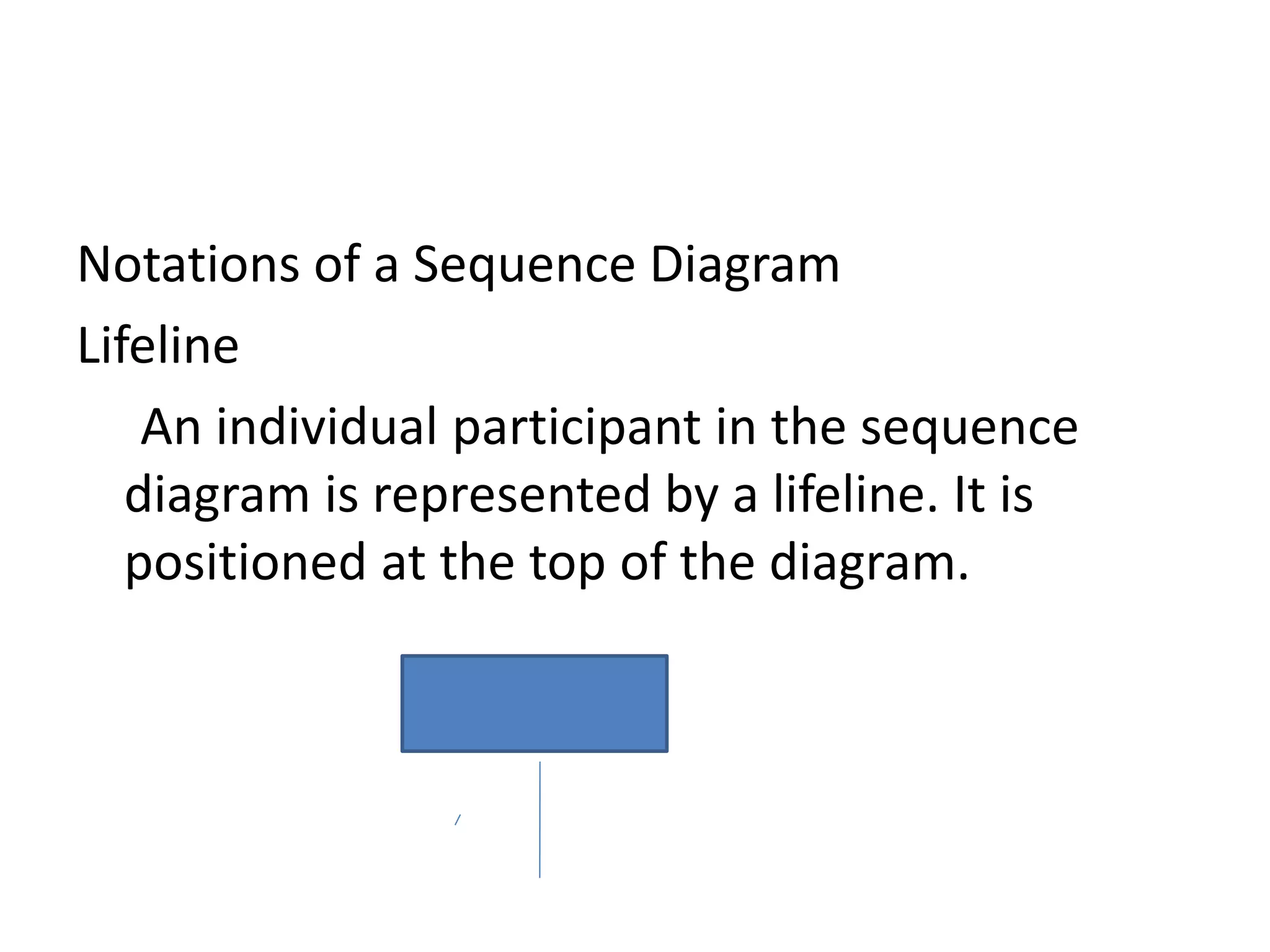
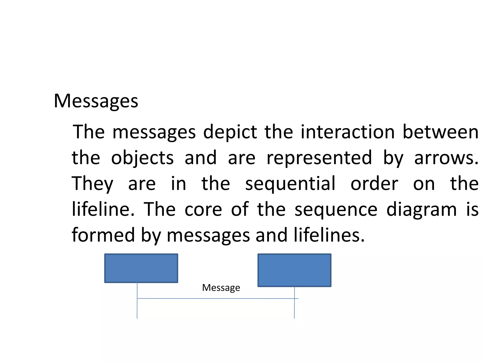
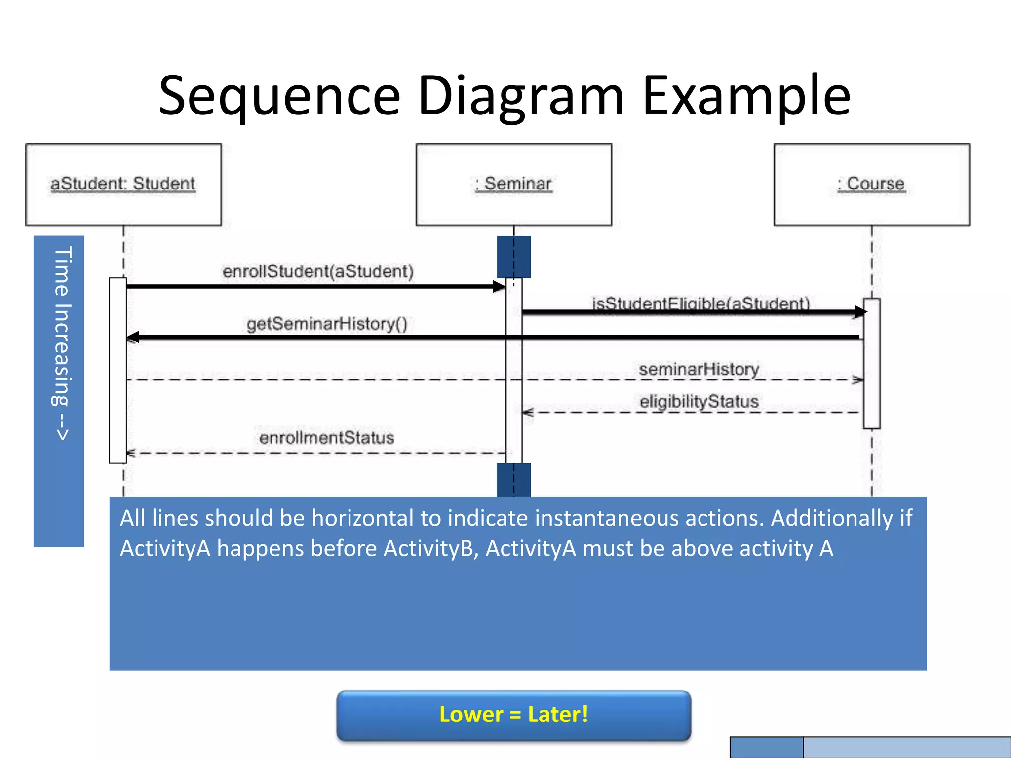
CS8592 OOAD
Dynamic Diagrams
Dr.P.Mayil Vel Kumar
HOD/CSE
Karpagam Institute of Technology
UML interaction diagrams
Interaction diagrams is to visualize the
interactive behavior of the system.
It consist two types :
i. Sequence Diagram
ii. Collaboration Diagram
Sequence Diagram
The sequence diagram represents the flow
of messages in the system and is also termed
as an event diagram. It helps in envisioning
several dynamic scenarios.
Notations of a Sequence Diagram
Lifeline
An individual participant in the sequence
diagram is represented by a lifeline. It is
positioned at the top of the diagram.
Messages
The messages depict the interaction between
the objects and are represented by arrows.
They are in the sequential order on the
lifeline. The core of the sequence diagram is
formed by messages and lifelines.
Message
Coming up: Components
Sequence Diagram Example
Time
Increasing
-->
All lines should be horizontal to indicate instantaneous actions. Additionally if
ActivityA happens before ActivityB, ActivityA must be above activity A
Lower = Later!
Collaboration Diagram
The collaboration diagram is used to show the
relationship between the objects in a system.
Both the sequence and the collaboration
diagrams represent the same information but
differently. Instead of showing the flow of
messages, it depicts the architecture of the
object residing in the system as it is based on
object-oriented programming.
Collaboration Diagram
Notations of a Collaboration Diagram
Following are the components of a component
diagram that are enlisted below:
Objects: The representation of an object is done
by an object symbol with its name and class
underlined, separated by a colon.
Collaboration Diagram
Links: The link is an instance of association, which associates the
objects and actors. It portrays a relationship between the
objects through which the messages are sent. It is
represented by a solid line. The link helps an object to
connect with or navigate to another object, such that the
message flows are attached to links.
Messages: It is a communication between objects which carries
information and includes a sequence number, so that the
activity may take place. It is represented by a labeled arrow,
which is placed near a link. The messages are sent from the
sender to the receiver, and the direction must be navigable in
that particular direction. The receiver must understand the
message.
Collaboration Diagrams
Conditional Paths – mutually exclusive messages
:ClassA
:ClassB
:ClassC :ClassD
msg1( )
1a: [test] msg2( )
1b: [not test] msg4( )
1b.1: msg5( )
1a.1: msg3( )
guard – if true send msg
A state diagram is used to represent the condition of the
system or part of the system at finite instances of time. It’s
a behavioral diagram and it represents the behavior using
finite state transitions.
Cs8592 ooad unit 3
Cs8592 ooad unit 3
Cs8592 ooad unit 3

Cs8592 ooad unit 3

  • 1.
    CS8592 OOAD Dynamic Diagrams Dr.P.MayilVel Kumar HOD/CSE Karpagam Institute of Technology
  • 2.
    UML interaction diagrams Interactiondiagrams is to visualize the interactive behavior of the system. It consist two types : i. Sequence Diagram ii. Collaboration Diagram
  • 3.
    Sequence Diagram The sequencediagram represents the flow of messages in the system and is also termed as an event diagram. It helps in envisioning several dynamic scenarios.
  • 4.
    Notations of aSequence Diagram Lifeline An individual participant in the sequence diagram is represented by a lifeline. It is positioned at the top of the diagram.
  • 5.
    Messages The messages depictthe interaction between the objects and are represented by arrows. They are in the sequential order on the lifeline. The core of the sequence diagram is formed by messages and lifelines. Message
  • 6.
    Coming up: Components SequenceDiagram Example Time Increasing --> All lines should be horizontal to indicate instantaneous actions. Additionally if ActivityA happens before ActivityB, ActivityA must be above activity A Lower = Later!
  • 7.
    Collaboration Diagram The collaborationdiagram is used to show the relationship between the objects in a system. Both the sequence and the collaboration diagrams represent the same information but differently. Instead of showing the flow of messages, it depicts the architecture of the object residing in the system as it is based on object-oriented programming.
  • 8.
    Collaboration Diagram Notations ofa Collaboration Diagram Following are the components of a component diagram that are enlisted below: Objects: The representation of an object is done by an object symbol with its name and class underlined, separated by a colon.
  • 9.
    Collaboration Diagram Links: Thelink is an instance of association, which associates the objects and actors. It portrays a relationship between the objects through which the messages are sent. It is represented by a solid line. The link helps an object to connect with or navigate to another object, such that the message flows are attached to links. Messages: It is a communication between objects which carries information and includes a sequence number, so that the activity may take place. It is represented by a labeled arrow, which is placed near a link. The messages are sent from the sender to the receiver, and the direction must be navigable in that particular direction. The receiver must understand the message.
  • 10.
    Collaboration Diagrams Conditional Paths– mutually exclusive messages :ClassA :ClassB :ClassC :ClassD msg1( ) 1a: [test] msg2( ) 1b: [not test] msg4( ) 1b.1: msg5( ) 1a.1: msg3( ) guard – if true send msg
  • 11.
    A state diagramis used to represent the condition of the system or part of the system at finite instances of time. It’s a behavioral diagram and it represents the behavior using finite state transitions.