Downloaded 1,107 times

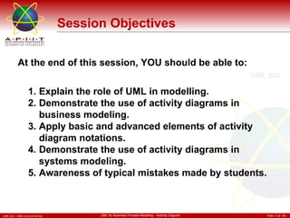
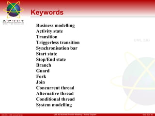

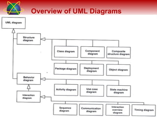


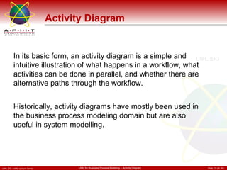
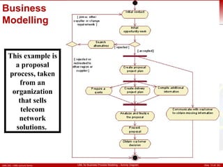
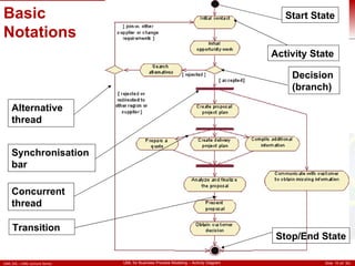
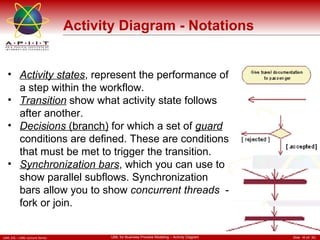
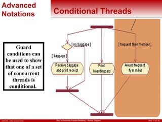
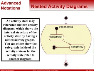
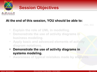
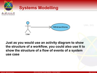
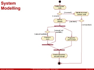
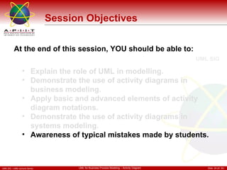
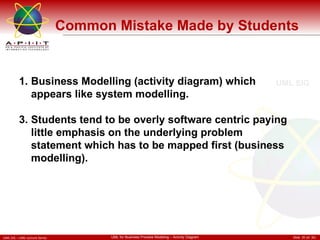

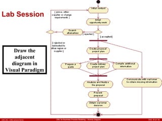

This document discusses using activity diagrams for business and systems modeling. It explains the basic and advanced elements of activity diagrams like activity states, transitions, decisions, synchronization bars, concurrent threads, alternative threads, conditional threads, nested activity diagrams and partitions. The objectives are to explain UML modeling, demonstrate activity diagram usage for business and systems modeling, apply activity diagram notations, and highlight common student mistakes.