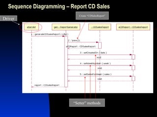
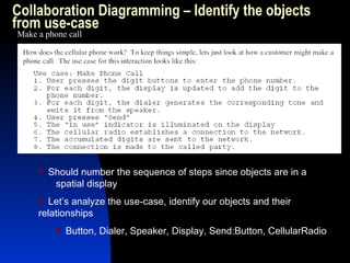
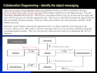
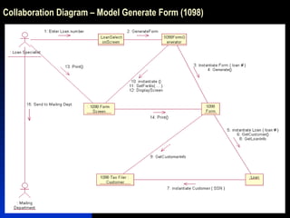
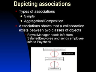
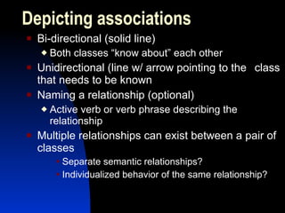
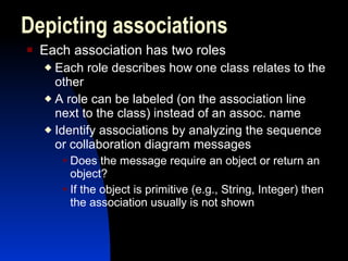
The document explains how to analyze systems using object interaction diagramming within the UML framework, focusing on relationships such as aggregation and composition. It details the construction of sequence and collaboration diagrams, emphasizing the importance of object messaging and multiplicity in modeling real-world scenarios. The presentation aims to enhance understanding of dynamic object behavior and improve the design process in software development.


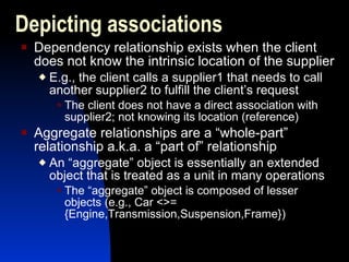
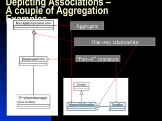
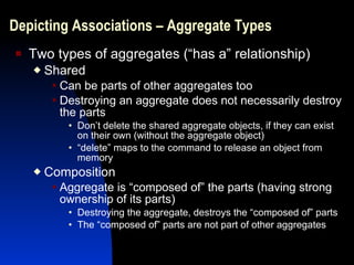
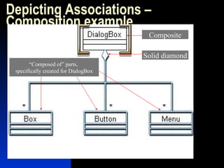
![Depicting Multiplicities in Associations – Example [0 to 1] InteractionUse to [many] Actions](https://image.slidesharecdn.com/ooadwithumlinteractiondiagramming-12756227623087-phpapp01/85/OOAD-with-UML-Interaction-Diagramming-32-320.jpg)


![Getting Started with Apache Spark: Big Data Made Simple [Free Meetup]](https://cdn.slidesharecdn.com/ss_thumbnails/apachesparkgettingstarted-260203175547-8361bcc3-thumbnail.jpg?width=640&height=640&fit=bounds)


