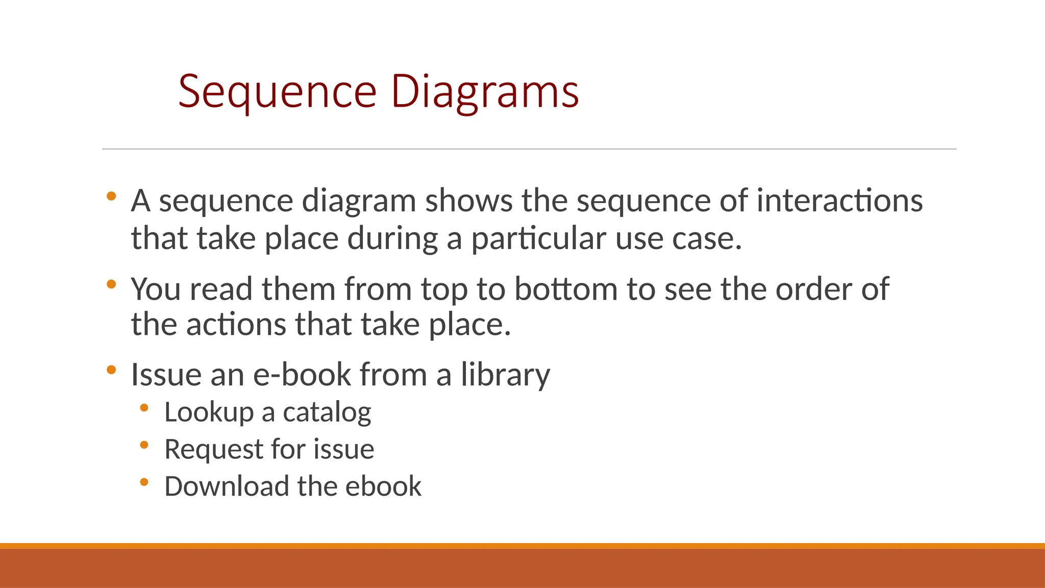
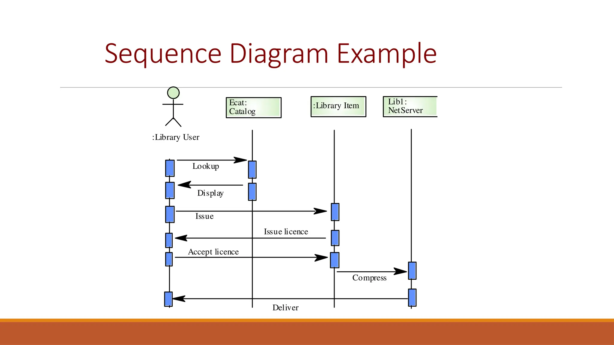
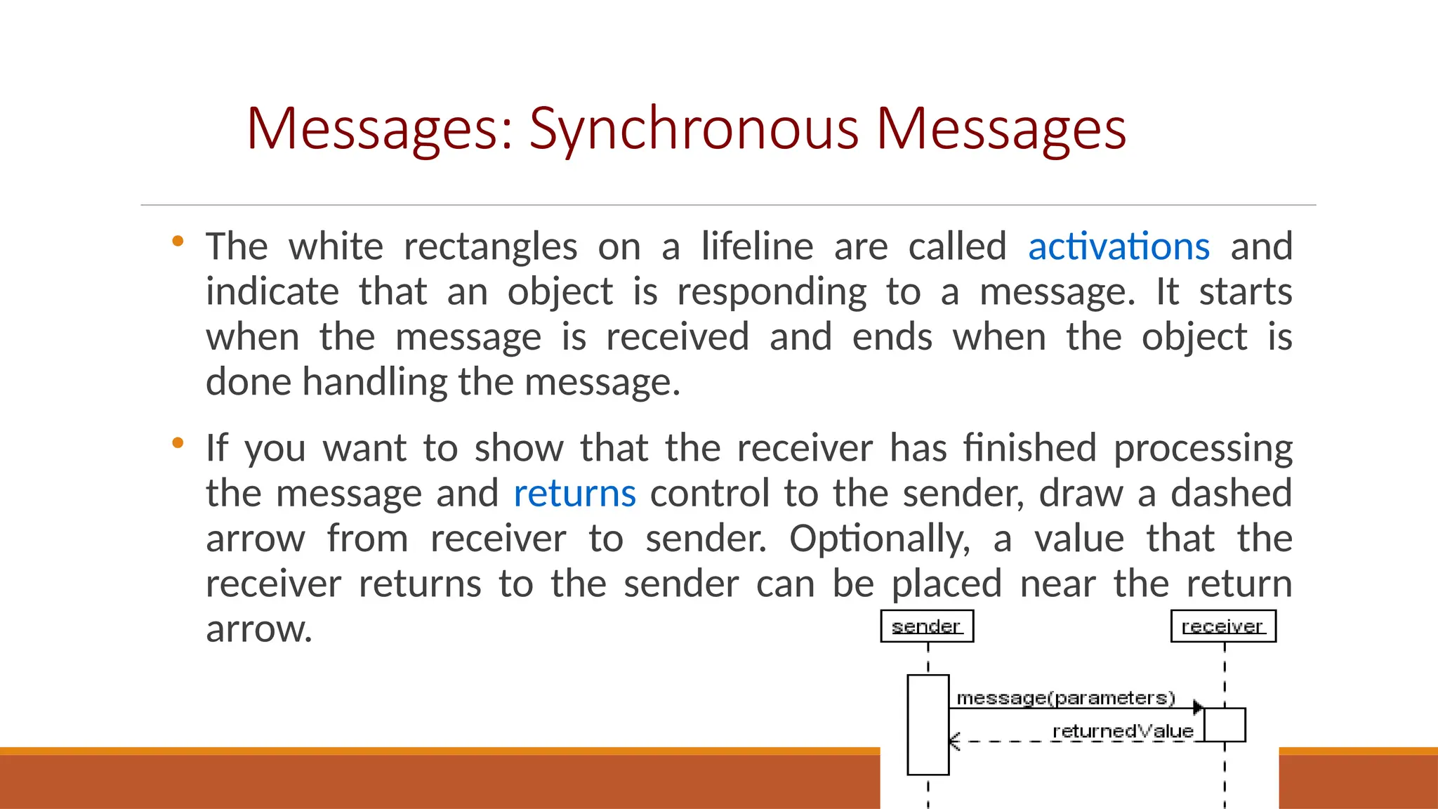
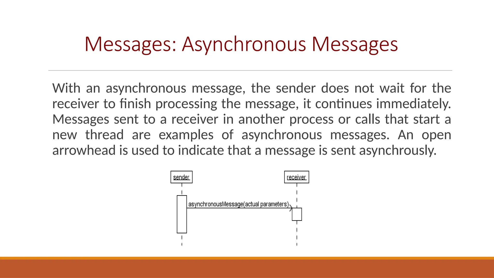
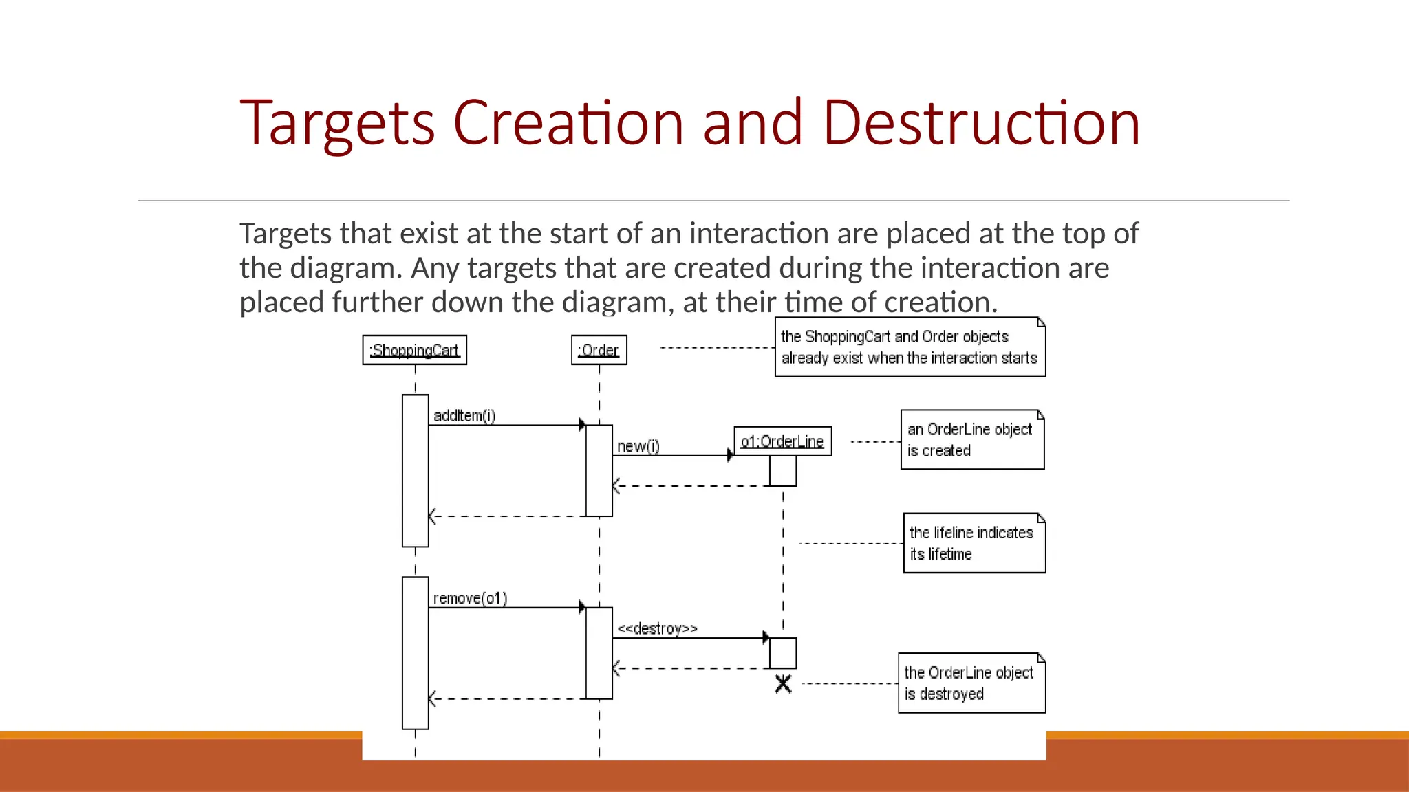
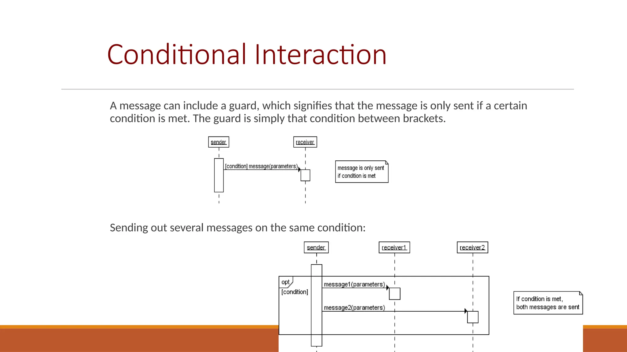
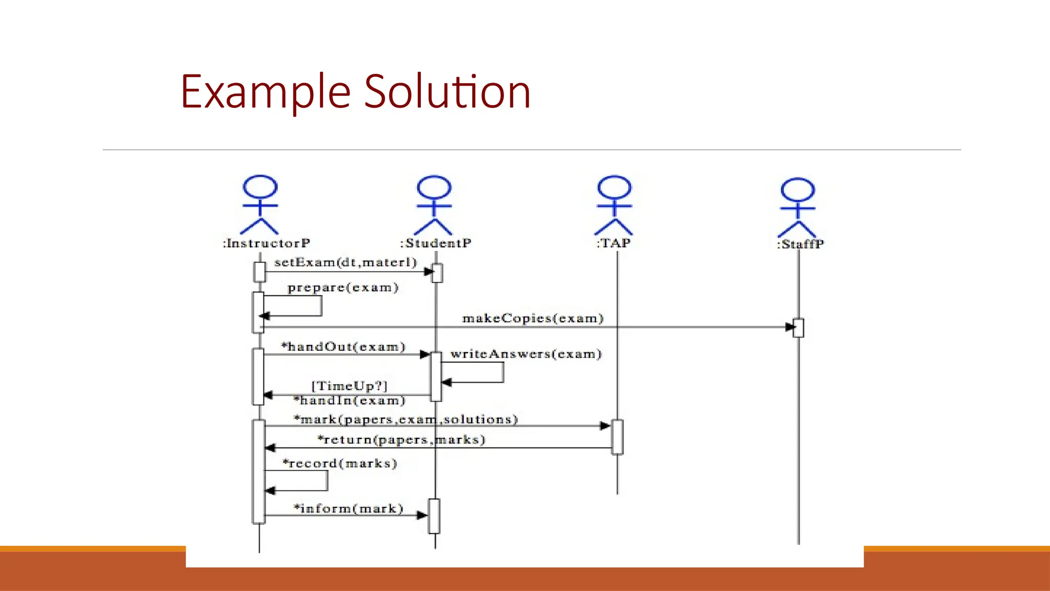
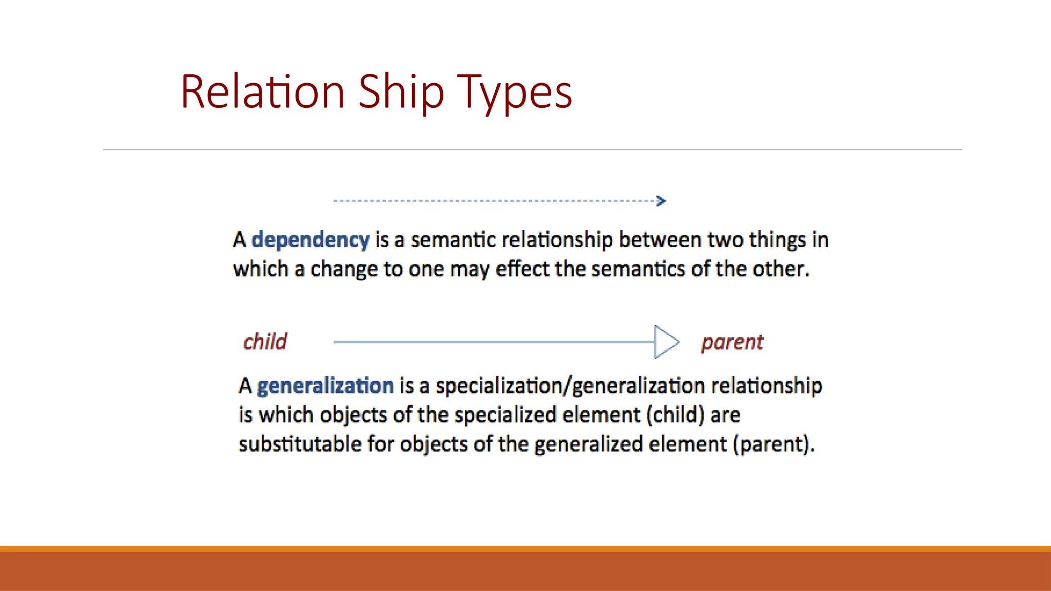
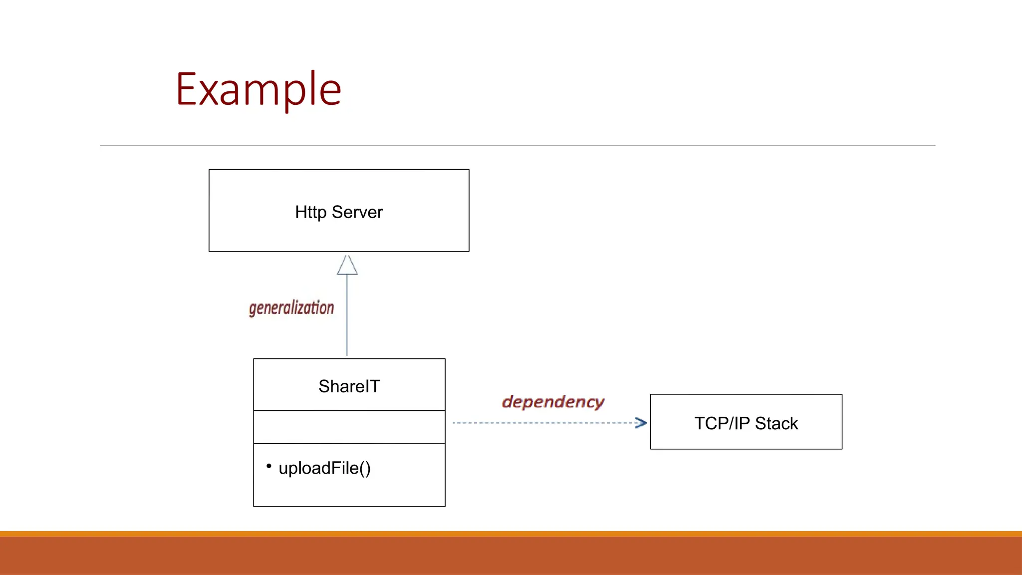
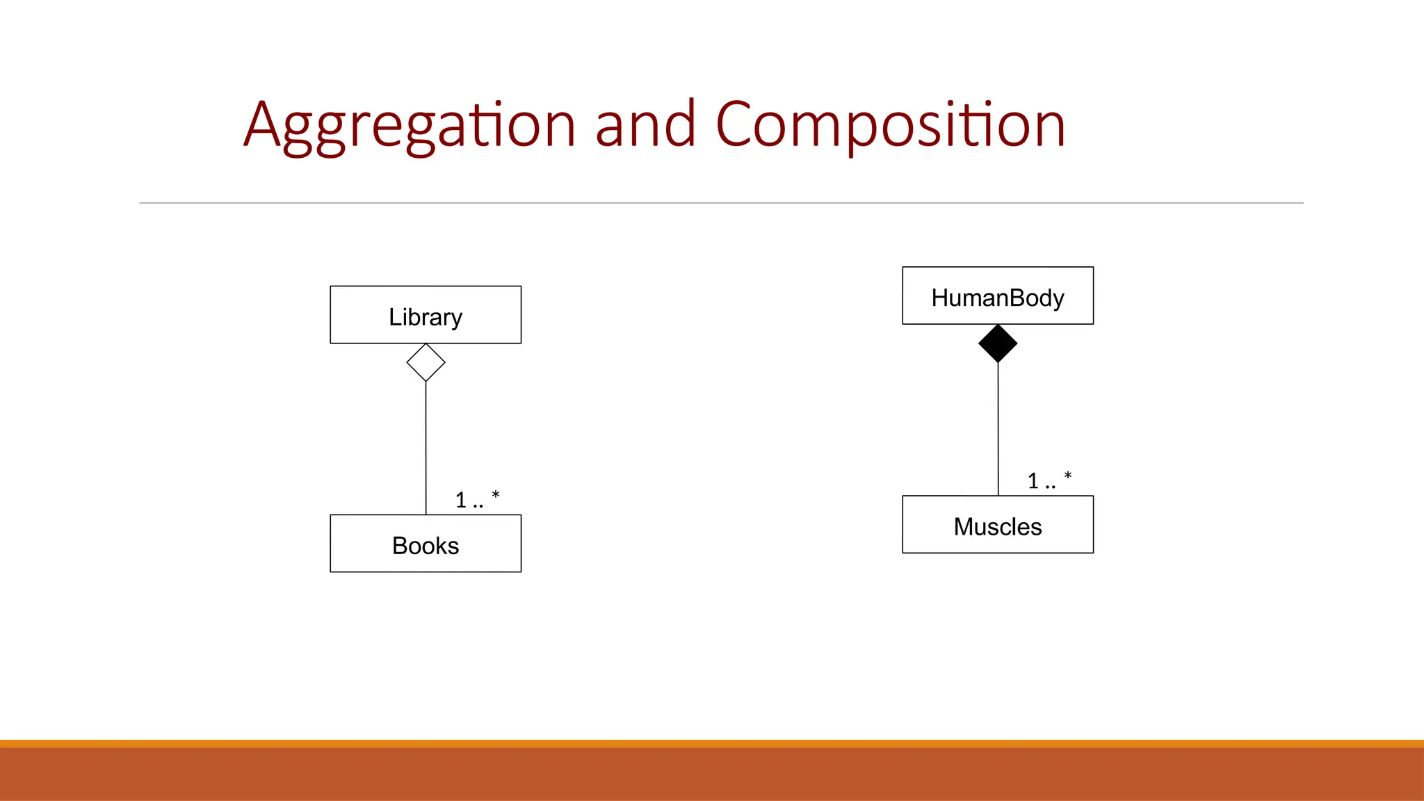
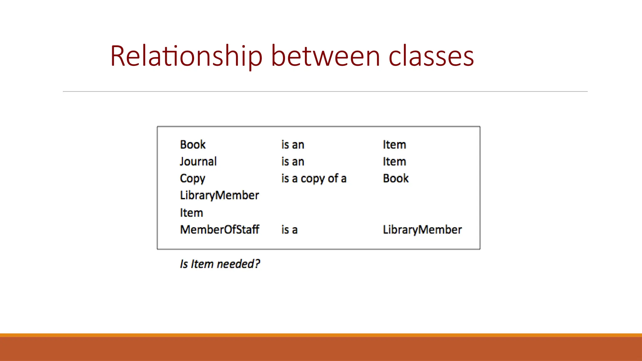
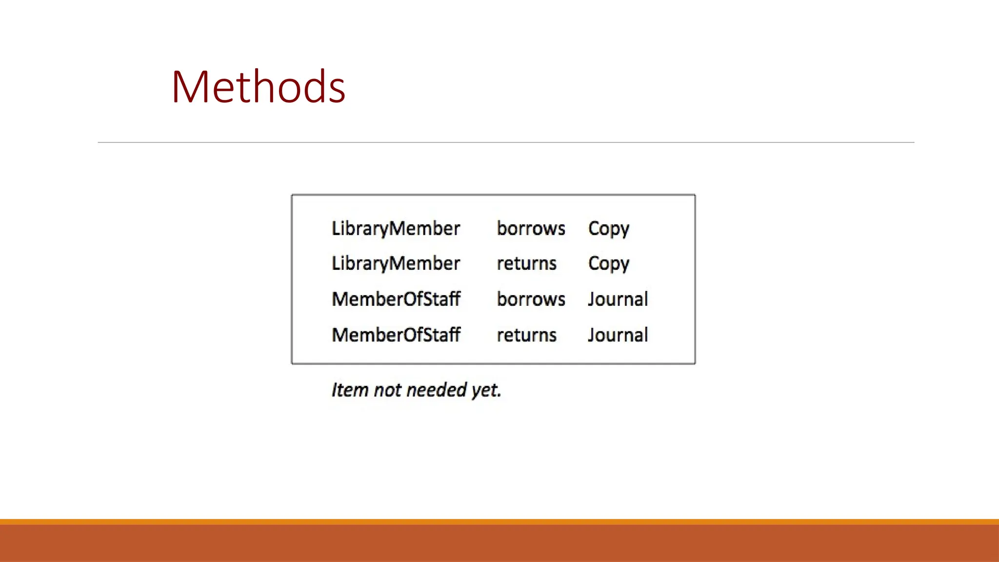
CHAPTER 5 SYSTEM MODELING
Software Engineering
LECTURE 17: SEQUENCE DIAGRAM AND CLASS DIAGRAM
1
Sequence Diagram
CHAPTER 5 SYSTEM MODELING 2
Sequence Diagrams

A sequence diagram shows the sequence of interactions
that take place during a particular use case.

You read them from top to bottom to see the order of
the actions that take place.

Issue an e-book from a library

Lookup a catalog

Request for issue

Download the ebook
Sequence Diagram Example
:Library User
Ecat:
Catalog
Lookup
Issue
Display
:Library Item Lib1:
NetServer
Issue licence
Accept licence
Compress
Deliver
Sequence Diagram Elements: Targets
Targets: Objects as well as classes can be
targets on a sequence diagram, which means
that messages can be sent to them. A target is
displayed as a rectangle with some text in it.
Below the target, its lifeline extends for as long
as the target exists. The lifeline is displayed as a
vertical dashed line.
Targets: Objects
Objects

Basic notation for an object is:

Both name and type are optional but atleast one should be present
Targets: Objects
As with any UML-element, you can add a stereotype to a target.
Targets: Objects
An object should be named only if at least one of the following
applies

You want to refer to it during the interaction as a message
parameter or return value

You don't mention its type

There are other anonymous objects of the same type and giving
them names is the only way to differentiate them
Targets: MultiObjects
When you want to show how a client interacts with the
elements of a collection, you can use a multiobject. Its
basic notation is
Again, a name and/or type can be specified. Note however
that the 'Type' part designates the type of the elements
and not the type of the collection itself.
Targets: Class

A basic notation for class is:

Only class messages (e.g. shared or static methods in
some programming languages) can be sent to a class.
Note that the text of a class is not underlined, which is
how you can distinguish it from an object.
Sequence Diagram Elements:
Messages

When a target sends a message to another target, it is
shown as an arrow between their lifelines. The arrow
originates at the sender and ends at the receiver. Near
the arrow, the name and parameters of the message are
shown.

Messages can be of two types

Synchronous Messages

Asynchronous Messages
Messages: Synchronous Messages

A synchronous message is used when the sender waits until the
receiver has finished processing the message, only then does the
caller continue (i.e. a blocking call). Most method calls in object-
oriented programming languages are synchronous. A closed and
filled arrowhead signifies that the message is sent
synchronously.
Messages: Synchronous Messages

The white rectangles on a lifeline are called activations and
indicate that an object is responding to a message. It starts
when the message is received and ends when the object is
done handling the message.

If you want to show that the receiver has finished processing
the message and returns control to the sender, draw a dashed
arrow from receiver to sender. Optionally, a value that the
receiver returns to the sender can be placed near the return
arrow.
Messages: Asynchronous Messages
With an asynchronous message, the sender does not wait for the
receiver to finish processing the message, it continues immediately.
Messages sent to a receiver in another process or calls that start a
new thread are examples of asynchronous messages. An open
arrowhead is used to indicate that a message is sent asynchrously.
Targets Creation and Destruction
Targets that exist at the start of an interaction are placed at the top of
the diagram. Any targets that are created during the interaction are
placed further down the diagram, at their time of creation.
Conditional Interaction
A message can include a guard, which signifies that the message is only sent if a certain
condition is met. The guard is simply that condition between brackets.
Sending out several messages on the same condition:
Alternative Interaction
If you want to show several alternative interactions, use an 'alt' combined fragment. The
combined fragment contains an operand for each alternative. Each alternative has a guard and
contains the interaction that occurs when the condition for that guard is met.
Repeated Interaction
When a message is prefixed with an asterisk (the '*'-symbol), it means that the message is sent
repeatedly. A guard indicates the condition that determines whether or not the message should
be sent (again). As long as the condition holds, the message is repeated.
Repeated Interaction
A more common use of repetition is sending the same message to
different elements in a collection. In such a scenario, the receiver of
the repeated message is a multiobject and the guard indicates the
condition that controls the repetition.
Example
To give an exam, an instructor first notifies the students of the exam date
and the material to be covered. She then prepares the exam paper (with
sample solutions), gets it copied to produce enough copies for the class,
and hands it out to students on the designated time and location. The
students write their answers to exam questions and hand in their papers to
the instructor. The instructor then gives the exam papers to the TAs, along
with sample solutions to each question, and gets them to mark it. She then
records all marks and returns the papers to the students.
Draw a sequence diagram that represents this process. Make sure to show
when is each actor participating in the process. Also, show the operation
that is carried out during each interaction, and what its arguments are
Example Solution
Structural models
CHAPTER 5 SYSTEM MODELING 22
30/10/2014
Structural Models

Structural models of software display the organization of a
system in terms of components that make up the system
and their relationship

Structural models may be

Static Models—structure of the system

Dynamic Models-- structure of the system when executing

Today's focus will be on class diagrams for modelling the
static structure of the program
Class Diagrams

Class diagrams are used when developing an object-oriented system model to
show the classes in a system and the associations between these classes.

An association is a link between classes that indicates that there is some
relationship between these classes.

When you are developing models during the early stages of the software
engineering process, objects represent something in the real world, such as a
patient, a prescription, doctor, etc.

A implementation is developed you usually need to define additional
implementation objects

Today we will focus on modeling real world objects as part of the requirement
or early stage software design.
UML Class Diagrams

Class diagrams in UML can be expressed at different level of
detail.

At the first stage of developing a model, look at the world and
identify the essential objects and represent them as class.

The simplest way is to write the name of the class in a box
Patient
UML Class Diagrams (cont)

You can also note the existence of an association by drawing a
line between the classes

You can annotate the relationship to show how many objects
are involved in the association
Patient PatientRecord
1 1
Class Associations

You can name the relationships and other multiplicities of
objects in any association are also possible as shown here:
Patient Doctor
* 1
ReferredBy
Patient
Medical
Condition
1..* 1..*
Diagnosed With
Adding Details to class diagrams

When showing the association between the classes it is convenient to
represent these classes in the simplest possible way.

To define them in more detail you add information about their attributes
and operations
Patient

Name

Registration Number

Blood Group

medicines

getPatientName()

addMedicine()

RemoveMedicine()

...
Relation Ship Types
Example
Http Server
ShareIT

uploadFile()
TCP/IP Stack
Aggregation and Composition
Library
Books
1 .. *
HumanBody
Muscles
1 .. *
Deciding Which Classes To Use
Noun Identification: A library System
Candidate Classes
Relationship between classes
Methods
A Possible Class Diagram
Key points
A model is an abstract view of a system that ignores system details. Complementary system
models can be developed to show the system’s context, interactions, structure and behavior.
Context models show how a system that is being modeled is positioned in an environment with
other systems and processes.
Use case diagrams and sequence diagrams are used to describe the interactions between users
and systems in the system being designed. Use cases describe interactions between a system
and external actors; sequence diagrams add more information to these by showing interactions
between system objects.
Structural models show the organization and architecture of a system. Class diagrams are used
to define the static structure of classes in a system and their associations.
CHAPTER 5 SYSTEM MODELING 40
Key points
Behavioral models are used to describe the dynamic behavior of an executing system.
This behavior can be modeled from the perspective of the data processed by the
system, or by the events that stimulate responses from a system.
Activity diagrams may be used to model the processing of data, where each activity
represents one process step.
CHAPTER 5 SYSTEM MODELING 41

Lecture 17 -18 - Sequence Diagram - Class Diagram.pptx

  • 1.
    CHAPTER 5 SYSTEMMODELING Software Engineering LECTURE 17: SEQUENCE DIAGRAM AND CLASS DIAGRAM 1
  • 2.
    Sequence Diagram CHAPTER 5SYSTEM MODELING 2
  • 3.
    Sequence Diagrams  A sequencediagram shows the sequence of interactions that take place during a particular use case.  You read them from top to bottom to see the order of the actions that take place.  Issue an e-book from a library  Lookup a catalog  Request for issue  Download the ebook
  • 4.
    Sequence Diagram Example :LibraryUser Ecat: Catalog Lookup Issue Display :Library Item Lib1: NetServer Issue licence Accept licence Compress Deliver
  • 5.
    Sequence Diagram Elements:Targets Targets: Objects as well as classes can be targets on a sequence diagram, which means that messages can be sent to them. A target is displayed as a rectangle with some text in it. Below the target, its lifeline extends for as long as the target exists. The lifeline is displayed as a vertical dashed line.
  • 6.
    Targets: Objects Objects  Basic notationfor an object is:  Both name and type are optional but atleast one should be present
  • 7.
    Targets: Objects As withany UML-element, you can add a stereotype to a target.
  • 8.
    Targets: Objects An objectshould be named only if at least one of the following applies  You want to refer to it during the interaction as a message parameter or return value  You don't mention its type  There are other anonymous objects of the same type and giving them names is the only way to differentiate them
  • 9.
    Targets: MultiObjects When youwant to show how a client interacts with the elements of a collection, you can use a multiobject. Its basic notation is Again, a name and/or type can be specified. Note however that the 'Type' part designates the type of the elements and not the type of the collection itself.
  • 10.
    Targets: Class  A basicnotation for class is:  Only class messages (e.g. shared or static methods in some programming languages) can be sent to a class. Note that the text of a class is not underlined, which is how you can distinguish it from an object.
  • 11.
    Sequence Diagram Elements: Messages  Whena target sends a message to another target, it is shown as an arrow between their lifelines. The arrow originates at the sender and ends at the receiver. Near the arrow, the name and parameters of the message are shown.  Messages can be of two types  Synchronous Messages  Asynchronous Messages
  • 12.
    Messages: Synchronous Messages  Asynchronous message is used when the sender waits until the receiver has finished processing the message, only then does the caller continue (i.e. a blocking call). Most method calls in object- oriented programming languages are synchronous. A closed and filled arrowhead signifies that the message is sent synchronously.
  • 13.
    Messages: Synchronous Messages  Thewhite rectangles on a lifeline are called activations and indicate that an object is responding to a message. It starts when the message is received and ends when the object is done handling the message.  If you want to show that the receiver has finished processing the message and returns control to the sender, draw a dashed arrow from receiver to sender. Optionally, a value that the receiver returns to the sender can be placed near the return arrow.
  • 14.
    Messages: Asynchronous Messages Withan asynchronous message, the sender does not wait for the receiver to finish processing the message, it continues immediately. Messages sent to a receiver in another process or calls that start a new thread are examples of asynchronous messages. An open arrowhead is used to indicate that a message is sent asynchrously.
  • 15.
    Targets Creation andDestruction Targets that exist at the start of an interaction are placed at the top of the diagram. Any targets that are created during the interaction are placed further down the diagram, at their time of creation.
  • 16.
    Conditional Interaction A messagecan include a guard, which signifies that the message is only sent if a certain condition is met. The guard is simply that condition between brackets. Sending out several messages on the same condition:
  • 17.
    Alternative Interaction If youwant to show several alternative interactions, use an 'alt' combined fragment. The combined fragment contains an operand for each alternative. Each alternative has a guard and contains the interaction that occurs when the condition for that guard is met.
  • 18.
    Repeated Interaction When amessage is prefixed with an asterisk (the '*'-symbol), it means that the message is sent repeatedly. A guard indicates the condition that determines whether or not the message should be sent (again). As long as the condition holds, the message is repeated.
  • 19.
    Repeated Interaction A morecommon use of repetition is sending the same message to different elements in a collection. In such a scenario, the receiver of the repeated message is a multiobject and the guard indicates the condition that controls the repetition.
  • 20.
    Example To give anexam, an instructor first notifies the students of the exam date and the material to be covered. She then prepares the exam paper (with sample solutions), gets it copied to produce enough copies for the class, and hands it out to students on the designated time and location. The students write their answers to exam questions and hand in their papers to the instructor. The instructor then gives the exam papers to the TAs, along with sample solutions to each question, and gets them to mark it. She then records all marks and returns the papers to the students. Draw a sequence diagram that represents this process. Make sure to show when is each actor participating in the process. Also, show the operation that is carried out during each interaction, and what its arguments are
  • 21.
  • 22.
    Structural models CHAPTER 5SYSTEM MODELING 22 30/10/2014
  • 23.
    Structural Models  Structural modelsof software display the organization of a system in terms of components that make up the system and their relationship  Structural models may be  Static Models—structure of the system  Dynamic Models-- structure of the system when executing  Today's focus will be on class diagrams for modelling the static structure of the program
  • 24.
    Class Diagrams  Class diagramsare used when developing an object-oriented system model to show the classes in a system and the associations between these classes.  An association is a link between classes that indicates that there is some relationship between these classes.  When you are developing models during the early stages of the software engineering process, objects represent something in the real world, such as a patient, a prescription, doctor, etc.  A implementation is developed you usually need to define additional implementation objects  Today we will focus on modeling real world objects as part of the requirement or early stage software design.
  • 25.
    UML Class Diagrams  Classdiagrams in UML can be expressed at different level of detail.  At the first stage of developing a model, look at the world and identify the essential objects and represent them as class.  The simplest way is to write the name of the class in a box Patient
  • 26.
    UML Class Diagrams(cont)  You can also note the existence of an association by drawing a line between the classes  You can annotate the relationship to show how many objects are involved in the association Patient PatientRecord Patient PatientRecord 1 1
  • 27.
    Class Associations  You canname the relationships and other multiplicities of objects in any association are also possible as shown here: Patient Doctor * 1 ReferredBy Patient Medical Condition 1..* 1..* Diagnosed With
  • 28.
    Adding Details toclass diagrams  When showing the association between the classes it is convenient to represent these classes in the simplest possible way.  To define them in more detail you add information about their attributes and operations Patient  Name  Registration Number  Blood Group  medicines  getPatientName()  addMedicine()  RemoveMedicine()  ...
  • 29.
  • 30.
  • 31.
    Aggregation and Composition Library Books 1.. * HumanBody Muscles 1 .. *
  • 32.
  • 33.
  • 34.
    Noun Identification: Alibrary System
  • 35.
    Noun Identification: Alibrary System
  • 36.
  • 37.
  • 38.
  • 39.
  • 40.
    Key points A modelis an abstract view of a system that ignores system details. Complementary system models can be developed to show the system’s context, interactions, structure and behavior. Context models show how a system that is being modeled is positioned in an environment with other systems and processes. Use case diagrams and sequence diagrams are used to describe the interactions between users and systems in the system being designed. Use cases describe interactions between a system and external actors; sequence diagrams add more information to these by showing interactions between system objects. Structural models show the organization and architecture of a system. Class diagrams are used to define the static structure of classes in a system and their associations. CHAPTER 5 SYSTEM MODELING 40
  • 41.
    Key points Behavioral modelsare used to describe the dynamic behavior of an executing system. This behavior can be modeled from the perspective of the data processed by the system, or by the events that stimulate responses from a system. Activity diagrams may be used to model the processing of data, where each activity represents one process step. CHAPTER 5 SYSTEM MODELING 41