Downloaded 44 times

![Introduction
Solution
• Kotb and Katayama [1] proposed a novel XML
semantics approach for checking the semantic
consistency of XML document using attribute
grammar techniques.
• Shen et al. [2] implemented a toolset which could
examine both static and dynamic aspects of a model.
The toolset was based on the semantic model using
Abstract State Machines presented in [3].
[1] Y. Kotb and T. Katayama, “Consistency Checking of UML Model Diagrams Using the XML Semantics Approach”. th international conference on World Wide Web,
(2005), May 10-14; Chiba, Japan.
[2] W. Shen, K. Compton, and J. Huggins, “A Toolset for Supporting UML Static and Dynamic Model Checking”. 26th International Computer Software and Applications
Conference on Prolonging Software Life: Development and Redevelopment, IEEE Computer Society, (2002), August 26-29; Oxford, English.
[3] Y. Gurevich, “Sequential Abstract State Machines Capture Sequential Algorithms”. ACM Transactions on Computational Logic, vol. 1, no.1, (2000), pp.77-111.](https://image.slidesharecdn.com/extendadlpresentationenv-130710015318-phpapp01/75/Enhancement-of-Action-Description-Language-for-UML-Activity-Diagram-Review-7-2048.jpg)
![Introduction
Solution
• Flater et al. [4] proposed human-readable Activity
Diagram Linear Form (ADLF) for describing activity
diagrams in text format.
• Narkngam and Limpiyakorn [5], [6], [7] introduced a
preventive approach to rendering valid activity
diagrams with a domain specific language called
Action Description Language (ADL).
[4] D. Flater, P.A. Martin, and M.L. Crane, “Rendering UML Activity Diagrams as Human-Readable Text”. Proceedings of the 2009 International Conference on Information and Knowledge Engineering, (2009),
July 13-16; Las Vegas, United States.
[5] C. Narkngam, Y. Limpiyakorn, “Rendering UML Activity Diagrams as a Domain Specific Language - ADL”. th International Conference on Software Engineering and Knowledge Engineering, (2012),
July 1-3; San Francisco, USA.
[6] C. Narkngam, Y. Limpiyakorn, “Designing a Domain Specific Language for UML Activity Diagram”. 4th International Conference on Computer Engineering and Technology, (2012), May 12-13; Bangkok, Thailand.
[7] C. Narkngam and Y. Limpiyakorn, “Domain Specific Language for Activity Diagram”, Ramkhamhaeng Journal of Engineering, vol. 1, (2012).](https://image.slidesharecdn.com/extendadlpresentationenv-130710015318-phpapp01/75/Enhancement-of-Action-Description-Language-for-UML-Activity-Diagram-Review-8-2048.jpg)
![Introduction
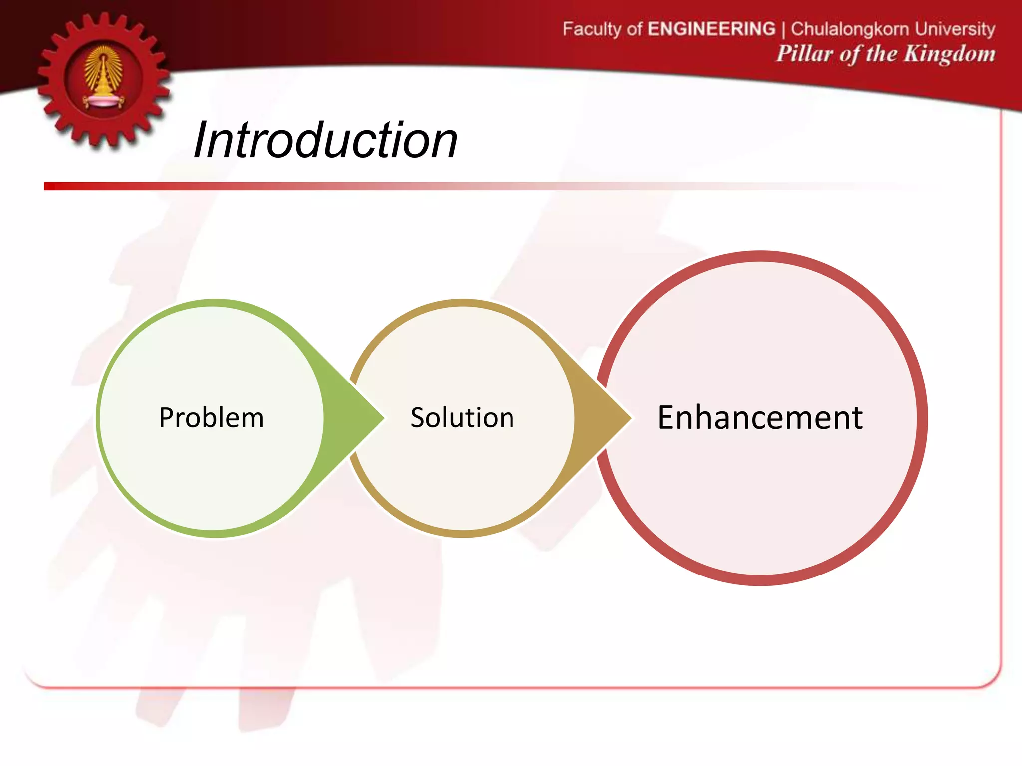
Enhancement
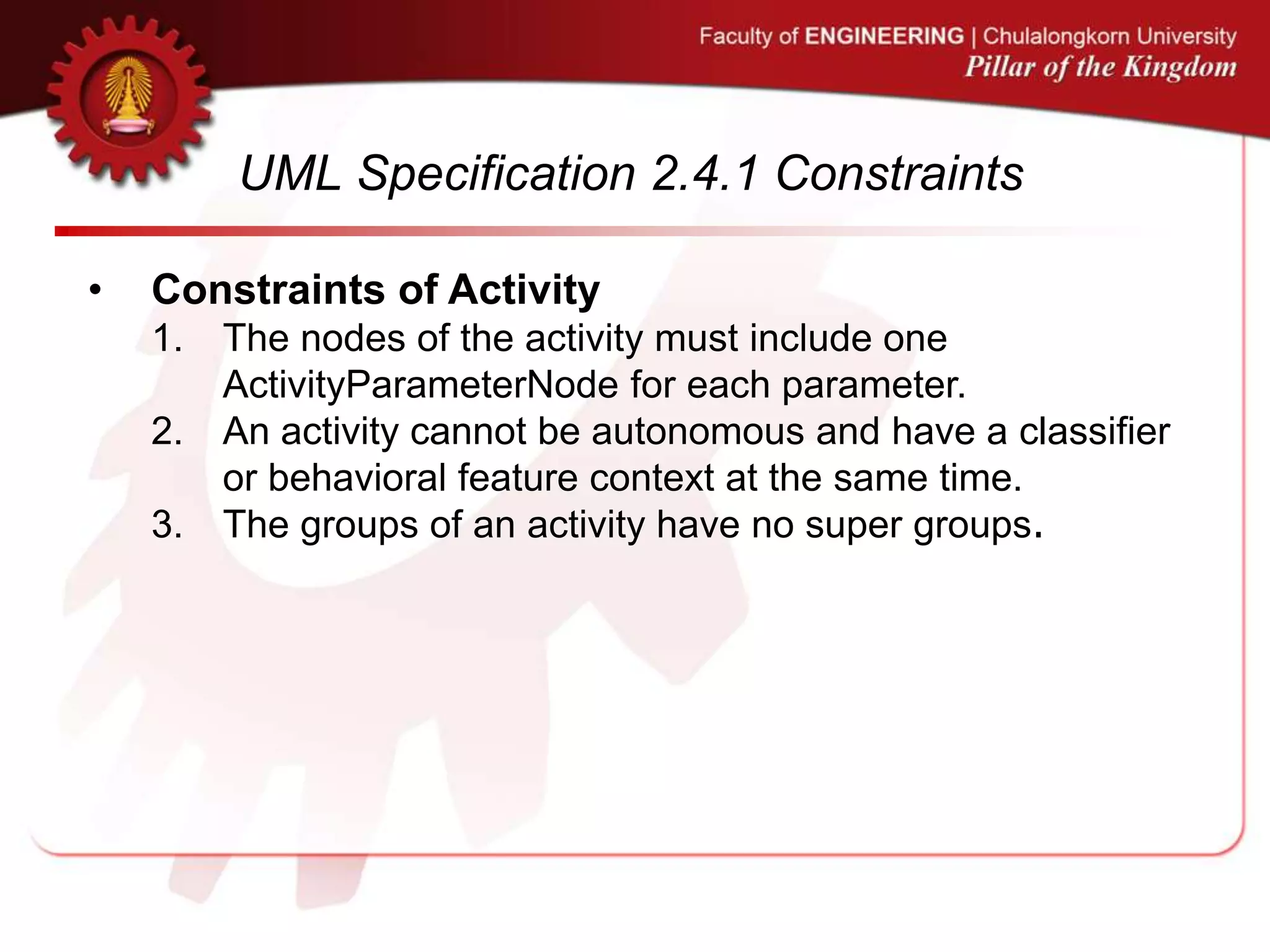
• In this research, the enhancement of the Action
Description Language invented in [5], [6], [7] is carried
out to verify existing activity diagrams whether they
conform to the UML specification version 2.4.1.
• Currently, the prototype developed in this work can
merely inspect the activity diagrams created by
ArgoUML and Modelio due to the restriction caused by
the variations of the XMI format generated by different
UML tools.
[5] C. Narkngam, Y. Limpiyakorn, “Rendering UML Activity Diagrams as a Domain Specific Language - ADL”. th International Conference on Software Engineering and Knowledge Engineering, (2012),
July 1-3; San Francisco, USA.
[6] C. Narkngam, Y. Limpiyakorn, “Designing a Domain Specific Language for UML Activity Diagram”. 4th International Conference on Computer Engineering and Technology, (2012), May 12-13; Bangkok, Thailand.
[7] C. Narkngam and Y. Limpiyakorn, “Domain Specific Language for Activity Diagram”, Ramkhamhaeng Journal of Engineering, vol. 1, (2012).](https://image.slidesharecdn.com/extendadlpresentationenv-130710015318-phpapp01/75/Enhancement-of-Action-Description-Language-for-UML-Activity-Diagram-Review-9-2048.jpg)
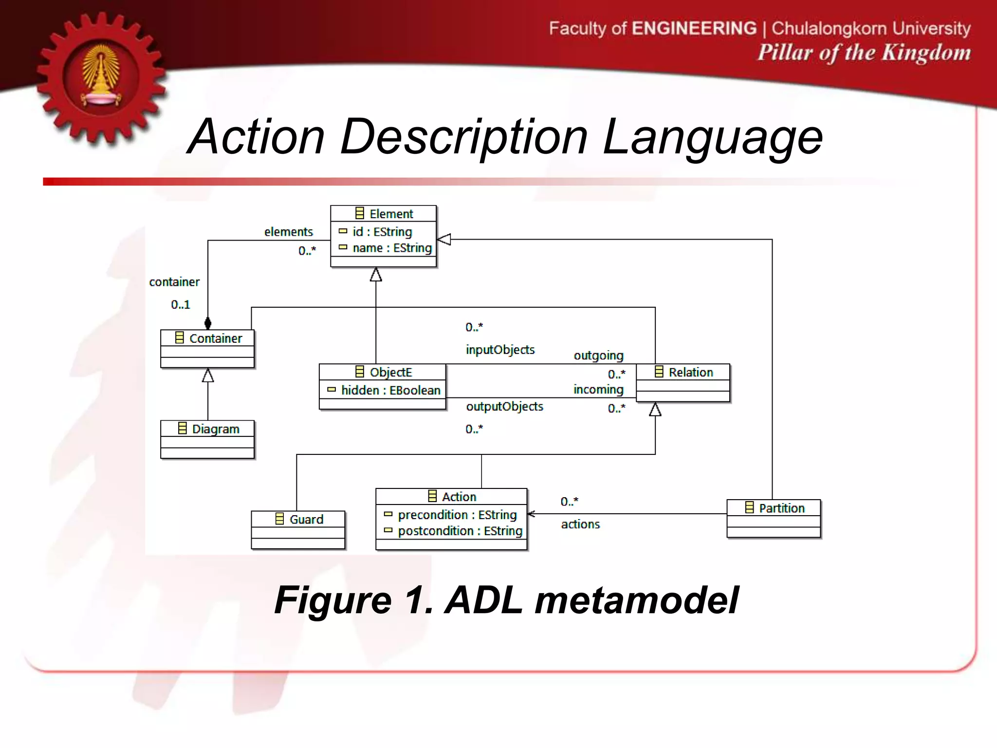
![Action Description Language
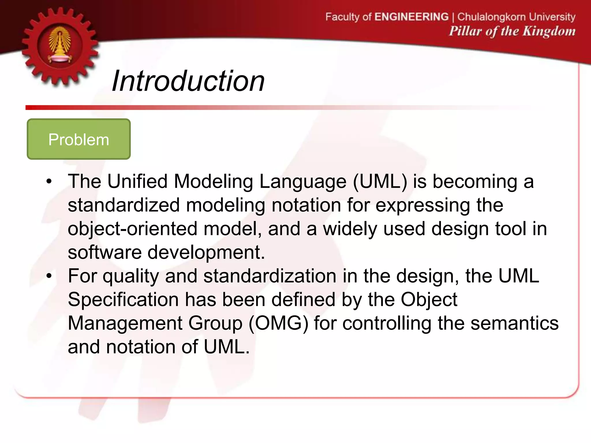
• Constraints can be defined as validation and verification
rules described in [7], serving the purposes of preventing
data inconsistency, and fortifying conformance to UML
specification, respectively.
• Representation can be visualized with a digraph using
Graphviz as used in the research or any other graph
visualization software.
[7] C. Narkngam and Y. Limpiyakorn, “Domain Specific Language for Activity Diagram”, Ramkhamhaeng Journal of Engineering, vol. 1, (2012).](https://image.slidesharecdn.com/extendadlpresentationenv-130710015318-phpapp01/75/Enhancement-of-Action-Description-Language-for-UML-Activity-Diagram-Review-14-2048.jpg)
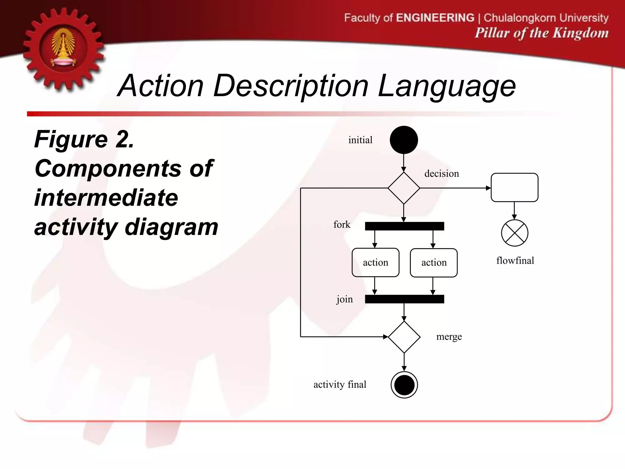
![Action Description Language
• The current ADL covers the generation of intermediate
activity diagrams as shown in Figure 2.
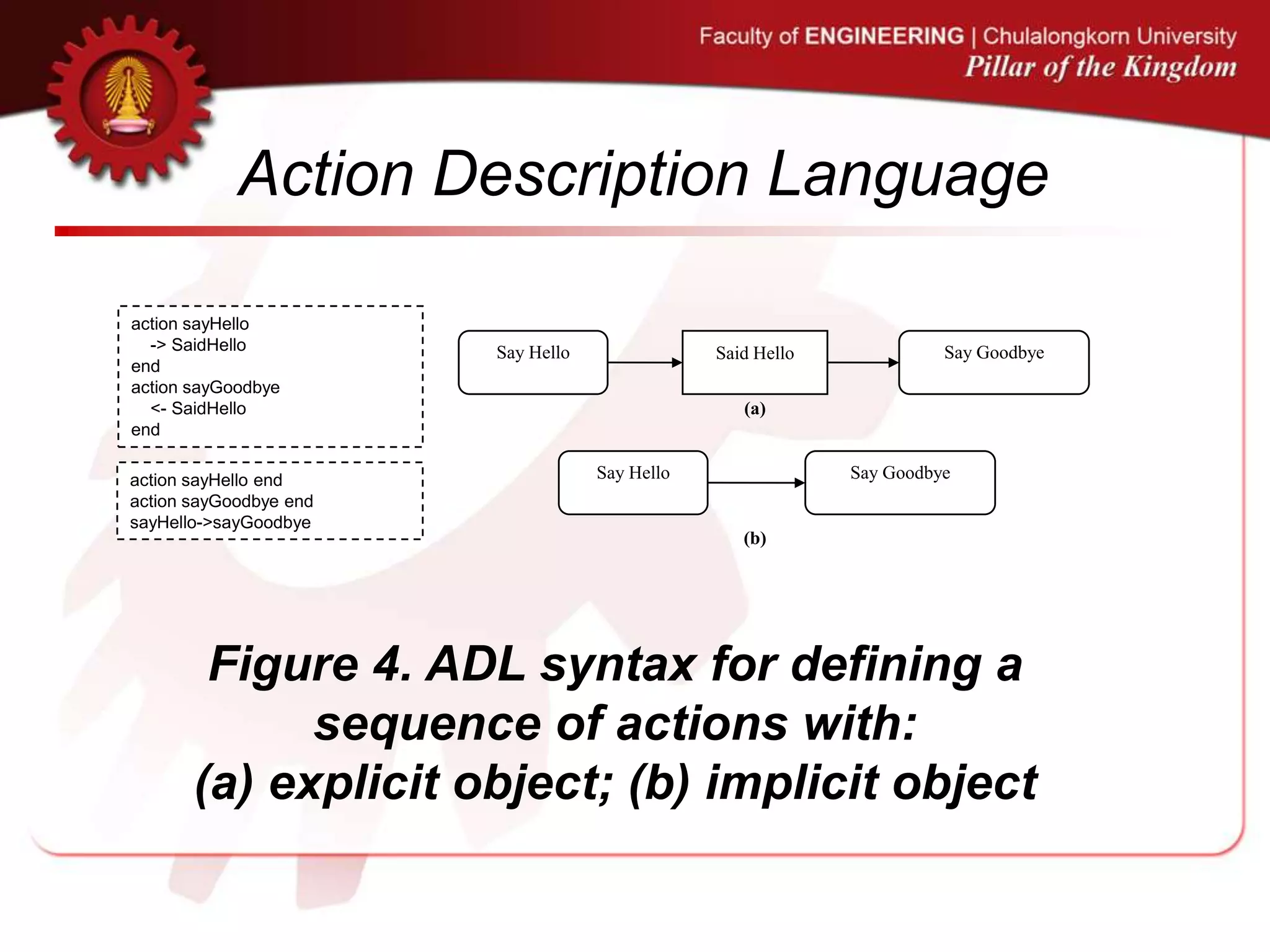
• The research work [5] has defined the syntax of ADL for
an action, a sequence of actions, and a decision, as
illustrated in Figure 3, Figure 4, and Figure 5,
respectively.
[5] C. Narkngam, Y. Limpiyakorn, “Rendering UML Activity Diagrams as a Domain Specific Language - ADL”. th International Conference on Software Engineering and Knowledge Engineering, (2012),
July 1-3; San Francisco, USA.](https://image.slidesharecdn.com/extendadlpresentationenv-130710015318-phpapp01/75/Enhancement-of-Action-Description-Language-for-UML-Activity-Diagram-Review-15-2048.jpg)
![Action Description Language
action id [[isLocallyReentrant=[true|false]]]
[name 'string']
[<- OID1[,OID2...[,OIDN]]] –-input objects
[-> OID3[,OID4...[,OIDN]]] –-output objects
[precondition 'string']
[postcondition 'string']
end
Figure 3. ADL syntax for defining an action](https://image.slidesharecdn.com/extendadlpresentationenv-130710015318-phpapp01/75/Enhancement-of-Action-Description-Language-for-UML-Activity-Diagram-Review-17-2048.jpg)
![Action Description Language
decision ['input']
if 'condition1' then id1
if 'condition2' then id2
...
end
Figure 5. ADL syntax for defining a decision](https://image.slidesharecdn.com/extendadlpresentationenv-130710015318-phpapp01/75/Enhancement-of-Action-Description-Language-for-UML-Activity-Diagram-Review-19-2048.jpg)
![Automation of Activity Diagram Review
• This paper presents the corrective approach to
reviewing the existing UML activity diagrams.
• The review process of UML activity diagrams
consists of four main steps.
• Figure 6 illustrates the research method how
we adapt ADL for verifying the conformance to
UML specification of existing activity diagrams.
[5] C. Narkngam, Y. Limpiyakorn, “Rendering UML Activity Diagrams as a Domain Specific Language - ADL”. th International Conference on Software Engineering and Knowledge Engineering, (2012),
July 1-3; San Francisco, USA.
[6] C. Narkngam, Y. Limpiyakorn, “Designing a Domain Specific Language for UML Activity Diagram”. 4th International Conference on Computer Engineering and Technology, (2012), May 12-13; Bangkok, Thailand.
[7] C. Narkngam and Y. Limpiyakorn, “Domain Specific Language for Activity Diagram”, Ramkhamhaeng Journal of Engineering, vol. 1, (2012).](https://image.slidesharecdn.com/extendadlpresentationenv-130710015318-phpapp01/75/Enhancement-of-Action-Description-Language-for-UML-Activity-Diagram-Review-21-2048.jpg)
![Figure 6. Review
process of UML
activity diagram
1 Standardize
XMI file of activity
diagram with mapping
rules
Activity diagram in
XMI format
Standardized XMI-
formatted activity
diagram
2. Generate
ADL script
ADL script
3.Verify &
Generate
inspection report
Intermediate activity
diagram metamodel
Java ANTLR grammar
Inspection result
UML 2.4.1 constraints
ADL semantic model
4. Parse ADL
script
[conform with UML]
[not conform with UML]
Valid ADL script
ADL metamodel
ADL ANTLR
grammar](https://image.slidesharecdn.com/extendadlpresentationenv-130710015318-phpapp01/75/Enhancement-of-Action-Description-Language-for-UML-Activity-Diagram-Review-22-2048.jpg)
![1. Standardize
XMI file of
activity diagram
with mapping
rules
1 Standardize
XMI file of activity
diagram with mapping
rules
Activity diagram in
XMI format
Standardized XMI-
formatted activity
diagram
2. Generate
ADL script
ADL script
3.Verify &
Generate
inspection report
Intermediate activity
diagram metamodel
Java ANTLR grammar
Inspection result
UML 2.4.1 constraints
ADL semantic model
4. Parse ADL
script
[conform with UML]
[not conform with UML]
Valid ADL script
ADL metamodel
ADL ANTLR
grammar](https://image.slidesharecdn.com/extendadlpresentationenv-130710015318-phpapp01/75/Enhancement-of-Action-Description-Language-for-UML-Activity-Diagram-Review-23-2048.jpg)
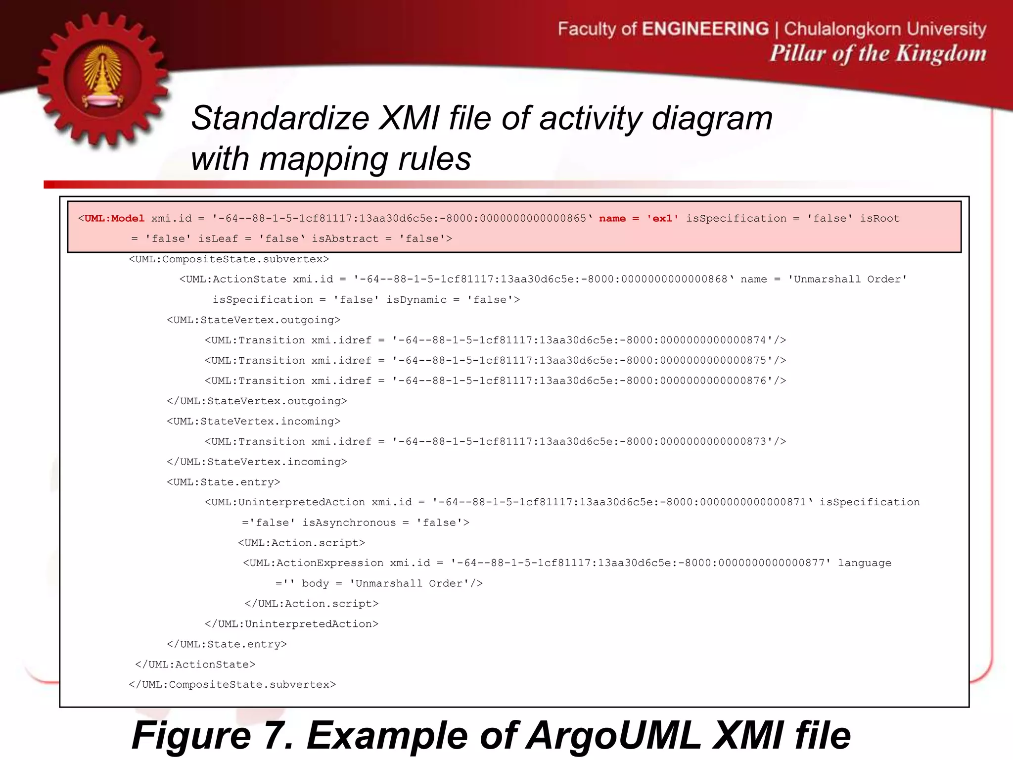
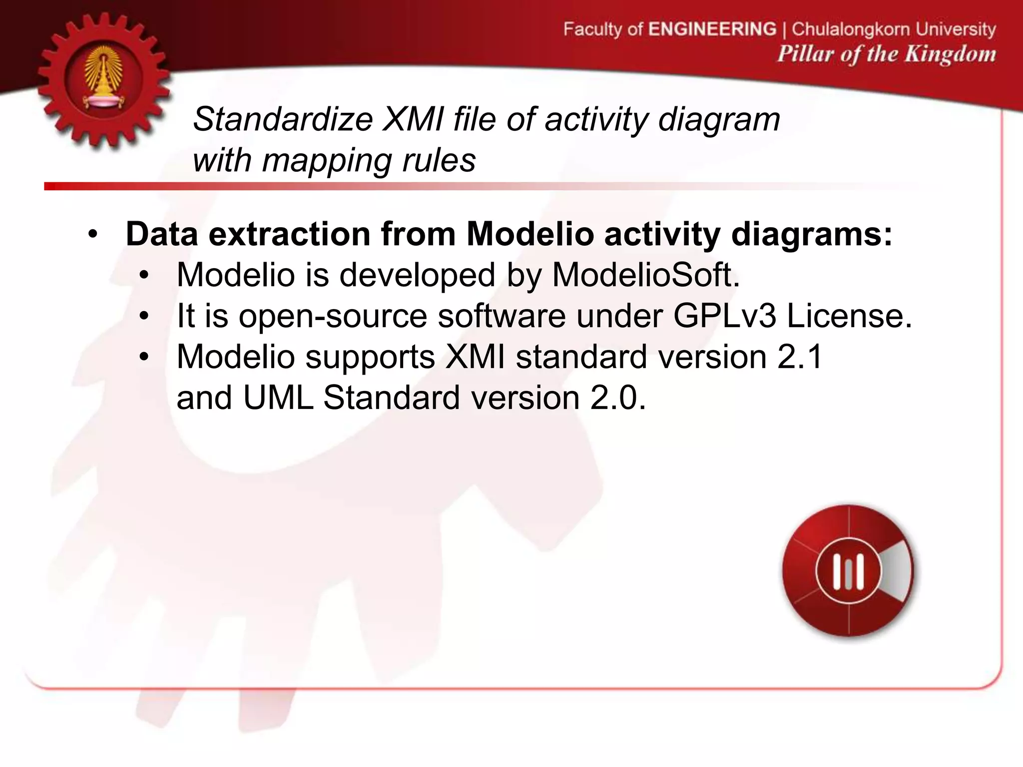
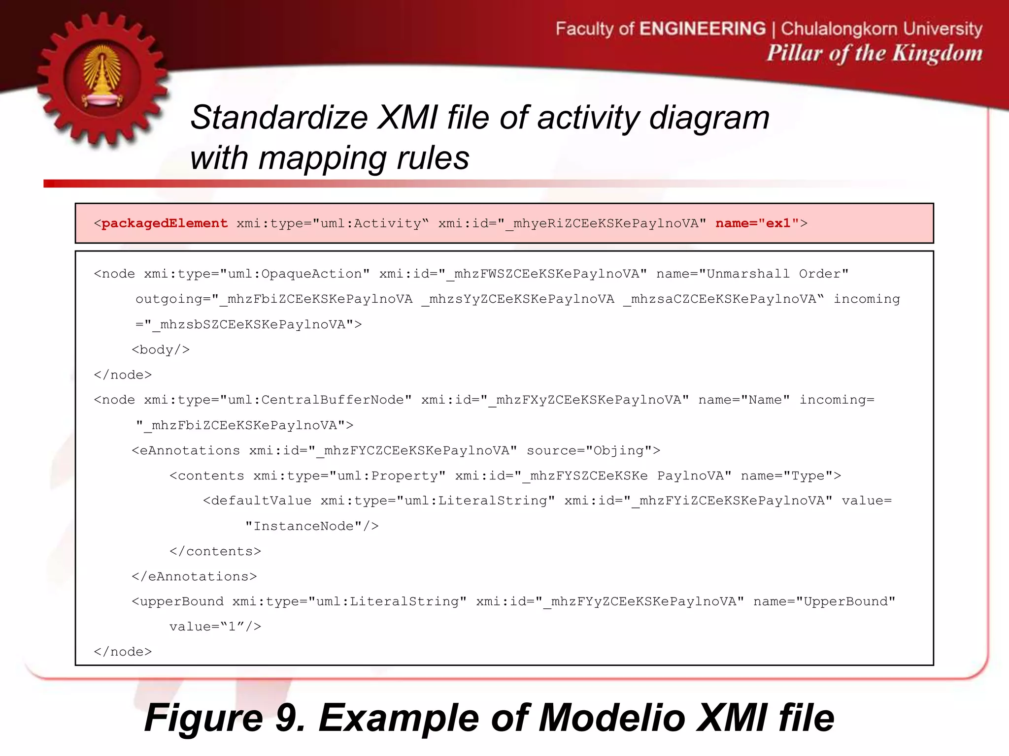
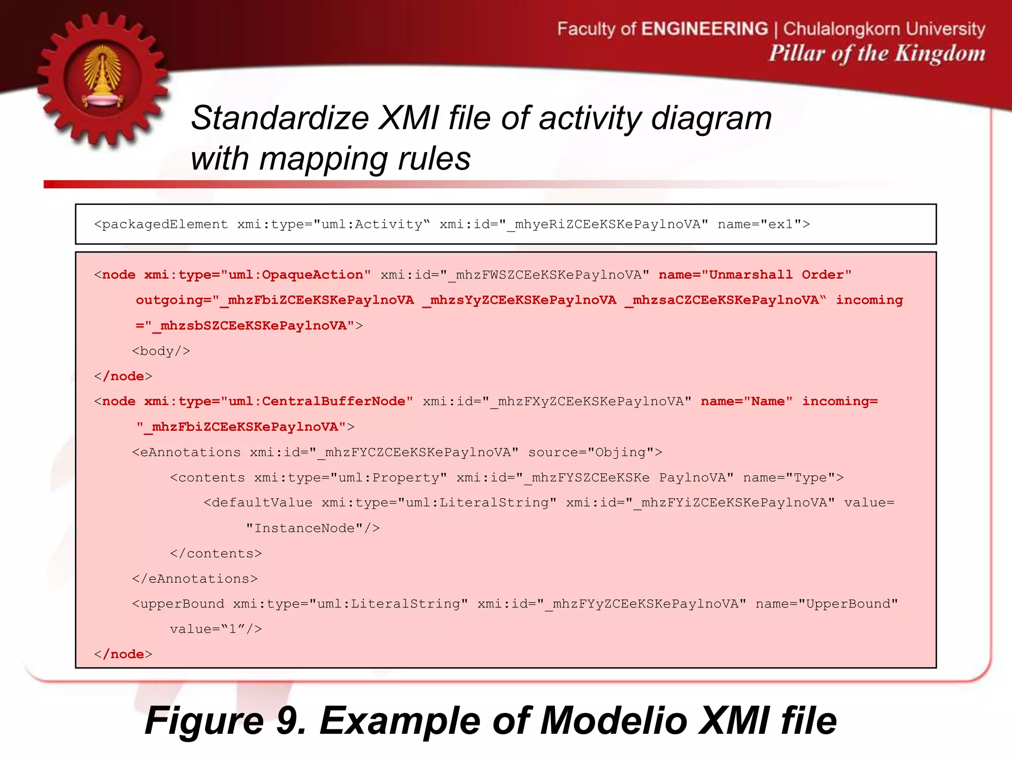
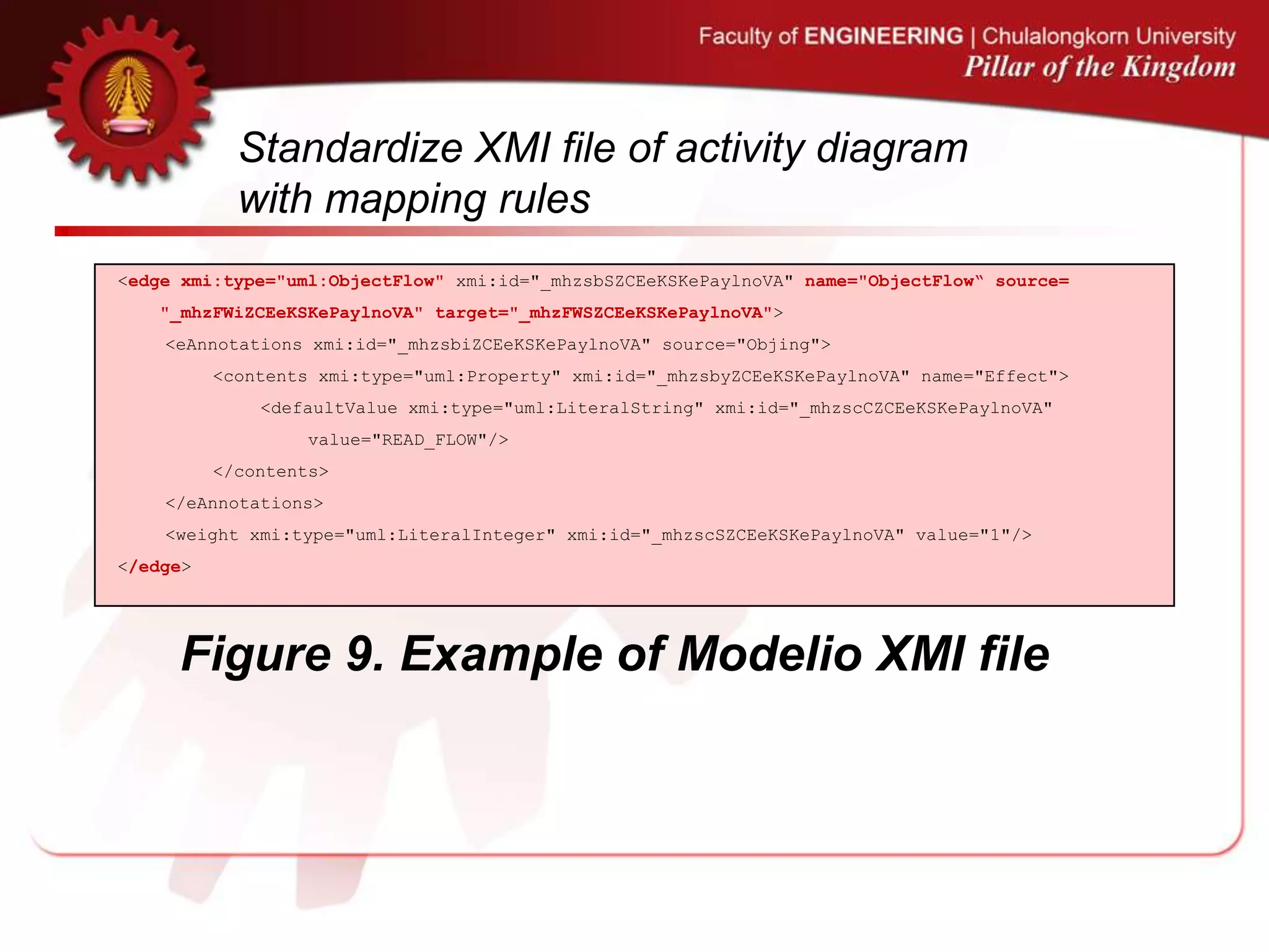
![Standardize XMI file of activity diagram
with mapping rules
• The input of the system is the XMI file of the
UML activity diagram to be reviewed.
• Since different UML tools support different XMI
formats and the UML notations may vary due
to enhanced version, the XMI standard
converter is therefore developed in this work.
• The component is responsible for converting
the XMI format of the input activity diagram to
the defined XMI format.
[5] C. Narkngam, Y. Limpiyakorn, “Rendering UML Activity Diagrams as a Domain Specific Language - ADL”. th International Conference on Software Engineering and Knowledge Engineering, (2012),
July 1-3; San Francisco, USA.
[6] C. Narkngam, Y. Limpiyakorn, “Designing a Domain Specific Language for UML Activity Diagram”. 4th International Conference on Computer Engineering and Technology, (2012), May 12-13; Bangkok, Thailand.
[7] C. Narkngam and Y. Limpiyakorn, “Domain Specific Language for Activity Diagram”, Ramkhamhaeng Journal of Engineering, vol. 1, (2012).](https://image.slidesharecdn.com/extendadlpresentationenv-130710015318-phpapp01/75/Enhancement-of-Action-Description-Language-for-UML-Activity-Diagram-Review-24-2048.jpg)
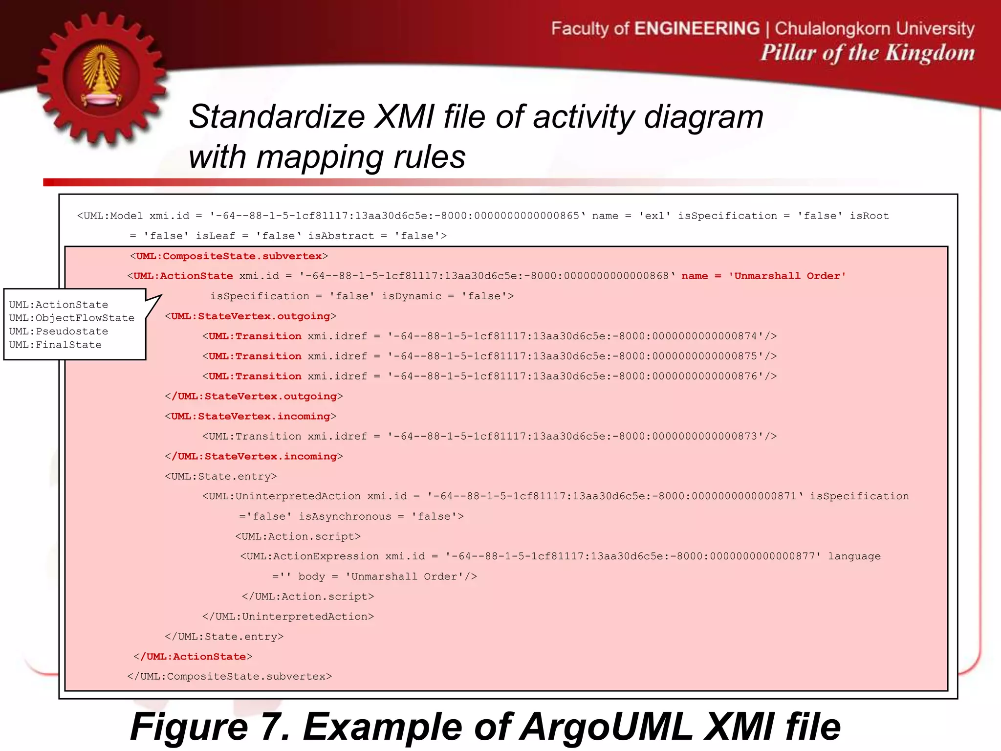
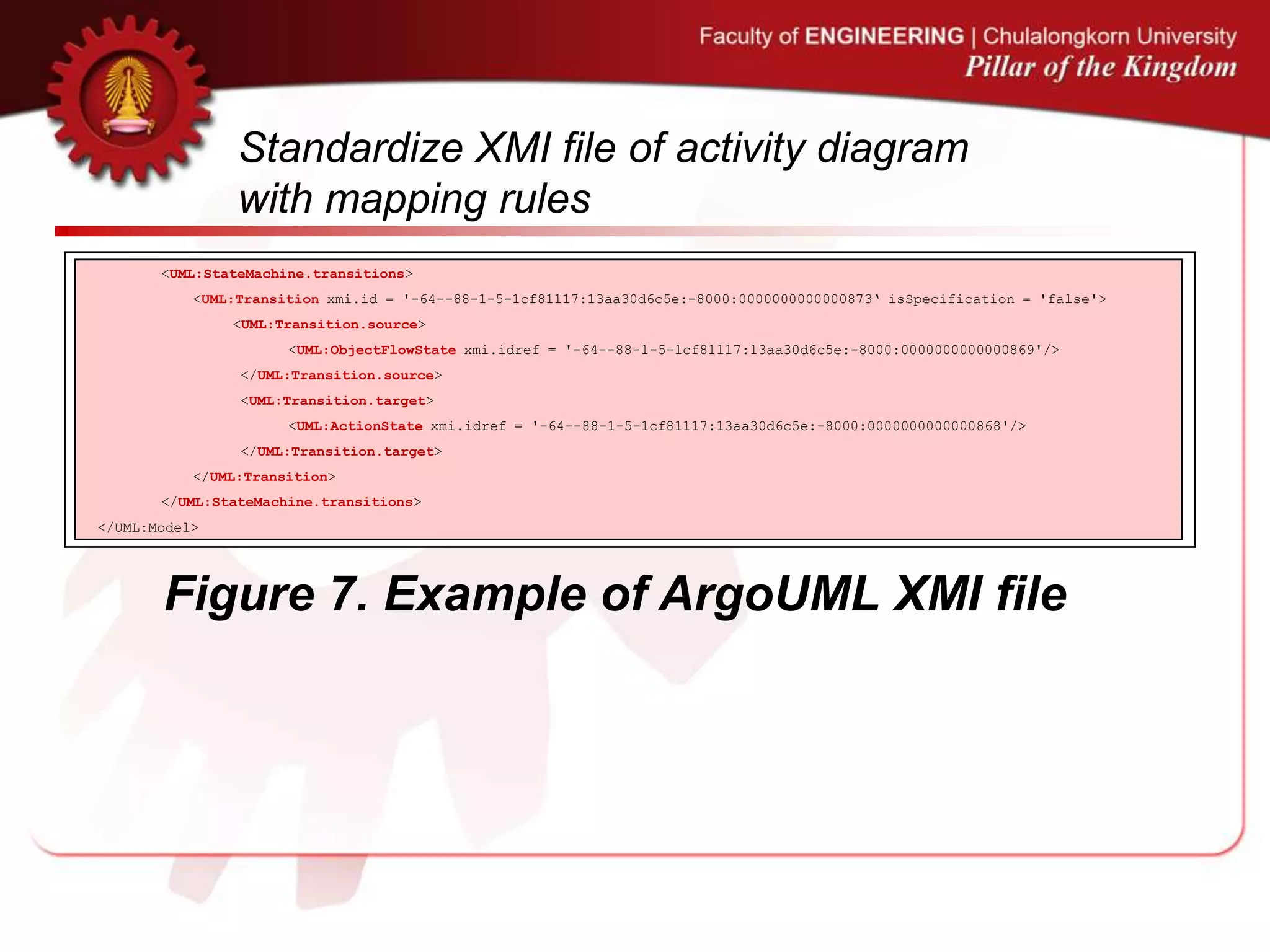
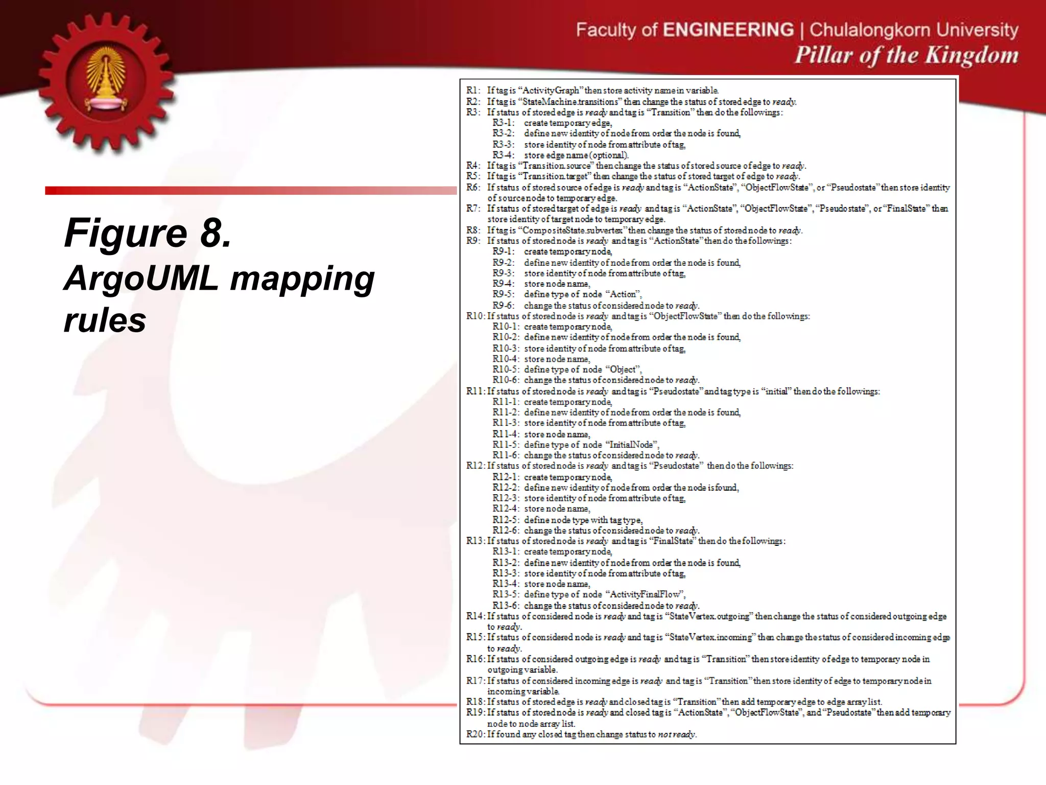
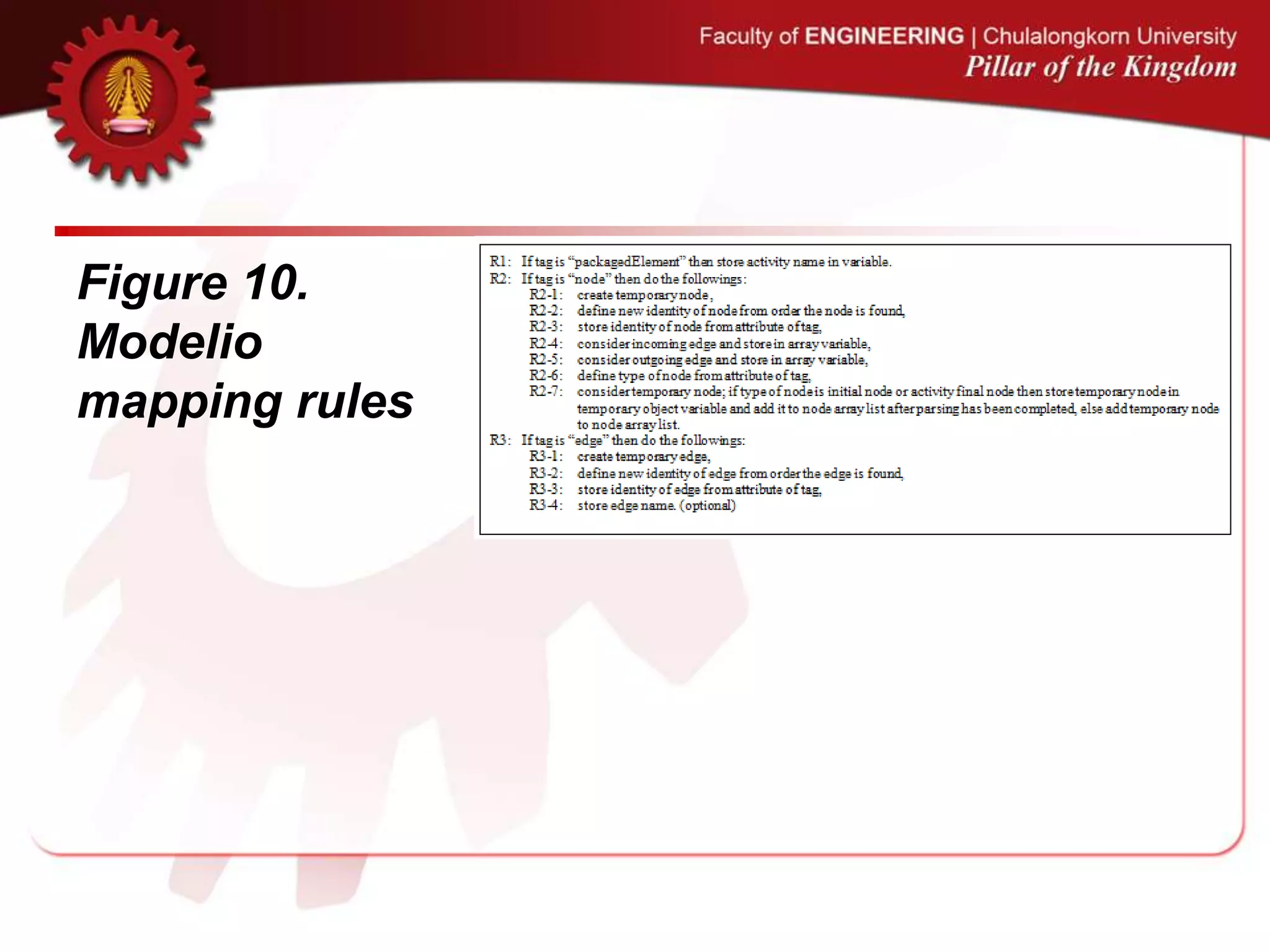
![Standardize XMI file of activity diagram
with mapping rules
• The converter is developed as Eclipse Plug-in
and it uses mapping rules for standardization.
• The mapping rules are particularly defined for
converting the XMI format of ArgoUML and
Modelio.
[5] C. Narkngam, Y. Limpiyakorn, “Rendering UML Activity Diagrams as a Domain Specific Language - ADL”. th International Conference on Software Engineering and Knowledge Engineering, (2012),
July 1-3; San Francisco, USA.
[6] C. Narkngam, Y. Limpiyakorn, “Designing a Domain Specific Language for UML Activity Diagram”. 4th International Conference on Computer Engineering and Technology, (2012), May 12-13; Bangkok, Thailand.
[7] C. Narkngam and Y. Limpiyakorn, “Domain Specific Language for Activity Diagram”, Ramkhamhaeng Journal of Engineering, vol. 1, (2012).](https://image.slidesharecdn.com/extendadlpresentationenv-130710015318-phpapp01/75/Enhancement-of-Action-Description-Language-for-UML-Activity-Diagram-Review-25-2048.jpg)

![2. Generate ADL
Script
1 Standardize
XMI file of activity
diagram with mapping
rules
Activity diagram in
XMI format
Standardized XMI-
formatted activity
diagram
2. Generate
ADL script
ADL script
3.Verify &
Generate
inspection report
Intermediate activity
diagram metamodel
Java ANTLR grammar
Inspection result
UML 2.4.1 constraints
ADL semantic model
4. Parse ADL
script
[conform with UML]
[not conform with UML]
Valid ADL script
ADL metamodel
ADL ANTLR
grammar](https://image.slidesharecdn.com/extendadlpresentationenv-130710015318-phpapp01/75/Enhancement-of-Action-Description-Language-for-UML-Activity-Diagram-Review-36-2048.jpg)
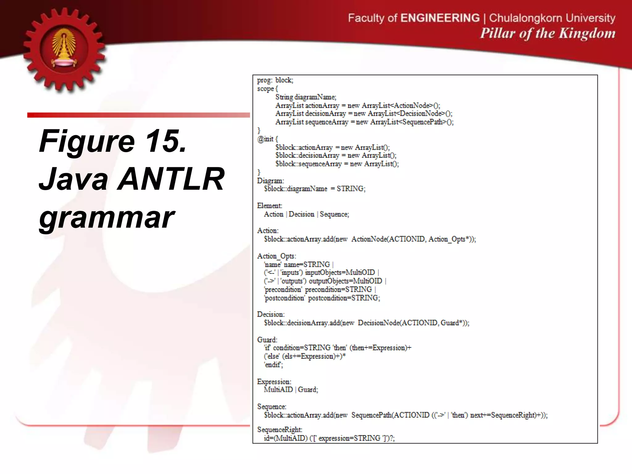
![Generate ADL Script
• The second step is to transform the XMI standard
document obtained from the previous step into the ADL
script.
• The method is to reverse the approach presented in [5],
[6], [7].
• If the resulting ADL script fails during the verification in
the next step, it can be accessed and revised.
[5] C. Narkngam, Y. Limpiyakorn, “Rendering UML Activity Diagrams as a Domain Specific Language - ADL”. th International Conference on Software Engineering and Knowledge Engineering, (2012),
July 1-3; San Francisco, USA.
[6] C. Narkngam, Y. Limpiyakorn, “Designing a Domain Specific Language for UML Activity Diagram”. 4th International Conference on Computer Engineering and Technology, (2012), May 12-13; Bangkok, Thailand.
[7] C. Narkngam and Y. Limpiyakorn, “Domain Specific Language for Activity Diagram”, Ramkhamhaeng Journal of Engineering, vol. 1, (2012).](https://image.slidesharecdn.com/extendadlpresentationenv-130710015318-phpapp01/75/Enhancement-of-Action-Description-Language-for-UML-Activity-Diagram-Review-37-2048.jpg)
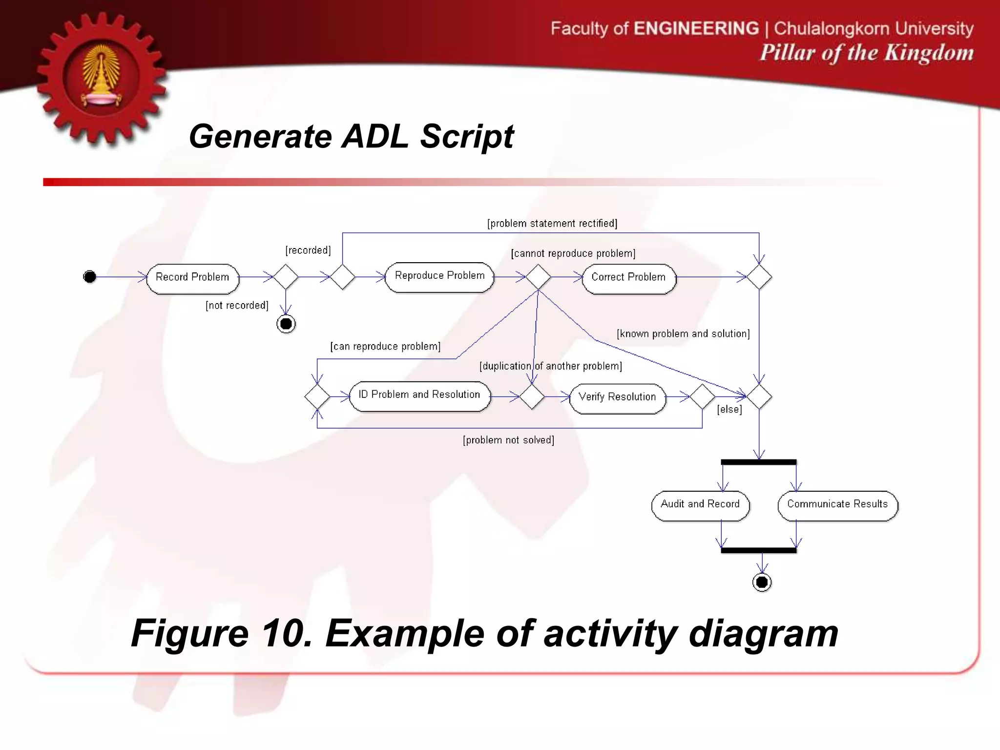
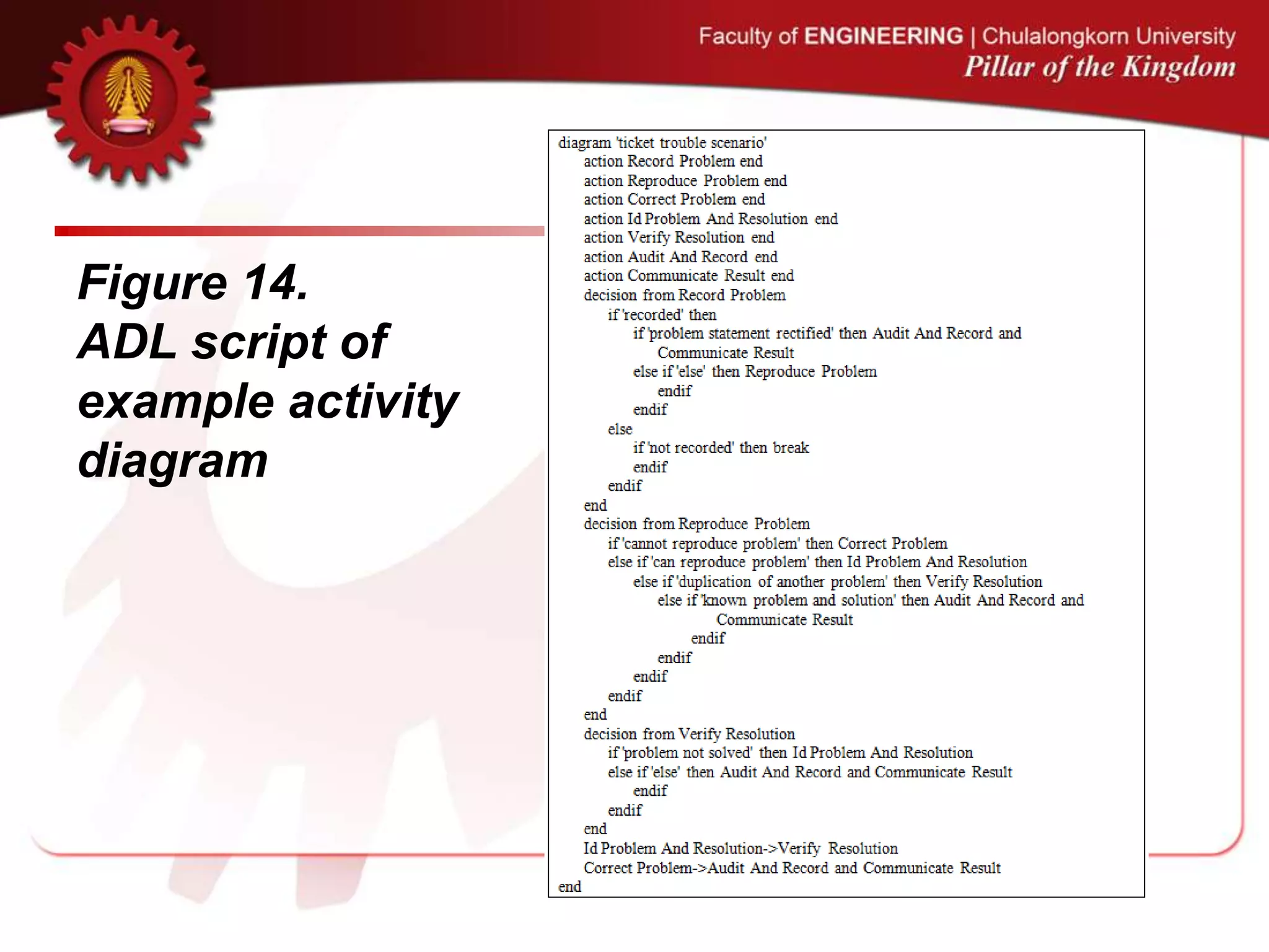
![Generate ADL Script
• The initial step of ADL script generation is to parse the
XMI standard document obtained from the previous step
to node and edge array lists.
• Next, the ADL script generator will inspect node/edge
and generate the script based on each item.
• The following three steps are carried out during the
script generation.
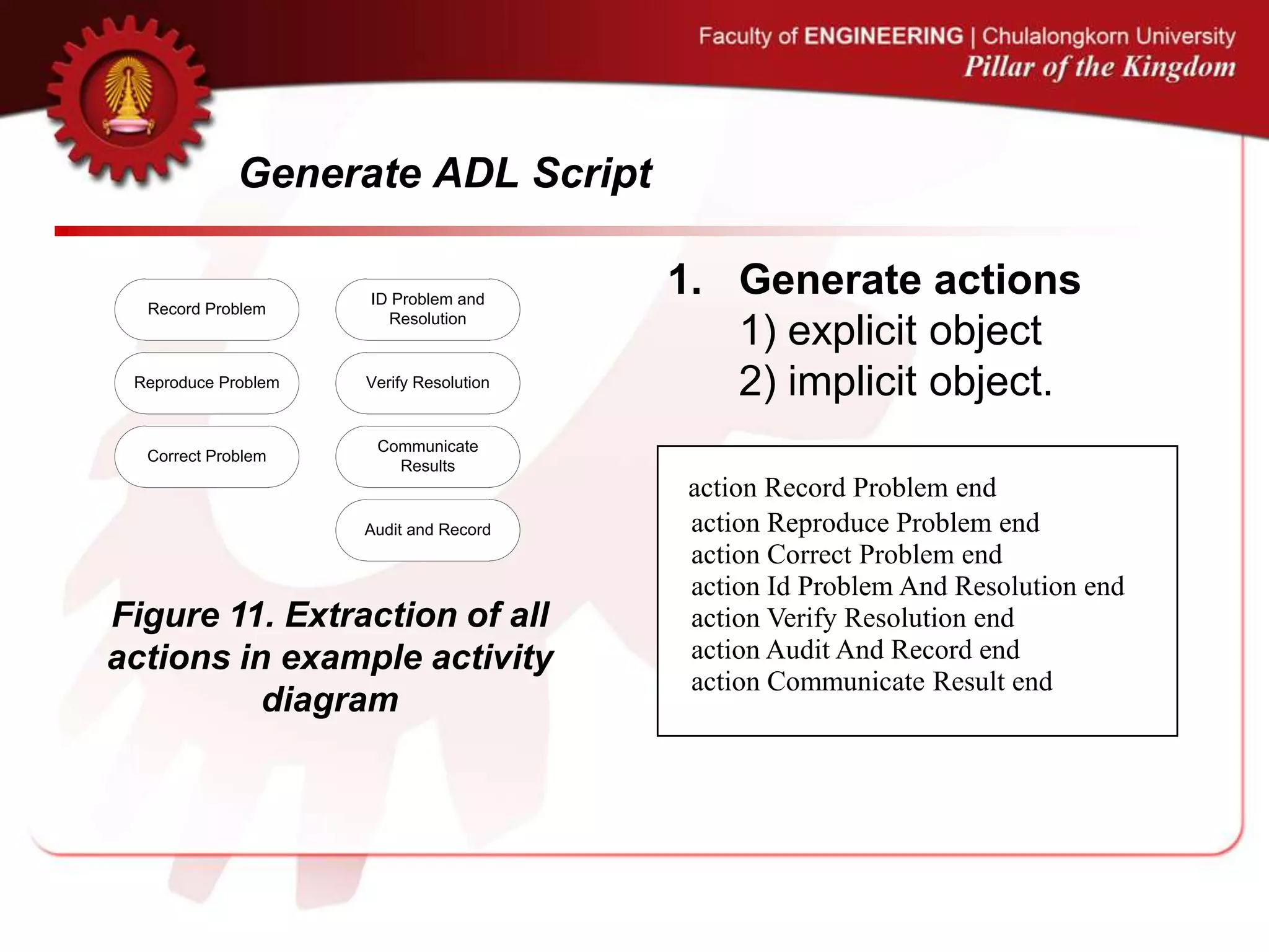
1. Generate actions.
2. Generate decisions.
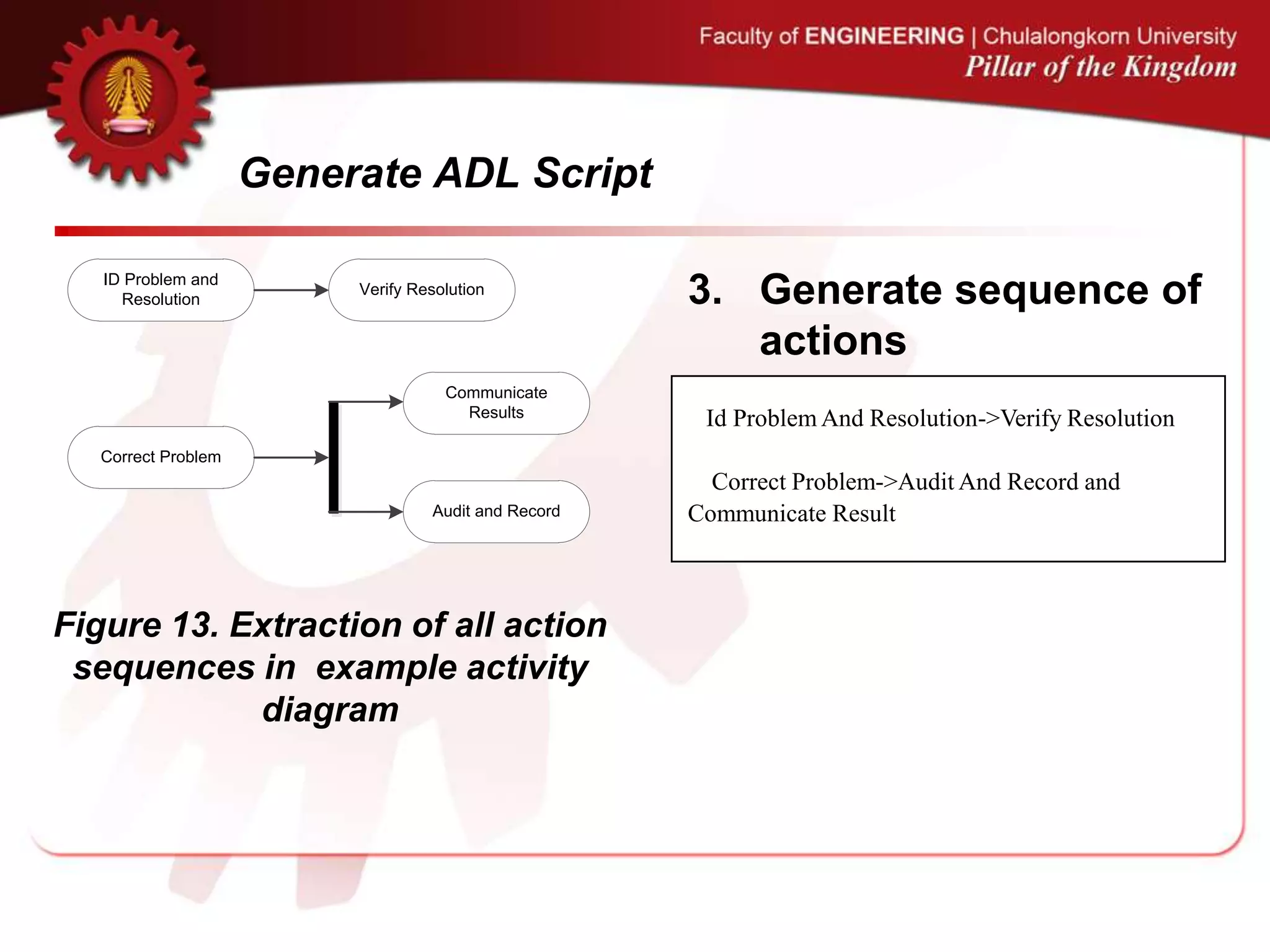
3. Generate sequence of actions.
[5] C. Narkngam, Y. Limpiyakorn, “Rendering UML Activity Diagrams as a Domain Specific Language - ADL”. th International Conference on Software Engineering and Knowledge Engineering, (2012),
July 1-3; San Francisco, USA.
[6] C. Narkngam, Y. Limpiyakorn, “Designing a Domain Specific Language for UML Activity Diagram”. 4th International Conference on Computer Engineering and Technology, (2012), May 12-13; Bangkok, Thailand.
[7] C. Narkngam and Y. Limpiyakorn, “Domain Specific Language for Activity Diagram”, Ramkhamhaeng Journal of Engineering, vol. 1, (2012).](https://image.slidesharecdn.com/extendadlpresentationenv-130710015318-phpapp01/75/Enhancement-of-Action-Description-Language-for-UML-Activity-Diagram-Review-38-2048.jpg)
![Generate ADL Script
Record Problem Reproduce Problem
[not recorded]
[recorded]
[problem statement rectified]
[else]
Correct Problem
ID Problem and
Resolution
Verify Resolution
[cannot
reproduce
problem]
[can reproduce
problem]
[duplication of another problem
[known problem and solution]
ID Problem and
Resolution
Verify Resolution
[else]
[problem not solved]
2. Generate decisions
decision from Record Problem
if 'recorded' then
if 'problem statement rectified' then
Audit And Record and Communicate Result
else if 'else' then Reproduce Problem
endif
endif
else
if 'not recorded' then break
endif
endif
end
Figure 12. Extraction of all
decisions in example activity
diagram](https://image.slidesharecdn.com/extendadlpresentationenv-130710015318-phpapp01/75/Enhancement-of-Action-Description-Language-for-UML-Activity-Diagram-Review-41-2048.jpg)
![Generate ADL Script
Record Problem Reproduce Problem
[not recorded]
[recorded]
[problem statement rectified]
[else]
Correct Problem
ID Problem and
Resolution
Verify Resolution
[cannot
reproduce
problem]
[can reproduce
problem]
[duplication of another problem
[known problem and solution]
ID Problem and
Resolution
Verify Resolution
[else]
[problem not solved]
2. Generate decisions
decision from Reproduce Problem
if 'cannot reproduce problem' then
Correct Problem
else if 'can reproduce problem' then
Id Problem And Resolution
else if 'duplication of another problem' then
Verify Resolution
else if 'known problem and solution' then
Audit And Record and Communicate
Result
endif
endif
endif
endif
end
Figure 12. Extraction of all
decisions in example activity
diagram](https://image.slidesharecdn.com/extendadlpresentationenv-130710015318-phpapp01/75/Enhancement-of-Action-Description-Language-for-UML-Activity-Diagram-Review-42-2048.jpg)
![Generate ADL Script
Record Problem Reproduce Problem
[not recorded]
[recorded]
[problem statement rectified]
[else]
Correct Problem
ID Problem and
Resolution
Verify Resolution
[cannot
reproduce
problem]
[can reproduce
problem]
[duplication of another problem
[known problem and solution]
ID Problem and
Resolution
Verify Resolution
[else]
[problem not solved]
2. Generate decisions
decision from Verify Resolution
if 'problem not solved' then
Id Problem And Resolution
else if 'else' then Audit And Record and
Communicate Result
endif
endif
end
Figure 12. Extraction of all
decisions in example activity
diagram](https://image.slidesharecdn.com/extendadlpresentationenv-130710015318-phpapp01/75/Enhancement-of-Action-Description-Language-for-UML-Activity-Diagram-Review-43-2048.jpg)
![3. Verify and
Generate
Inspection
Result
1 Standardize
XMI file of activity
diagram with mapping
rules
Activity diagram in
XMI format
Standardized XMI-
formatted activity
diagram
2. Generate
ADL script
ADL script
3.Verify &
Generate
inspection report
Intermediate activity
diagram metamodel
Java ANTLR grammar
Inspection result
UML 2.4.1 constraints
ADL semantic model
4. Parse ADL
script
[conform with UML]
[not conform with UML]
Valid ADL script
ADL metamodel
ADL ANTLR
grammar](https://image.slidesharecdn.com/extendadlpresentationenv-130710015318-phpapp01/75/Enhancement-of-Action-Description-Language-for-UML-Activity-Diagram-Review-46-2048.jpg)
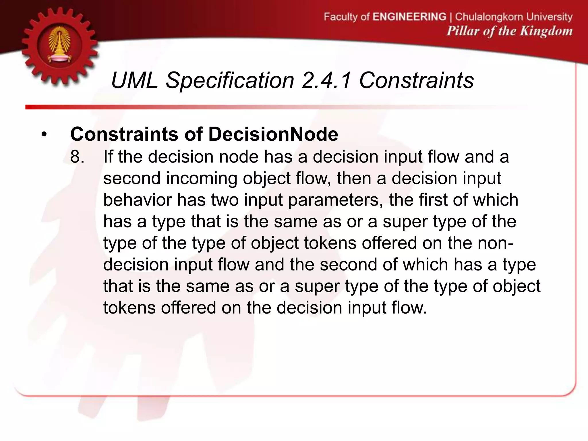
![UML Specification 2.4.1 Constraints
• Constraints of DecisionNode
1. A decision node has one or two incoming edges and at
least one outgoing edge.
2. The edges coming into and out of a decision node, other
than the decision input flow (if any), must be either all
object flows or all control flows.
3. The decisionInputFlow [2] of a decision node must be an
incoming edge of the decision node.
4. A decision input behavior has no output parameters, no
in-out parameters and one return parameter.
5. If the decision node has no decision input flow and an
incoming control flow, then a decision input behavior has
zero input parameters.](https://image.slidesharecdn.com/extendadlpresentationenv-130710015318-phpapp01/75/Enhancement-of-Action-Description-Language-for-UML-Activity-Diagram-Review-54-2048.jpg)

![4. Parse ADL
Script
1 Standardize
XMI file of activity
diagram with mapping
rules
Activity diagram in
XMI format
Standardized XMI-
formatted activity
diagram
2. Generate
ADL script
ADL script
3.Verify &
Generate
inspection report
Intermediate activity
diagram metamodel
Java ANTLR grammar
Inspection result
UML 2.4.1 constraints
ADL semantic model
4. Parse ADL
script
[conform with UML]
[not conform with UML]
Valid ADL script
ADL metamodel
ADL ANTLR
grammar](https://image.slidesharecdn.com/extendadlpresentationenv-130710015318-phpapp01/75/Enhancement-of-Action-Description-Language-for-UML-Activity-Diagram-Review-59-2048.jpg)


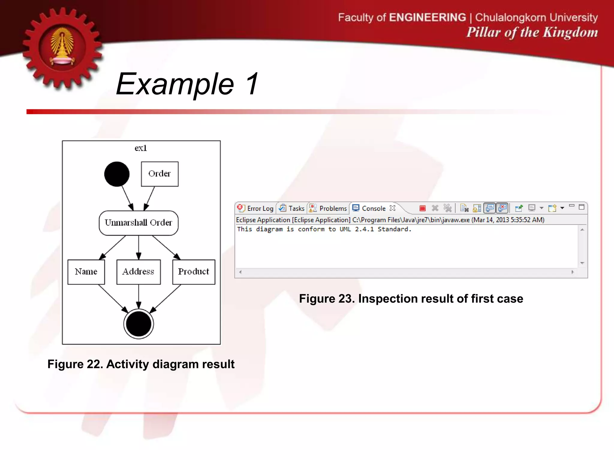
![Example 1
Figure 18. First case of examined
activity diagram created by ArgoUML
Figure 19. First case of examined
activity diagram created by Modelio
Figure 20. ADL script from [10] Figure 21. ADL script result
[10] . .
,](https://image.slidesharecdn.com/extendadlpresentationenv-130710015318-phpapp01/75/Enhancement-of-Action-Description-Language-for-UML-Activity-Diagram-Review-64-2048.jpg)
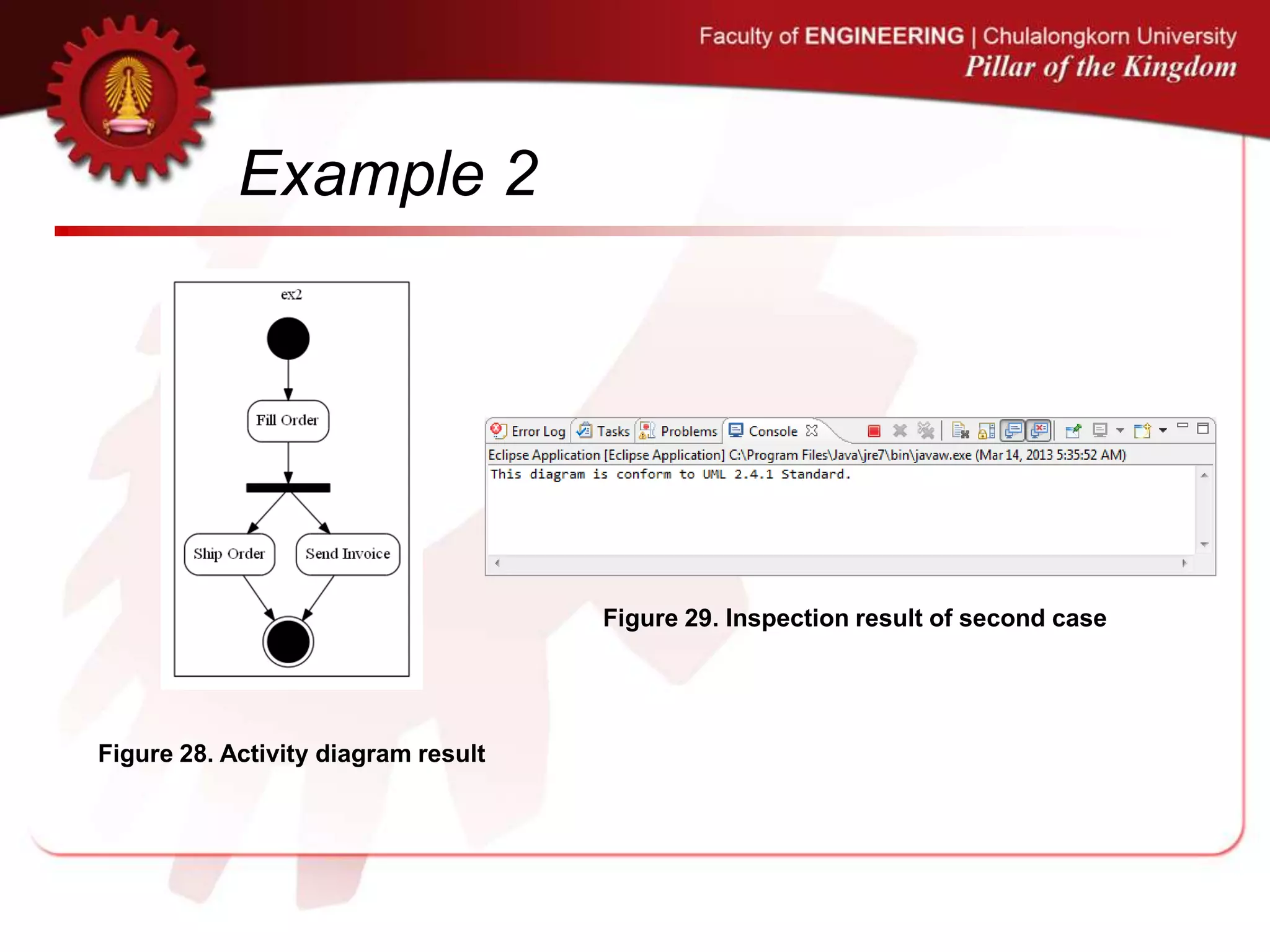
![Example 2
Figure 24. Second case of examined
activity diagram created by ArgoUML
Figure 25. Second case of examined
activity diagram created by Modelio
Figure 26. ADL script from [10] Figure 27. ADL script result
[10] . .
,](https://image.slidesharecdn.com/extendadlpresentationenv-130710015318-phpapp01/75/Enhancement-of-Action-Description-Language-for-UML-Activity-Diagram-Review-66-2048.jpg)
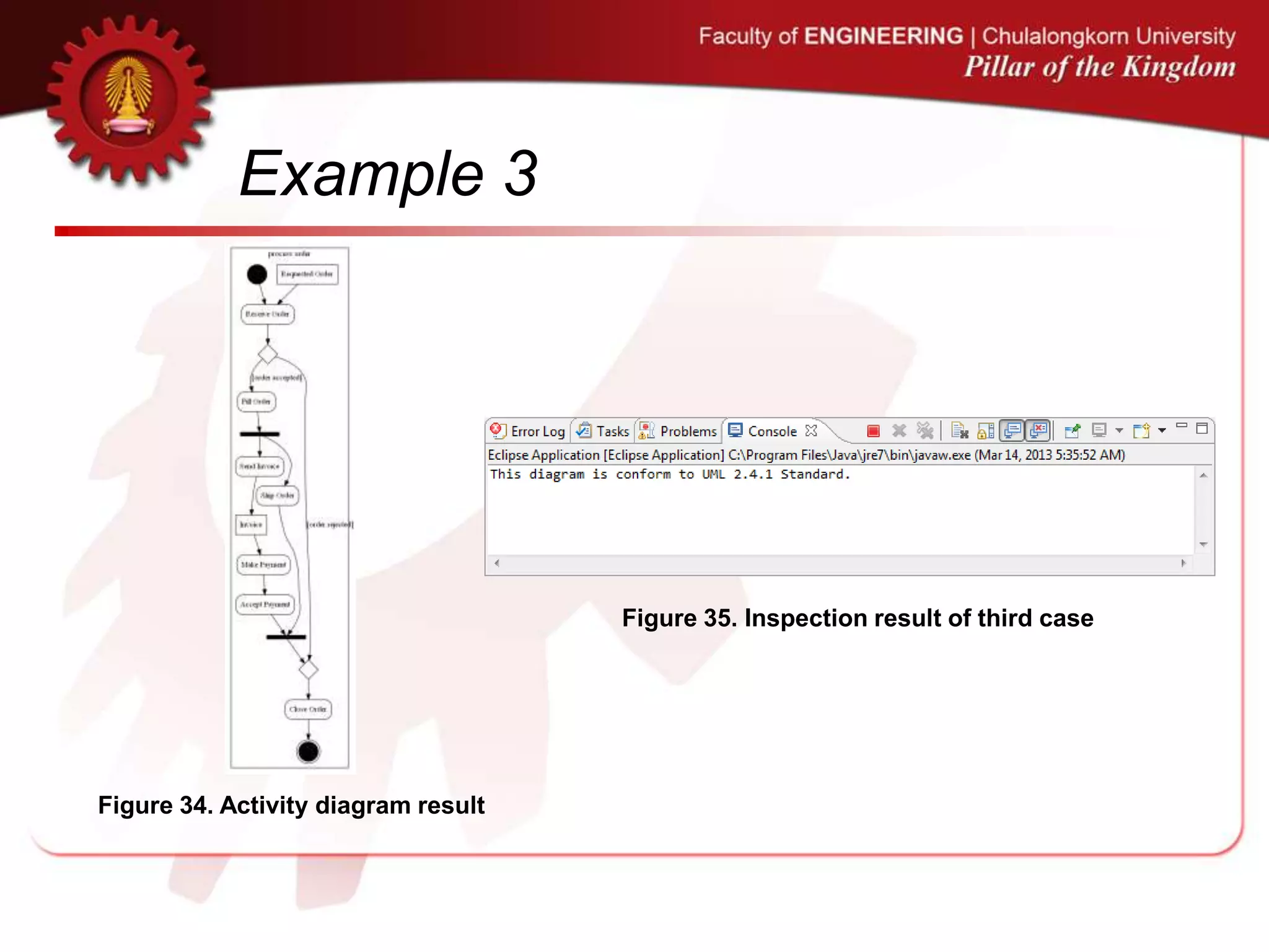
![Example 3
Figure 30. Third case of examined
activity diagram created by ArgoUML
Figure 31. Third case of examined
activity diagram created by Modelio
[10] . .
,](https://image.slidesharecdn.com/extendadlpresentationenv-130710015318-phpapp01/75/Enhancement-of-Action-Description-Language-for-UML-Activity-Diagram-Review-68-2048.jpg)
![Example 3
Figure 32. ADL script from [10]
Figure 33. ADL script result
[10] . .
,](https://image.slidesharecdn.com/extendadlpresentationenv-130710015318-phpapp01/75/Enhancement-of-Action-Description-Language-for-UML-Activity-Diagram-Review-69-2048.jpg)
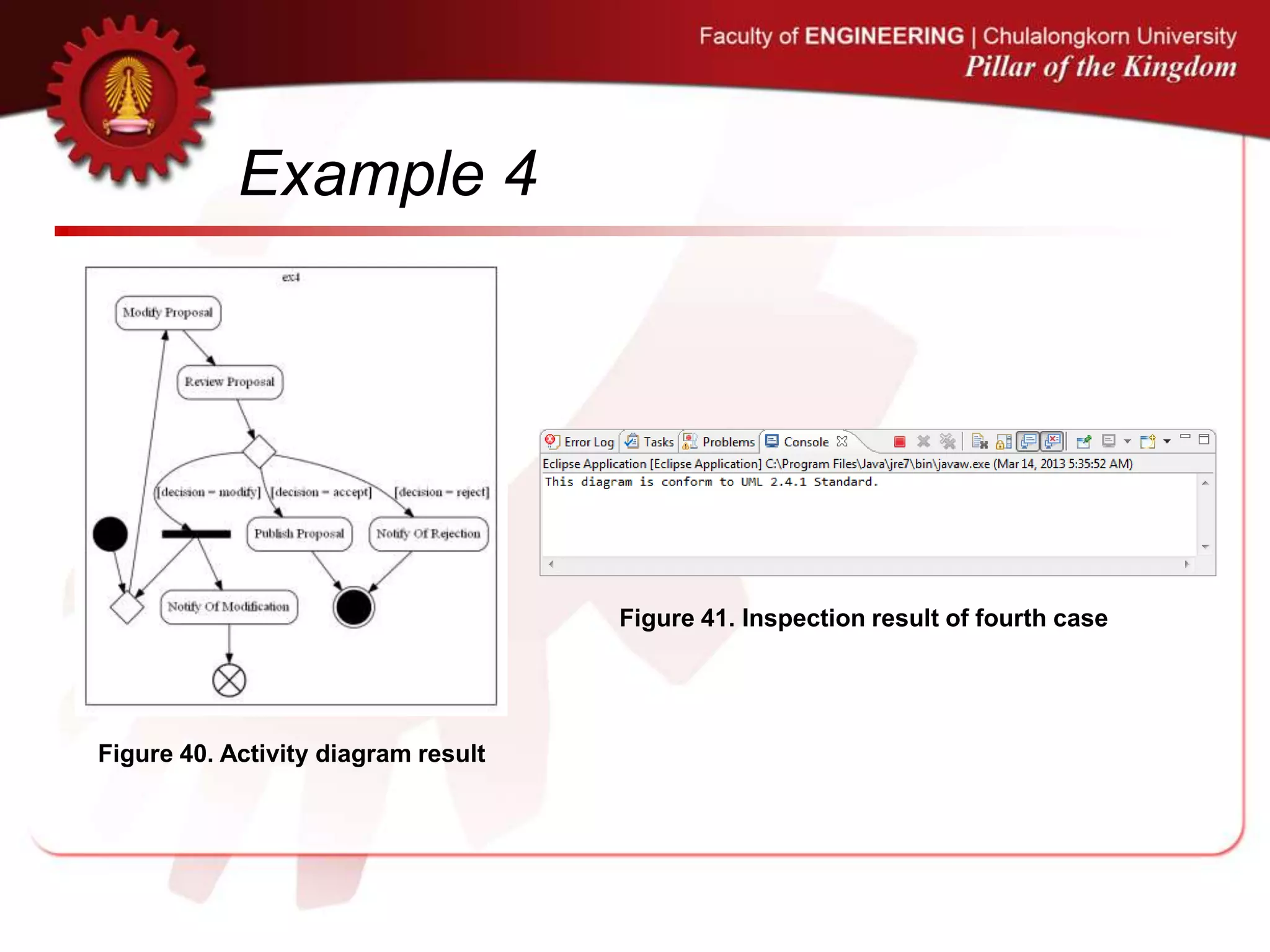
![Example 4
Figure 36. Fourth case of examined
activity diagram created by ArgoUML
Figure 37. Fourth case of examined
activity diagram created by Modelio
[10] . .
,](https://image.slidesharecdn.com/extendadlpresentationenv-130710015318-phpapp01/75/Enhancement-of-Action-Description-Language-for-UML-Activity-Diagram-Review-71-2048.jpg)
![Example 4
Figure 38. ADL script from [10] Figure 39. ADL script result
[10] . .
,](https://image.slidesharecdn.com/extendadlpresentationenv-130710015318-phpapp01/75/Enhancement-of-Action-Description-Language-for-UML-Activity-Diagram-Review-72-2048.jpg)
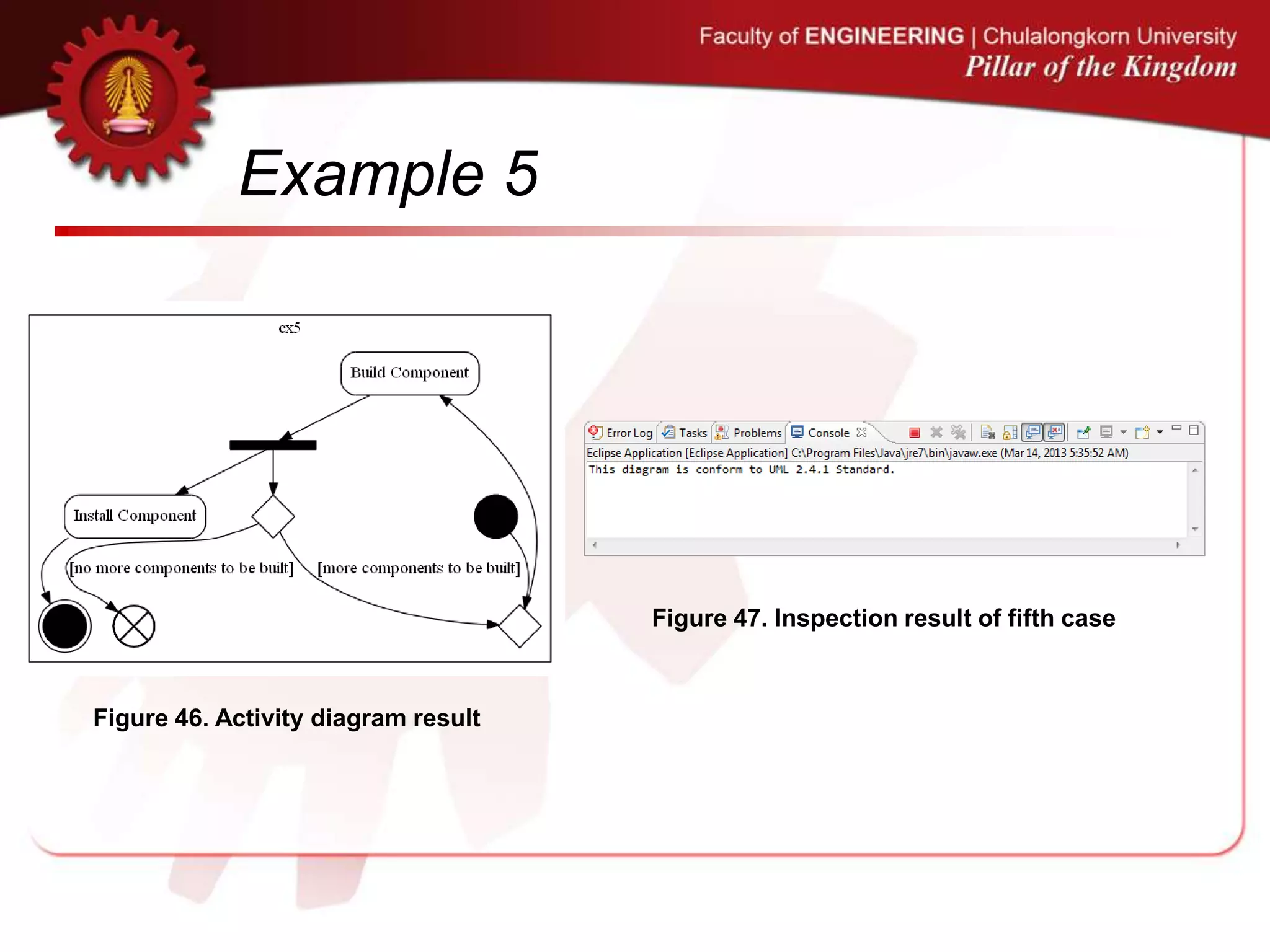
![Example 5
Figure 42. Fifth case of examined
activity diagram created by ArgoUML
Figure 43. Fifth case of examined
activity diagram created by Modelio
Figure 44. ADL script from [10] Figure 45. ADL script result
[10] . .
,](https://image.slidesharecdn.com/extendadlpresentationenv-130710015318-phpapp01/75/Enhancement-of-Action-Description-Language-for-UML-Activity-Diagram-Review-74-2048.jpg)
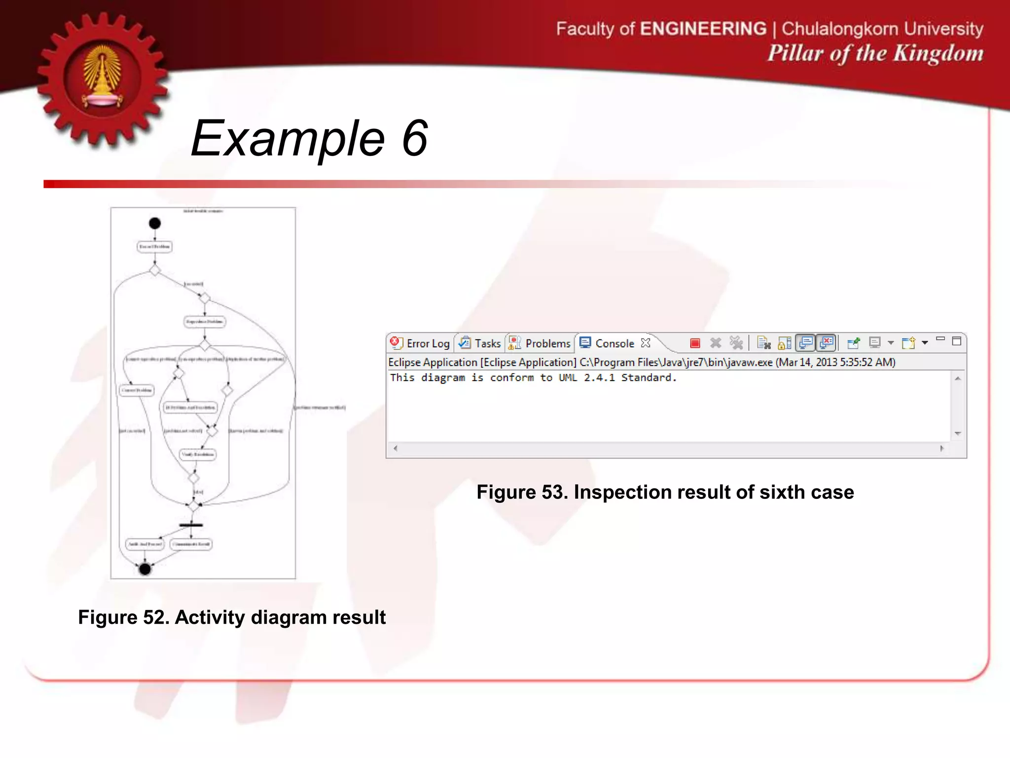
![Example 6
Figure 48. Sixth case of examined
activity diagram created by ArgoUML
Figure 49. Sixth case of examined
activity diagram created by Modelio
[10] . .
,](https://image.slidesharecdn.com/extendadlpresentationenv-130710015318-phpapp01/75/Enhancement-of-Action-Description-Language-for-UML-Activity-Diagram-Review-76-2048.jpg)
![Example 6
Figure 50. ADL script from [10] Figure 51. ADL script result
[10] . .
,](https://image.slidesharecdn.com/extendadlpresentationenv-130710015318-phpapp01/75/Enhancement-of-Action-Description-Language-for-UML-Activity-Diagram-Review-77-2048.jpg)
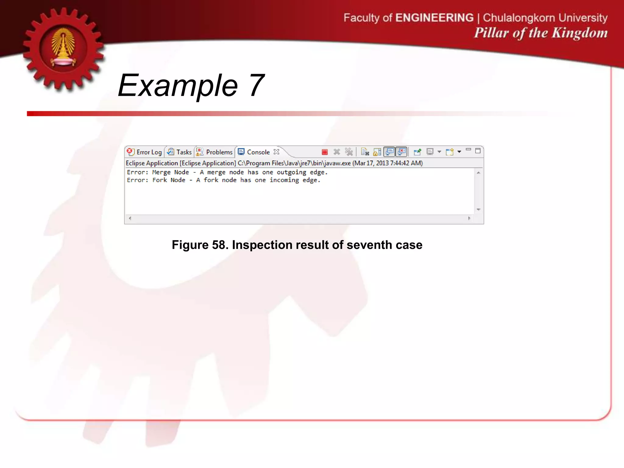
![Example 7
Figure 54. Seventh case of examined
activity diagram created by ArgoUML
Figure 55. Seventh case of examined
activity diagram created by Modelio
Figure 56. ADL script from [10] Figure 57. ADL script result
[10] . .
,](https://image.slidesharecdn.com/extendadlpresentationenv-130710015318-phpapp01/75/Enhancement-of-Action-Description-Language-for-UML-Activity-Diagram-Review-79-2048.jpg)
![Example 8
Figure 59. Eighth case of examined
activity diagram created by ArgoUML
Figure 60. Eighth case of examined
activity diagram created by Modelio
[10] . .
,](https://image.slidesharecdn.com/extendadlpresentationenv-130710015318-phpapp01/75/Enhancement-of-Action-Description-Language-for-UML-Activity-Diagram-Review-81-2048.jpg)
![Example 8
Figure 61. ADL script from [10] Figure 62. ADL script result
[10] . .
,
Figure 63. Inspection result of eighth case](https://image.slidesharecdn.com/extendadlpresentationenv-130710015318-phpapp01/75/Enhancement-of-Action-Description-Language-for-UML-Activity-Diagram-Review-82-2048.jpg)

![Conclusion
• This research thus presents an automation
approach to reviewing the UML activity
diagrams.
• The method deploys a domain specific
language called Action Description Language
(ADL) created in [5], [6], [7].
• In this work, we have enhanced ADL for
reviewing the existing activity diagrams
whether they conform to UML specification
v.2.4.1.
[5] C. Narkngam, Y. Limpiyakorn, “Rendering UML Activity Diagrams as a Domain Specific Language - ADL”. th International Conference on Software Engineering and Knowledge Engineering, (2012),
July 1-3; San Francisco, USA.
[6] C. Narkngam, Y. Limpiyakorn, “Designing a Domain Specific Language for UML Activity Diagram”. 4th International Conference on Computer Engineering and Technology, (2012), May 12-13; Bangkok, Thailand.
[7] C. Narkngam and Y. Limpiyakorn, “Domain Specific Language for Activity Diagram”, Ramkhamhaeng Journal of Engineering, vol. 1, (2012).](https://image.slidesharecdn.com/extendadlpresentationenv-130710015318-phpapp01/75/Enhancement-of-Action-Description-Language-for-UML-Activity-Diagram-Review-85-2048.jpg)
![Conclusion
• The proposed method can be considered as
the reverse of the research work [5], [6], [7],
which generates UML activity diagrams from
ADL scripts.
• Conversely, this research generates ADL
scripts from existing activity diagrams.
[5] C. Narkngam, Y. Limpiyakorn, “Rendering UML Activity Diagrams as a Domain Specific Language - ADL”. th International Conference on Software Engineering and Knowledge Engineering, (2012),
July 1-3; San Francisco, USA.
[6] C. Narkngam, Y. Limpiyakorn, “Designing a Domain Specific Language for UML Activity Diagram”. 4th International Conference on Computer Engineering and Technology, (2012), May 12-13; Bangkok, Thailand.
[7] C. Narkngam and Y. Limpiyakorn, “Domain Specific Language for Activity Diagram”, Ramkhamhaeng Journal of Engineering, vol. 1, (2012).](https://image.slidesharecdn.com/extendadlpresentationenv-130710015318-phpapp01/75/Enhancement-of-Action-Description-Language-for-UML-Activity-Diagram-Review-86-2048.jpg)
![Conclusion
• However, the final output obtained from the
proposed approach is the ADL semantic
model, which is useful for further applications,
namely the automated generation of test
cases, design blueprints, and source code.
• Moreover, the ADL scripts obtained from this
work can be used for later modification and
generation of UML activity diagrams as being
processed in the preventive approach
presented in [5], [6], [7].
[5] C. Narkngam, Y. Limpiyakorn, “Rendering UML Activity Diagrams as a Domain Specific Language - ADL”. th International Conference on Software Engineering and Knowledge Engineering, (2012),
July 1-3; San Francisco, USA.
[6] C. Narkngam, Y. Limpiyakorn, “Designing a Domain Specific Language for UML Activity Diagram”. 4th International Conference on Computer Engineering and Technology, (2012), May 12-13; Bangkok, Thailand.
[7] C. Narkngam and Y. Limpiyakorn, “Domain Specific Language for Activity Diagram”, Ramkhamhaeng Journal of Engineering, vol. 1, (2012).](https://image.slidesharecdn.com/extendadlpresentationenv-130710015318-phpapp01/75/Enhancement-of-Action-Description-Language-for-UML-Activity-Diagram-Review-87-2048.jpg)

The document discusses the enhancement of the Action Description Language (ADL) for automating the review of UML activity diagrams to ensure conformity with UML specifications. It outlines problems with manual diagram creation, presents the research solutions, and details a four-step automation review process involving XMI file standardization. The proposed approach aims to improve software development quality by reducing errors and inconsistencies in UML modeling.


![Vibe Coding vs. Spec-Driven Development [Free Meetup]](https://cdn.slidesharecdn.com/ss_thumbnails/vibecodingvsspecdrivendevelopment-251209105622-43f455e7-thumbnail.jpg?width=640&height=640&fit=bounds)


