Downloaded 2,074 times
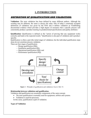


The document provides an overview of pharmaceutical validation and qualification, defining key terms and outlining the relationship between the two concepts. It details various types of process validation, including prospective, concurrent, retrospective, and revalidation, along with their criteria and methodologies. The document emphasizes the importance of a validation master plan (VMP) and user requirement specifications (URS) in ensuring compliance and effective validation processes.