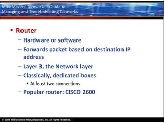
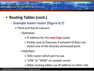
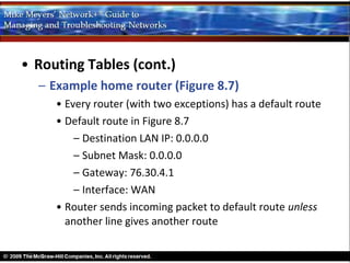
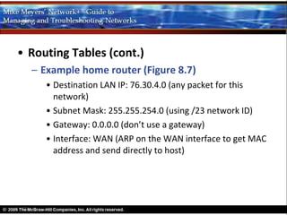
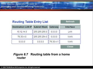
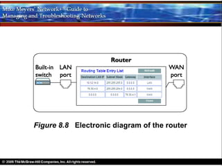
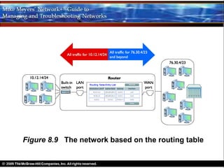
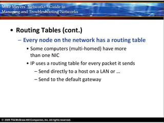
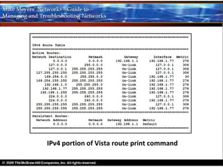
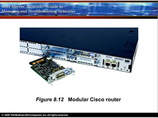
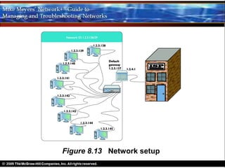
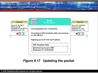
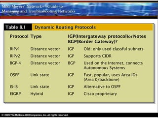
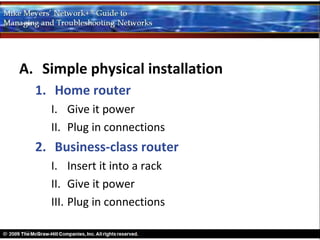
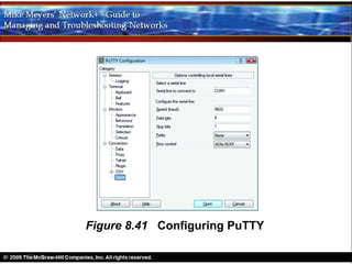
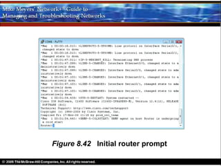
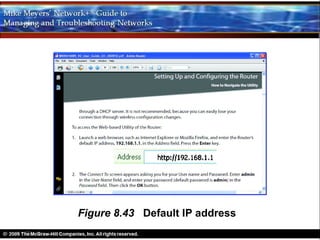
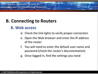
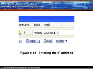
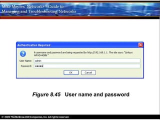
The Wonderful World of Routing


          Chapter 8
Objectives
• Explain how routers work
• Describe dynamic routing technologies
• Install and configure a router successfully
Overview
Three Parts to Chapter 8
• How Routers Work
• Dynamic Routing
• Working with Routers
How Routers Work
• Router
  – Hardware or software
  – Forwards packet based on destination IP
    address
  – Layer 3, the Network layer
  – Classically, dedicated boxes
    • At least two connections
  – Popular router: CISCO 2600
Figure 8.1 Cisco 2611 router
• Home router
  –   First exposure to a router for most techs
  –   Connect PC to DSL receiver or cable modem
  –   More than it appears to be
  –   LAN side may connect internally to a built-in
      switch
Figure 8.2 Business end of a typical home router
Figure 8.3 Cisco router diagram
Figure 8.4 Linksys home router diagram
• All routers
  – Examine packets
  – Send packets to proper destination
• Routing Tables
  – Router strips off Layer 2 information
  – Drops IP packet into a queue
     • Source address is not important
     • Every packet dropped into the same queue based
       on time of arrival
  – Router inspects the destination IP address
  – Router send IP packet out correct port
  – Routing table tells router where to send packets
Figure 8.5 Incoming packets
Figure 8.6 All incoming packets stripped of Layer 2
            data and dropped into a common queue
• Routing Tables (cont.)
  – Example home router (Figure 8.7)
     • Two ports
     • Each row in table defines a single route
     • Each column identifies specific criteria
          – Destination LAN IP
          – Subnet Mask
     • If packet’s network ID matches a Destination LAN IP,
       router uses other information in row to determine
       where to send it
• Routing Tables (cont.)
  – Example home router (Figure 8.7)
     • Third and fourth columns
        – Gateway
            » IP address for the next hop router
            » Packet sent to Gateway if network ID does not
              match one of the directly connected ports
        – Interface
            » Tells router which port to use
            » “LAN” or “WAN” on sample router
            » Other routing tables use IP address or other info
• Routing Tables (cont.)
  – Example home router (Figure 8.7)
     • First Router compares destination IP address to
       every listing in the routing table
     • Then router makes a decision
• Routing Tables (cont.)
  – Example home router (Figure 8.7)
     • Every router (with two exceptions) has a default route
     • Default route in Figure 8.7
         – Destination LAN IP: 0.0.0.0
         – Subnet Mask: 0.0.0.0
         – Gateway: 76.30.4.1
         – Interface: WAN
     • Router sends incoming packet to default route unless
       another line gives another route
• Routing Tables (cont.)
  – Example home router (Figure 8.7)
     • Destination LAN IP: 10.12.14.0 (any packet for this
       network)
     • Subnet Mask: 255.255.255.0 (using /24 network ID)
     • Gateway: 0.0.0.0 (don’t use a gateway)
     • Interface: LAN (ARP on the LAN interface to get MAC
       address and send directly to host)
• Routing Tables (cont.)
  – Example home router (Figure 8.7)
     • Destination LAN IP: 76.30.4.0 (any packet for this
       network)
     • Subnet Mask: 255.255.254.0 (using /23 network ID)
     • Gateway: 0.0.0.0 (don’t use a gateway)
     • Interface: WAN (ARP on the WAN interface to get MAC
       address and send directly to host)
Figure 8.7 Routing table from a home
  router
Figure 8.8 Electronic diagram of the router
Figure 8.9 The network based on the routing table
• Routing Tables (cont.)
  – Every node on the network has a routing table
     • Some computers (multi-homed) have more
       than one NIC
     • IP uses a routing table for every packet it sends
         – Send directly to a host on a LAN or …
         – Send to the default gateway
• Routing Tables (cont.)
  – Computer routing table (next slide)
     • More routes than example home router
     • Computer IP address: 10.12.14.201/24
     • Computer loopback: 127.0.0.1
     • Metric: a relative value defining the “cost” of using a
       route
         – When more than one route to a destination,
           lower metric is used
         – When route with lower metric goes down,
           other route used
Figure 8.10 Two routes to the same network
Figure 8.11 When a route no longer works, the
  router         automatically switches
Routing table on an XP computer connected to Figure 8.7 router
IPv4 portion of Vista route print command
• Freedom from Layer 2
  – Routers can connect different network
    technologies
  – Routers strip off all Layer 2 data
  – Routers can connect almost anything that
    stores IP packets
Figure 8.12 Modular Cisco router
Figure 8.13 Network setup
Figure 8.14 Ports at work
Figure 8.15 Redone network IDs; nodes in the LAN
            use private IP addressees internally
• Inside the router
  – Host 192.168.10.202 sends a packet to 12.43.65.223
  – Packet is sent to the gateway router
  – Router replaces the sending host’s IP with its
    own public IP address
  – Router then adds the destination IP address
    and the source ephemeral port to the
    NAT translation table
  – On receiving response, router reverses the IP
    addresses and ports
Figure 8.16 NATing a packet
Figure 8.17 Updating the packet
• Inside the router (cont.)
  – Router compares incoming destination
    port and source address to entries in NAT
    translation table
  – Determines which local IP address to put
    back on the packet
  – Sends packet to the correct computer on
    the LAN
• Port forwarding
  – Hides a port number from the Internet
  – Enables public servers to work behind a
    NAT router
  – Gives servers the protection of NAT while
    allowing access to a local server from the
    Internet
Dynamic Routing
A. Background
  1. Routers have static routes
    I. Manually entered
    II. Detected at setup by the router
• Background (cont.)
  2. Dynamic routing protocols defined
    I. Routers communicate among themselves
         with change information
    II. Update each other on changes about direct
         connections and distant routers
    III. A passage of a packet through a single router
         is a hop
Figure 8.22 Lots of routers
Figure 8.23 Hopping through a WAN
Dynamic Routing Makes the Internet
  1. Internet depends on dynamic routing for
     self-healing
  2. Manual updating impossible with so many
     routes coming up and going down
Table 8.1     Dynamic Routing Protocols

 Protocol Type                IGP(Intergateway protocol)or Notes
                              BGP(Border Gateway)?
 RIPv1      Distance vector   IGP   Old; only used classful subnets
 RIPv2      Distance vector   IGP   Supports CIDR
 BGP-4      Distance vector   BGP   Used on the Internet, connects
                                    Autonomous Systems
 OSPF       Link state        IGP   Fast, popular, uses Area IDs
                                    (Area 0/backbone)
 IS-IS      Link state        IGP   Alternative to OSPF
 EIGRP      Hybrid            IGP   Cisco proprietary
Working with Routers
A. Simple physical installation
  1. Home router
    I. Give it power
    II. Plug in connections
  2. Business-class router
    I. Insert it into a rack
    II. Give it power
    III. Plug in connections
B. Connecting to Routers
  1. Each router must be configured
  2. Yost cable
    I. Oldest method for connecting to router for
         configuration
    II. Almost unique to Cisco-brand routers
    III. Also called rollover cable
Figure 8.39 Cisco console cable
B. Connecting to Routers
  3. Managed devices include both routers
     and advanced switches that can be
     configured
  4. Plug the rollover into console port on
     Cisco router; plug other end into serial
     port on a PC (may need USB-to-serial
     adapter)
Figure 8.40 Console port
B. Connecting to Routers
  5. Use a terminal emulation program to talk
     to the router from the PC over this
     connection
    I. PuTTY
    II. HyperTerminal
    III. Serial port settings: 9600 baud, 8 data bits,
         1 stop bit, no parity
Figure 8.41 Configuring PuTTY
B. Connecting to Routers
  6. Once connected and running terminal
     emulator
    I. You will see the initial router prompt
    II. On Cisco router, this is the Cisco IOS prompt
    III. Working with IOS commands
       a.   Type enable and press ENTER
       b.   Prompt changes to Router#
       c.   IOS is complex
       d.   Newer CISCO routers will lead you through initial
            configuration for basic setup
Figure 8.42 Initial router prompt
B. Connecting to Routers
  7. Normally, you will access a router
     through Web access or network
     management software (both explored
     next)
  8. Web access
    I. Most routers have a built-in Web server
    II. Can do everything you need to do
B. Connecting to Routers
  8. Web access
    III. Easier than working with Cisco
         command-line IOS
    IV. Web access only works if router has a built-in
         IP address from the factory, or you must
         enable Web interface after assigning an IP
         address to the router
    V. To access the Web interface, you must know
         the IP address
B. Connecting to Routers
  8. Web access
    VI. Most techs use a laptop and a special cable
        (Yost or rollover or crossover) to connect
        directly to router for initial configuration
       a. Know the IP address of the router
       b. Assign to the laptop an IP address with the same
          network ID of the router
       c. Connect to router
Figure 8.43 Default IP address
B. Connecting to Routers
  8. Web access
       d. Check the link lights to verify proper connection
       e. Open the Web browser and enter the IP address
          of the router
       f. You will need to enter the default user name and
          password (check the router’s documentation)
       g. Once logged in, find the settings you need
Figure 8.44 Entering the IP address
Figure 8.45 User name and password
B. Connecting to Routers
  9.
B. Connecting to Routers
  9. Network Management Software
    III. Often a Web site
    IV.Administrators manage network and
         make necessary changes
    V. Proprietary tools (OEM)
      a. By manufacturers of managed devices
      b. Usually very powerful and easy to use
      c. Only work on that OEM’s devices
Figure 8.46 Cisco Network Assistant
B. Connecting to Routers
  9. Network Management Software
    VI.Third-party NMS tools
      a. Some free
      b. Usually harder to configure
      c. Must constantly be updated to work with as
         many devices as possible
      d. Usually lack the amount of detail in an OEM
         NMS
B. Connecting to Routers
  9.Network Management Software
    VI.Third-party NMS tools
      e. While CiscoWorks enables you to change the
         IP address of a port, third-party tools only let
         you see the IP settings
      f. OpenNMS is a popular open-source NMS
Figure 8.47 OpenNMS
B. Connecting to Routers
  10.Other connection methods
    I. Most routers have more than one way
        to connect
    II. Home router may come with a USB port
        and configuration software
      a. More powerful routers may allow connection
         with Telnet protocol or newer Secure Shell
         (SSH)
B. Connecting to Routers
  10.Other connection methods
      a. Terminal emulations protocols that look like
         the terminal emulators seen earlier, but that
         use the network rather than a serial cable
      b. More on terminal emulators in Chapter 9,
         “TCP/IP Applications”
C.                         Basic Router
                           Configuration
     1.Must have at least two connections
     2.You must properly configure every port on

     3.Make sure the routing table sends packets
C. Basic Router Configuration
  4. STEP 1: Set up the WAN side
    I. WAN side in home or small business router
         connects to an ISP
    II. Get setup information from ISP
    III. Most home routers use DHCP on the WAN
         side and just need to be configured to use
         DHCP
C. Basic Router Configuration
  4. STEP 1: Set up the WAN side
    i. May need to enter a static address
    ii. You can buy a single static IP address
    iii. If static address, ISP will tell you what to
         enter into the router
Figure 8.48 The setup
Figure 8.49 WAN router setup
C. Basic Router Configuration
  5. STEP 2: Set up the LAN
    I.                        You usually have
                              total control over the

                              LAN side
    II.                       Choose a network ID
                              from the private
                              range
    III.                      Assign the correct IP
Figure 8.50 Entering a static IP
Figure 8.51 Setting up an IP address for LAN side
C. Basic Router Configuration
  6. STEP 3: Establish routes
    I. Router will usually build a routing table based
         on information you provided
    II. You may add more routes if needed
    III. Use IOS command line on Cisco routers
C. Basic Router Configuration
  7. STEP 4 (Optional): Configure a Dynamic
     Protocol
    I. Dynamic routing protocols tied to
        individual NICs
    II. When you connect two routers together,
        make sure the NICs are configured to use
        the same dynamic routing protocol
C. Basic Router Configuration
  7. STEP 4 (Optional): Configure a Dynamic
     Protocol
    III. Unless you are in charge of two or more
         routers, you will never use a dynamic
         routing protocol
    IV. Once a dynamic routing protocol is turned
         on, it is all automatic
C. Basic Router Configuration
  8. Document and back up
    I.Document what you’ve done to configure each

    II.Back up the configuration using whatever
D. Router Problems
  1.Consider non-router issues first, because

    I. Check NICs, computer, and switches
        before router
    II. Routers are more reliable than other
        equipment
D. Router Problems
  2. Keep in mind what your router is
     supposed to do
    I. Does it just route traffic?
    II. Does it also perform NAT?
    III. Is routing failing, or is another function
         of the router failing?
D. Router Problems
  3. Know how to use a few basic tools
     that can help you check the router
    I. TRACEROUTE
       a. Records the route between any two hosts
       b. Like PING, it sends out a single packet to
          another host
       c. Unlike PING, it returns information about
          every router between them
D. Router Problems
  3. Know how to use a few basic tools
     that can help you check the router
    I. TRACEROUTE
       d.   Tells you when things are not working
       e.   Gives you an idea of where to look for a problem
       f.   Windows – TRACERT
       g.   UNIX/Linux – TRACEROUTE
       h.   UNIX/Linux – My TRACEROUTE (MTR)
            i.Dynamic, continually updating the route
Figure 8.52 MTR in action

Networking Chapter 8

  • 1.
    The Wonderful Worldof Routing Chapter 8
  • 2.
    Objectives • Explain howrouters work • Describe dynamic routing technologies • Install and configure a router successfully
  • 3.
  • 4.
    Three Parts toChapter 8 • How Routers Work • Dynamic Routing • Working with Routers
  • 5.
  • 6.
    • Router – Hardware or software – Forwards packet based on destination IP address – Layer 3, the Network layer – Classically, dedicated boxes • At least two connections – Popular router: CISCO 2600
  • 7.
    Figure 8.1 Cisco2611 router
  • 8.
    • Home router – First exposure to a router for most techs – Connect PC to DSL receiver or cable modem – More than it appears to be – LAN side may connect internally to a built-in switch
  • 9.
    Figure 8.2 Businessend of a typical home router
  • 10.
    Figure 8.3 Ciscorouter diagram
  • 11.
    Figure 8.4 Linksyshome router diagram
  • 12.
    • All routers – Examine packets – Send packets to proper destination
  • 13.
    • Routing Tables – Router strips off Layer 2 information – Drops IP packet into a queue • Source address is not important • Every packet dropped into the same queue based on time of arrival – Router inspects the destination IP address – Router send IP packet out correct port – Routing table tells router where to send packets
  • 14.
  • 15.
    Figure 8.6 Allincoming packets stripped of Layer 2 data and dropped into a common queue
  • 16.
    • Routing Tables(cont.) – Example home router (Figure 8.7) • Two ports • Each row in table defines a single route • Each column identifies specific criteria – Destination LAN IP – Subnet Mask • If packet’s network ID matches a Destination LAN IP, router uses other information in row to determine where to send it
  • 17.
    • Routing Tables(cont.) – Example home router (Figure 8.7) • Third and fourth columns – Gateway » IP address for the next hop router » Packet sent to Gateway if network ID does not match one of the directly connected ports – Interface » Tells router which port to use » “LAN” or “WAN” on sample router » Other routing tables use IP address or other info
  • 18.
    • Routing Tables(cont.) – Example home router (Figure 8.7) • First Router compares destination IP address to every listing in the routing table • Then router makes a decision
  • 19.
    • Routing Tables(cont.) – Example home router (Figure 8.7) • Every router (with two exceptions) has a default route • Default route in Figure 8.7 – Destination LAN IP: 0.0.0.0 – Subnet Mask: 0.0.0.0 – Gateway: 76.30.4.1 – Interface: WAN • Router sends incoming packet to default route unless another line gives another route
  • 20.
    • Routing Tables(cont.) – Example home router (Figure 8.7) • Destination LAN IP: 10.12.14.0 (any packet for this network) • Subnet Mask: 255.255.255.0 (using /24 network ID) • Gateway: 0.0.0.0 (don’t use a gateway) • Interface: LAN (ARP on the LAN interface to get MAC address and send directly to host)
  • 21.
    • Routing Tables(cont.) – Example home router (Figure 8.7) • Destination LAN IP: 76.30.4.0 (any packet for this network) • Subnet Mask: 255.255.254.0 (using /23 network ID) • Gateway: 0.0.0.0 (don’t use a gateway) • Interface: WAN (ARP on the WAN interface to get MAC address and send directly to host)
  • 22.
    Figure 8.7 Routingtable from a home router
  • 23.
    Figure 8.8 Electronicdiagram of the router
  • 24.
    Figure 8.9 Thenetwork based on the routing table
  • 25.
    • Routing Tables(cont.) – Every node on the network has a routing table • Some computers (multi-homed) have more than one NIC • IP uses a routing table for every packet it sends – Send directly to a host on a LAN or … – Send to the default gateway
  • 26.
    • Routing Tables(cont.) – Computer routing table (next slide) • More routes than example home router • Computer IP address: 10.12.14.201/24 • Computer loopback: 127.0.0.1 • Metric: a relative value defining the “cost” of using a route – When more than one route to a destination, lower metric is used – When route with lower metric goes down, other route used
  • 27.
    Figure 8.10 Tworoutes to the same network
  • 28.
    Figure 8.11 Whena route no longer works, the router automatically switches
  • 29.
    Routing table onan XP computer connected to Figure 8.7 router
  • 30.
    IPv4 portion ofVista route print command
  • 31.
    • Freedom fromLayer 2 – Routers can connect different network technologies – Routers strip off all Layer 2 data – Routers can connect almost anything that stores IP packets
  • 32.
    Figure 8.12 ModularCisco router
  • 33.
  • 34.
  • 35.
    Figure 8.15 Redonenetwork IDs; nodes in the LAN use private IP addressees internally
  • 36.
    • Inside therouter – Host 192.168.10.202 sends a packet to 12.43.65.223 – Packet is sent to the gateway router – Router replaces the sending host’s IP with its own public IP address – Router then adds the destination IP address and the source ephemeral port to the NAT translation table – On receiving response, router reverses the IP addresses and ports
  • 37.
  • 38.
  • 39.
    • Inside therouter (cont.) – Router compares incoming destination port and source address to entries in NAT translation table – Determines which local IP address to put back on the packet – Sends packet to the correct computer on the LAN
  • 40.
    • Port forwarding – Hides a port number from the Internet – Enables public servers to work behind a NAT router – Gives servers the protection of NAT while allowing access to a local server from the Internet
  • 41.
  • 42.
    A. Background 1. Routers have static routes I. Manually entered II. Detected at setup by the router
  • 43.
    • Background (cont.) 2. Dynamic routing protocols defined I. Routers communicate among themselves with change information II. Update each other on changes about direct connections and distant routers III. A passage of a packet through a single router is a hop
  • 44.
    Figure 8.22 Lotsof routers
  • 45.
    Figure 8.23 Hoppingthrough a WAN
  • 46.
    Dynamic Routing Makesthe Internet 1. Internet depends on dynamic routing for self-healing 2. Manual updating impossible with so many routes coming up and going down
  • 47.
    Table 8.1 Dynamic Routing Protocols Protocol Type IGP(Intergateway protocol)or Notes BGP(Border Gateway)? RIPv1 Distance vector IGP Old; only used classful subnets RIPv2 Distance vector IGP Supports CIDR BGP-4 Distance vector BGP Used on the Internet, connects Autonomous Systems OSPF Link state IGP Fast, popular, uses Area IDs (Area 0/backbone) IS-IS Link state IGP Alternative to OSPF EIGRP Hybrid IGP Cisco proprietary
  • 48.
  • 49.
    A. Simple physicalinstallation 1. Home router I. Give it power II. Plug in connections 2. Business-class router I. Insert it into a rack II. Give it power III. Plug in connections
  • 50.
    B. Connecting toRouters 1. Each router must be configured 2. Yost cable I. Oldest method for connecting to router for configuration II. Almost unique to Cisco-brand routers III. Also called rollover cable
  • 51.
    Figure 8.39 Ciscoconsole cable
  • 52.
    B. Connecting toRouters 3. Managed devices include both routers and advanced switches that can be configured 4. Plug the rollover into console port on Cisco router; plug other end into serial port on a PC (may need USB-to-serial adapter)
  • 53.
  • 54.
    B. Connecting toRouters 5. Use a terminal emulation program to talk to the router from the PC over this connection I. PuTTY II. HyperTerminal III. Serial port settings: 9600 baud, 8 data bits, 1 stop bit, no parity
  • 55.
  • 56.
    B. Connecting toRouters 6. Once connected and running terminal emulator I. You will see the initial router prompt II. On Cisco router, this is the Cisco IOS prompt III. Working with IOS commands a. Type enable and press ENTER b. Prompt changes to Router# c. IOS is complex d. Newer CISCO routers will lead you through initial configuration for basic setup
  • 57.
    Figure 8.42 Initialrouter prompt
  • 58.
    B. Connecting toRouters 7. Normally, you will access a router through Web access or network management software (both explored next) 8. Web access I. Most routers have a built-in Web server II. Can do everything you need to do
  • 59.
    B. Connecting toRouters 8. Web access III. Easier than working with Cisco command-line IOS IV. Web access only works if router has a built-in IP address from the factory, or you must enable Web interface after assigning an IP address to the router V. To access the Web interface, you must know the IP address
  • 60.
    B. Connecting toRouters 8. Web access VI. Most techs use a laptop and a special cable (Yost or rollover or crossover) to connect directly to router for initial configuration a. Know the IP address of the router b. Assign to the laptop an IP address with the same network ID of the router c. Connect to router
  • 61.
  • 62.
    B. Connecting toRouters 8. Web access d. Check the link lights to verify proper connection e. Open the Web browser and enter the IP address of the router f. You will need to enter the default user name and password (check the router’s documentation) g. Once logged in, find the settings you need
  • 63.
    Figure 8.44 Enteringthe IP address
  • 64.
    Figure 8.45 Username and password
  • 65.
    B. Connecting toRouters 9.
  • 66.
    B. Connecting toRouters 9. Network Management Software III. Often a Web site IV.Administrators manage network and make necessary changes V. Proprietary tools (OEM) a. By manufacturers of managed devices b. Usually very powerful and easy to use c. Only work on that OEM’s devices
  • 67.
    Figure 8.46 CiscoNetwork Assistant
  • 68.
    B. Connecting toRouters 9. Network Management Software VI.Third-party NMS tools a. Some free b. Usually harder to configure c. Must constantly be updated to work with as many devices as possible d. Usually lack the amount of detail in an OEM NMS
  • 69.
    B. Connecting toRouters 9.Network Management Software VI.Third-party NMS tools e. While CiscoWorks enables you to change the IP address of a port, third-party tools only let you see the IP settings f. OpenNMS is a popular open-source NMS
  • 70.
  • 71.
    B. Connecting toRouters 10.Other connection methods I. Most routers have more than one way to connect II. Home router may come with a USB port and configuration software a. More powerful routers may allow connection with Telnet protocol or newer Secure Shell (SSH)
  • 72.
    B. Connecting toRouters 10.Other connection methods a. Terminal emulations protocols that look like the terminal emulators seen earlier, but that use the network rather than a serial cable b. More on terminal emulators in Chapter 9, “TCP/IP Applications”
  • 73.
    C. Basic Router Configuration 1.Must have at least two connections 2.You must properly configure every port on 3.Make sure the routing table sends packets
  • 74.
    C. Basic RouterConfiguration 4. STEP 1: Set up the WAN side I. WAN side in home or small business router connects to an ISP II. Get setup information from ISP III. Most home routers use DHCP on the WAN side and just need to be configured to use DHCP
  • 75.
    C. Basic RouterConfiguration 4. STEP 1: Set up the WAN side i. May need to enter a static address ii. You can buy a single static IP address iii. If static address, ISP will tell you what to enter into the router
  • 76.
  • 77.
    Figure 8.49 WANrouter setup
  • 78.
    C. Basic RouterConfiguration 5. STEP 2: Set up the LAN I. You usually have total control over the LAN side II. Choose a network ID from the private range III. Assign the correct IP
  • 79.
  • 80.
    Figure 8.51 Settingup an IP address for LAN side
  • 81.
    C. Basic RouterConfiguration 6. STEP 3: Establish routes I. Router will usually build a routing table based on information you provided II. You may add more routes if needed III. Use IOS command line on Cisco routers
  • 82.
    C. Basic RouterConfiguration 7. STEP 4 (Optional): Configure a Dynamic Protocol I. Dynamic routing protocols tied to individual NICs II. When you connect two routers together, make sure the NICs are configured to use the same dynamic routing protocol
  • 83.
    C. Basic RouterConfiguration 7. STEP 4 (Optional): Configure a Dynamic Protocol III. Unless you are in charge of two or more routers, you will never use a dynamic routing protocol IV. Once a dynamic routing protocol is turned on, it is all automatic
  • 84.
    C. Basic RouterConfiguration 8. Document and back up I.Document what you’ve done to configure each II.Back up the configuration using whatever
  • 85.
    D. Router Problems 1.Consider non-router issues first, because I. Check NICs, computer, and switches before router II. Routers are more reliable than other equipment
  • 86.
    D. Router Problems 2. Keep in mind what your router is supposed to do I. Does it just route traffic? II. Does it also perform NAT? III. Is routing failing, or is another function of the router failing?
  • 87.
    D. Router Problems 3. Know how to use a few basic tools that can help you check the router I. TRACEROUTE a. Records the route between any two hosts b. Like PING, it sends out a single packet to another host c. Unlike PING, it returns information about every router between them
  • 88.
    D. Router Problems 3. Know how to use a few basic tools that can help you check the router I. TRACEROUTE d. Tells you when things are not working e. Gives you an idea of where to look for a problem f. Windows – TRACERT g. UNIX/Linux – TRACEROUTE h. UNIX/Linux – My TRACEROUTE (MTR) i.Dynamic, continually updating the route
  • 89.
    Figure 8.52 MTRin action

Editor's Notes

  • #8 Example shows two connections (circled in red), each leading to a network. Other connections are used for maintenance and configuration.
  • #34 Note all the expensive public IP addresses in use.
  • #35 Top: packet from client requesting a Web page from a Web server. “Source Port” is the ephemeral port for the outbound packet. Bottom: Web server starting to send back the Web page using port 1024 as the destination port (not called an ephemeral port at this point).
  • #36 Similar to Figure 8.13, except that computers all use a network ID from the private IP address pool
  • #48 Teaching Tip Point out Table 8.1 and tell the students to use this as a learning aid when studying for the exam.
  • #50 Teaching Tip In the third paragraph of the introduction to this section, the author makes a very important point: whether a simple home router, or a high-end Internet backbone router, the function is the same. Routers connect different network IDs. Also, the last paragraph of the introduction points out that routers have many features that have nothing to do with routing, such as DHCP servers, firewalls, and NAT. These functions are added to routers thanks to their location at the edge of networks.
  • #57 Teaching Tip I wouldn’t delve too deeply into IOS because it invariably leads to discussions that are beyond, or are not a part of the scope of this class or for passing the Computer Network+ exam.
  • #60 Teaching Tip Point out the warning in the second paragraph on Page 198. “Never plug a new router into an existing network!”