Downloaded 1,573 times
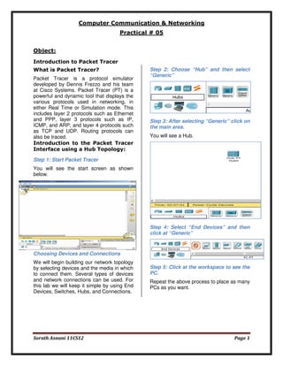
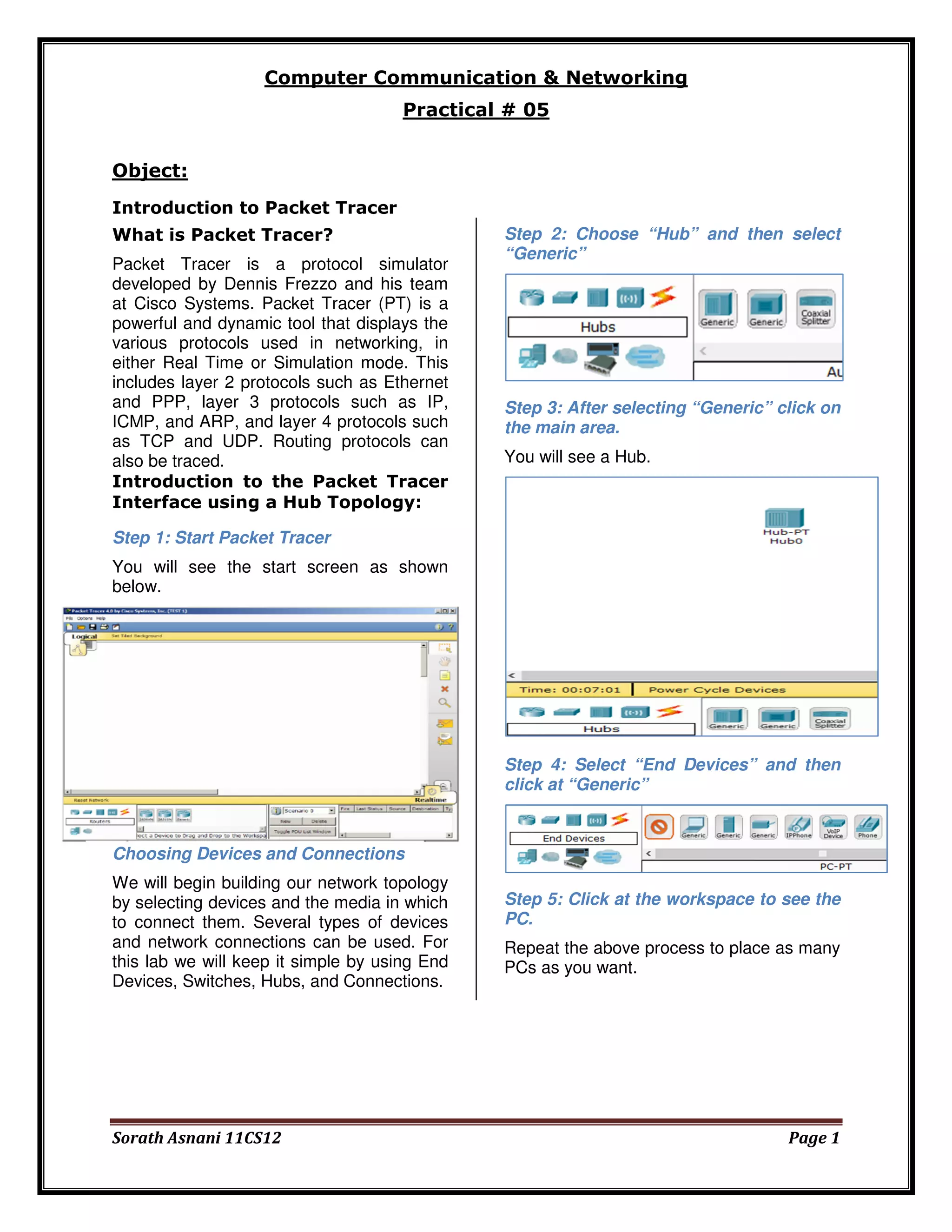
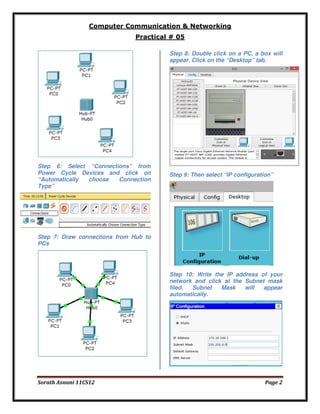
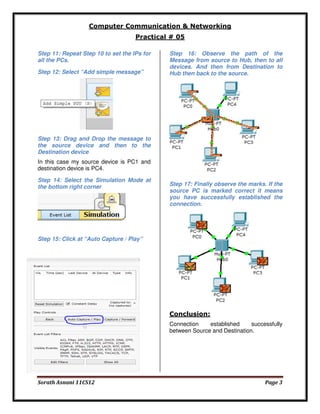

The document provides an introduction to Packet Tracer, a protocol simulator by Cisco that illustrates various networking protocols in real-time or simulation mode. It outlines a practical exercise involving the building of a network topology using devices and connections, specifically focusing on a hub-based configuration. The conclusion confirms the successful establishment of a connection between source and destination devices.