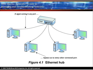
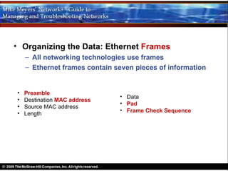
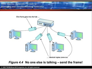
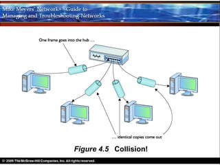
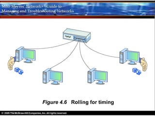
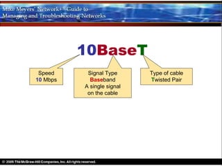
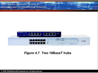
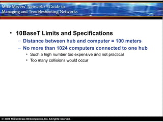
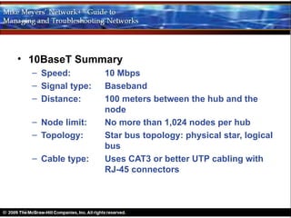
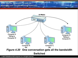
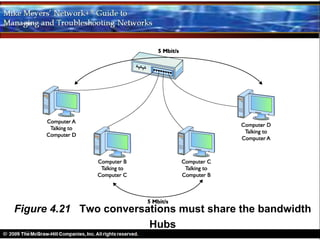
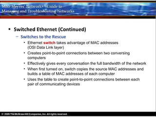
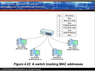
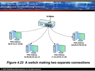
6. β’ First Ethernet implementation
β Develop by Xerox in 1973
β Based on bus topology
β Transferred data at 3Mbps max
β Evolved into todayβs Ethernet standards
Ethernet is a standard for a family of network
technologies that share the same basic bus topology,
frame type, and network access method.
7. β’ Next iteration of Ethernet
β DIX standard (ca 1979)
β DIX = Digital Equipment (DEC)+Intel+Xerox
β Transferred data at 10Mbps max
8. β’ Standardization
β DIX transferred control to IEEE
β IEEE created the 802.3 (Ethernet) subcommittee
β’ 10BaseT
β Earliest version of Ethernet to use UTP cabling
β Used data frames and CSMA/CD
9. β’ Topology
β Hybrid star-bus
β Hub at center
β’ Electronic repeater
β’ Each connection on hub is a port
β’ Each Ethernet NIC on network is a node.
β’ Does not send signal back down the originating port
11. β’ Organizing the Data: Ethernet Frames
β All networking technologies use frames
β Ethernet frames contain seven pieces of information
β’ Preamble
β’ Data
β’ Destination MAC address
β’ Pad
β’ Source MAC address
β’ Frame Check Sequence
β’ Length
14. β’ Ethernet Security Vulnerability
β Sniffers can order a NIC to run in promiscuous mode
β In promiscuous mode, the NIC processes all frames
β There are programs, such as AntiSniff, which network
administrators can use to detect sniffers on an
Ethernet network.
15. CSMA/CD
Carrier Sense Multiple Access Collision Detection
Each NIC on the network All machines have If two NICs transmit at
examines the wire before equal access to the the same time, a colli-
sending a frame. If the wire. Access to the sion results. NICs may
node detects traffic, it will wire is on a first- listen to detect a
back off a random amount come, first-served collision.
of time and try again. basis
16. Figure 4.4 No one else is talking β send the frame!
20. β’ 10BaseT
β Created in 1990
β Over 99% of all networks use this or its newer versions
β Two or more computers connected to a central hub
β NICs connect with wires per 802.3 standards
β Hubs for 10BaseT
β’ Vary in size, shape, and number of ports
β’ Need electrical power
21. 10BaseT
Speed Signal Type Type of cable
10 Mbps Baseband Twisted Pair
A single signal
on the cable
23. β’ 10BaseT (Continued)
β UTP
β’ Uses CAT3 or better with RJ-45 connectors
β’ Two pairs of wires required (four-pair cable commonly used)
β’ One pair of wires sends data to the hub
β’ The other pair receives data from the hub
β RJ-45 connector
β’ Introduced with 10BaseT
β’ Each pin connects to a single wire in cable
β’ Devices put voltage on the individual wires
β’ Pins numbered from 1 to 8
24. Figure 4.8 A typical four-pair CAT 5e
unshielded twisted-pair cable
26. β’ RJ-45 Pin Assignments
β 1 and 2 send data
β 3 and 6 receive data
β’ RJ-45 Connector called a crimp
β Crimping is the act of installing an RJ-45 connector
β Crimper is the tool used
27. Figure 4.10 The pins on an RJ-45 connector are
numbered 1 through 8.
31. β’ 10BaseT Limits and Specifications
β Distance between hub and computer = 100 meters
β No more than 1024 computers connected to one hub
β’ Such a high number too expensive and not practical
β’ Too many collisions would occur
32. β’ 10BaseT Summary
β Speed: 10 Mbps
β Signal type: Baseband
β Distance: 100 meters between the hub and the
node
β Node limit: No more than 1,024 nodes per hub
β Topology: Star bus topology: physical star, logical
bus
β Cable type: Uses CAT3 or better UTP cabling with
RJ-45 connectors
33. β’ 10BaseFL
β Distance: two kilometers (2,000 meters) between the
hub and the node
β Immune to EMI β ideal for high-interference
environments
β More secure because difficult to tap into
β Multimode fiber-optic cables with ST or SC connectors
35. β’ 10BaseFL Summary
β Speed: 10Mbps
β Signal type: Baseband
β Distance: 2000 meters between hub and node
β Node limit: No more than 1,024 nodes per hub
β Topology: Star bus topology: physical star, logical
bus
β Cable type: Uses multimode fiber-optic cabling with
ST or SC connectors
36. β’ Connecting different types of Ethernet networks
β Same Ethernet packets, although different cabling and
hubs
β Media converter will connect differently-cabled
Ethernet networks
37. Figure 4.14 Typical copper-to-fiber Ethernet media
converter (photo courtesy of TRENDnet)
39. β’ Connecting Ethernet Segments
β Uplink Ports
β’ Connect two hubs using a straight-through cable
β’ Marked on hub
β’ One end of cable to the uplink in one hub, other end in regular port of
second hub
β’ Daisy chain no more than four hubs
β’ Uplink port may have a button to switch between regular or uplink
mode, electronically reversing the wires inside the hub for that port
β’ When connecting hubs
β Only daisy-chain hubs
β Take time to figure out the uplink ports
β If incorrectly connected, they simply will not work
44. β’ Connecting Ethernet Segments (Continued)
β Crossover Cables
β’ Another way to connect two hubs without an uplink port
β’ Connect via two normal ports using one crossover cable
β’ Crossover cable reverses the sending and receiving pairs on one
end
β’ One end crimped per TIA/EIA 568A
β’ Second end crimped per TIA/EIA 568B
45. Figure 4.19 A crossover cable reverses the
sending and receiving pairs
46. β’ Switched Ethernet
β The Trouble with Hubs
β’ A hub sends all packets out all ports
β’ Increased traffic will slow network
β’ Total bandwidth is 10 Mbps
β’ When two nodes attempt to use wire at the same time, CSMA
reduces the effective speed to ~ 5 Mbps
β’ Add more conversations: network slows further
47. Figure 4.20 One conversation gets all the bandwidth
Switched
49. β’ Switched Ethernet (Continued)
β Switches to the Rescue
β’ Ethernet switch takes advantage of MAC addresses
(OSI Data Link layer)
β’ Creates point-to-point connections between two conversing
computers
β’ Effectively gives every conversation the full bandwidth of the network
β’ When first turned on, switch copies the source MAC addresses and
builds a table of MAC addresses of each computer
β’ Uses the table to create point-to-point connections between each
pair of communicating devices
51. Figure 4.23 A switch making two separate connections
52. β’ Switched Ethernet (Continued)
β Switches to the Rescue (Continued)
β’ Switch makes CSMA/CD insignificant
β’ Connect switches any way you wish
β’ Commonly connected in a tree organization
β’ No collisions
Note: The Historical/Conceptual information on page 59 is not part of the exam, but it will give the students a good background understanding of how Ethernet has evolved. Point this out, and inform them that they will see more changes in Ethernet as technology advances.
Tech Tip (top of Page 59) IEEE The source for all things Ethernet is but a short click away on the Internet. For starters, check www.ieee802.org . Note on Page 59: There have been many versions of Ethernet over the years. The earliest versions, named 10Base5 and 10Base2, are long obsolete. As of 2009, CompTIA finally dropped these ancient technologies from the CompTIA Network+ exam. Rest in peace, 10Base5 and 10Base2!
Tech Tip (bottom of Page 59) Defining Ethernet Providing a clear and concise definition of Ethernet provides one of the major challenges in teaching networking. The difficulty comes because nobody else has a good definition and Ethernet has changed over the years to incorporate new and improved technology. Hereβs a stab at a current definition. Ethernet is a standard for a family of network technologies that share the same basic bus topology, frame type, and network access method. Because the technologies share these essential components, you can communicate between them just fine. The implementation of the network might be different, but the frames remain the same.
Note: The evolved Ethernet standards are the dominant network standards.
Teaching Tip Briefly ask the students to recall the size and makeup of a MAC address from Chapter 2. They should remember that a MAC address is a 48-bit (6-byte) binary hard-coded address that uniquely identifies each node on a network. It is usually shown in hexadecimal notation, the first six digits are the organizationally unique identifier (OUI), and the last six digits are the device ID.
Tip on Page 60: The terms frame and packet are often used interchangeably, especially on exams! This book uses the terms more strictly. Youβll recall from Chapter 2, βBuilding a Network with OSI,β that frames area based on MAC addresses; packets are generally associated with data assembled by the IP protocol at Layer 3 [Network layer] of the OSI seven-layer model.
Tip on Page 61: The CompTIA Network+ exam might describe MAC addresses as 48-bit binary addresses or 6-byte binary addresses. Teaching Tip Cross Check Take time to have the students review what they learned in Chapter 2 about MAC addresses by having them answer the questions in the Cross Check on Page 61: Where does the NIC gets its MAC address? How does the MAC address manifest on the card? At what layer or layers of the OSI seven-layer model does the NIC operate?
Note: A node is any NIC connected to an Ethernet network. Note on the bottom of Page 61: There are many situations where one computer might have two or more NICs, so one physical system might have more than one node! Note: There are programs, such as AntiSniff, which network administrators can use to detect sniffers on an Ethernet network.
Tip on Page 63: CSMA/CD is a network access method that maps to the IEEE 802.3 standard for Ethernet networks. Note on Page 63: In an Ethernet network, a collision domain is a group of nodes that hear each otherβs traffic. A segment is certainly a collision domain, but there are ways to connect segments together to create larger collision domains. If the collision domain gets too large, youβll start running into traffic problems that manifest as general network sluggishness. Thatβs one of the reasons to break up networks into smaller groupings.
Tip on Page 65: If you ever run into a situation on a 10BaseT or later network in which none of the computers can get on the network, always first check the hub!
Note on Page 65: The names of two earlier true bus versions of Ethernet, 10Base5 and 10Base2, gave the maximum length of the bus. 10Base5 networks could be up to 500 meters long, for example, whereas 10Base2 could be almost 200 meters (though in practice topped out at 185 meters).
Teaching Tip Cross Check Spend a few minutes having the students answer the
Teaching Tip Cross Check Take time to have the students review what they learned about CAT levels in Chapter 3 by having them answer the questions in the Cross Check on Page 66: Could 10BaseT use Cat2? Could it use CAT6? What types of devices can use CAT1?
Note on Page 66: The real name for RJ-45 is β8 Position 8 Contact (8P8C) modular plug.β The name RJ-45 is so dominant, however, that nobody but the nerdiest of nerds call it by its real name. Stick to RJ-45.
Teaching Tip Although it is stated in the text, be sure to emphasize that in spite of having separate wires for sending and receiving, 10BaseT does not allow for simultaneous send-receive. Rules of CSMA/CD apply. Later versions of Ethernet changed this rule.
Tech Tip (Page 67): 568A and 568B An easy trick to remembering the difference between 568A and 568B is the word βGO.β The green and orange pairs are swapped between 568A and 568B, whereas the blue and brown pairs stay in the same place! Tip on Page 67: For the CompTIA Network+ exam, you wonβt be tested on the TIA/EIA 568A or B color codes. Just know that they are industry-standard color codes for UTP cabling. Note on bottom of Page 67: 10BaseFL is often just called 10BaseF.
Note: It might be a good idea to go ahead and discuss the wiring patterns for the patch, crossover, and straight through CAT5 cables. It would help even more if you could not only show the students how to make a cable, but also allow them to make one. Letting them actually make the cables does more for their understanding. Lab Project 4.2 in the Instructor Manual lists some websites with great instructions β including at least one good video at www.viewdo.com.
Note: There are many situations where one computer might have two or more NICs, so one system might have more than one node!
Teaching Tip 1000 meters = approximately 6/10 of a mile It might be a good idea to go ahead and discuss the wiring patterns for the patch, crossover, and rollover CAT5 cables. It would help even more if you could not only show the students how to make a cable, but also allow them to make one. Letting them actually make the cables does more for their understanding.
Teaching Tip Higher-end hubs do not come with uplink ports. Therefore, crossover cables are the only option for connecting these hubs.
Teaching Tip It is easy for students to miss that fact that hubs cannot be arranged in a star. That is, multiple hubs cannot be connected to a central hub.
It might be a good idea to go ahead and discuss the wiring patterns for the patch, crossover, and rollover CAT5 cables. It would help even more if you could not only show the students how to make a cable, but also allow them to make one. Letting them actually make cables does more for their understanding.
Tech Tip (Page 71) Crossing Crossovers If you mess up your crossover connections, you wonβt cause any damage, but the connection will not work. Think about it. If you take a straight cable (that is, not a crossover cable) and try to connect two PCs directly, it wonβt work. Both PCs will try to use the same send and receive wires. When you plug the two PCs into a hub, the hub electronically crosses the data wires, so one NIC sends and the other can receive. If you plug a second hub to the first hub using regular ports, you essentially cross the cross and crate a straight connection again between the two PCs! That wonβt work. Luckily, nothing gets hurt (except your reputation if one of your colleagues notes your mistake!).
Tip on Page 72: The classic difference between a hub and a switch is in the repeating of packets during normal use . Although itβs true that switches initially forward all frames, in regular use they filter by MAC address. Hubs never learn and always forward all frames.
Note on Page 73: Because a switch filters traffic on MAC addresses (and MAC addresses run at Layer 2 of the OSI seven-layer model), switches are often called Layer 2 switches .