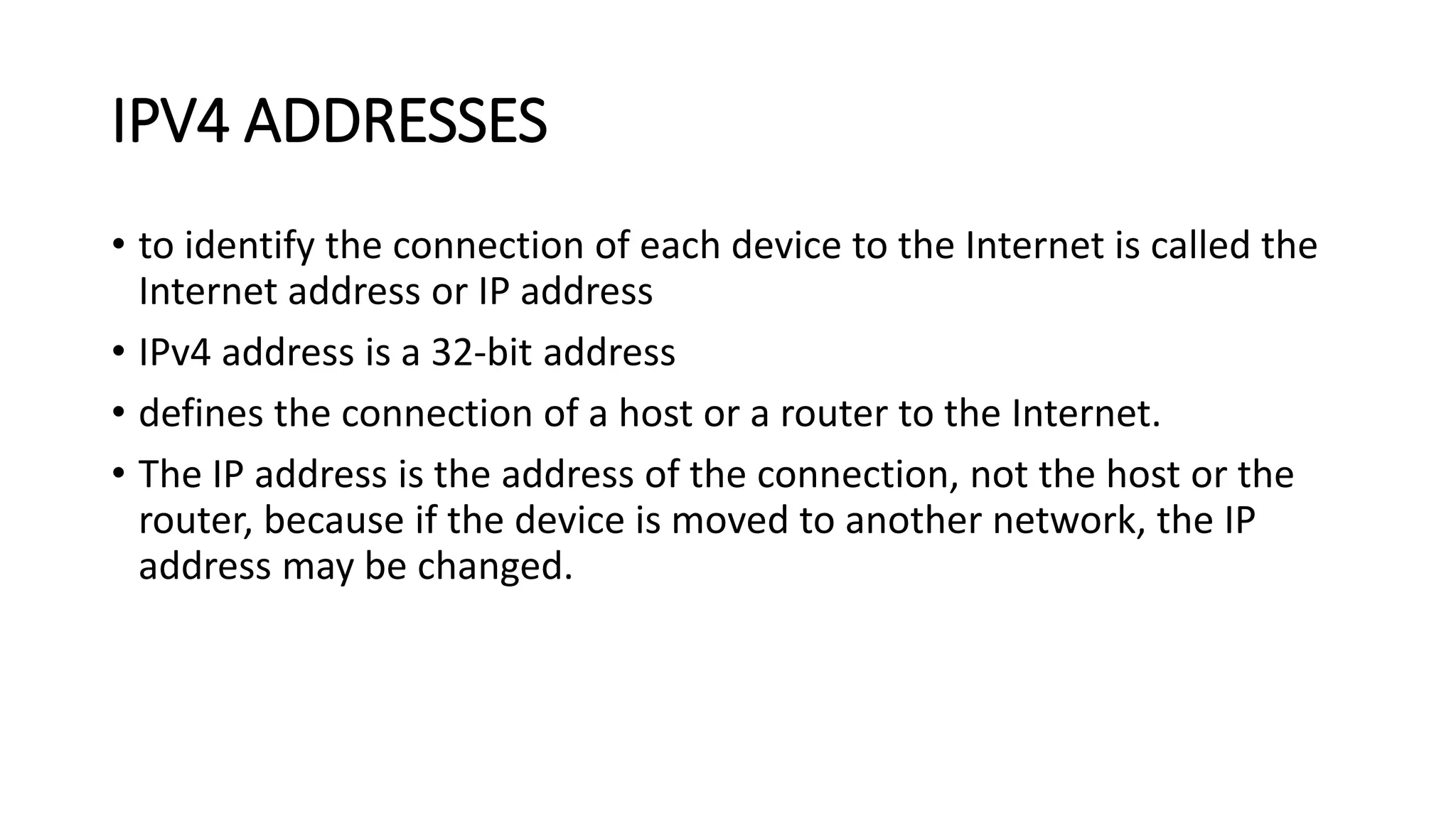
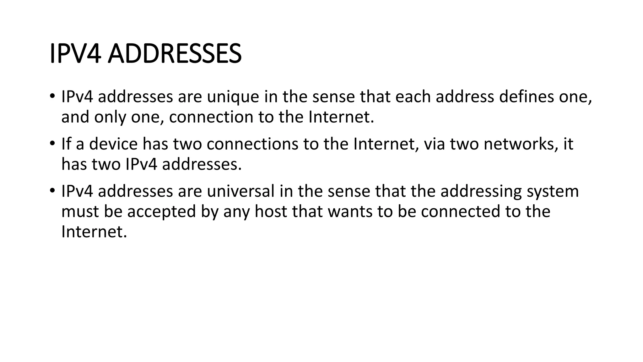
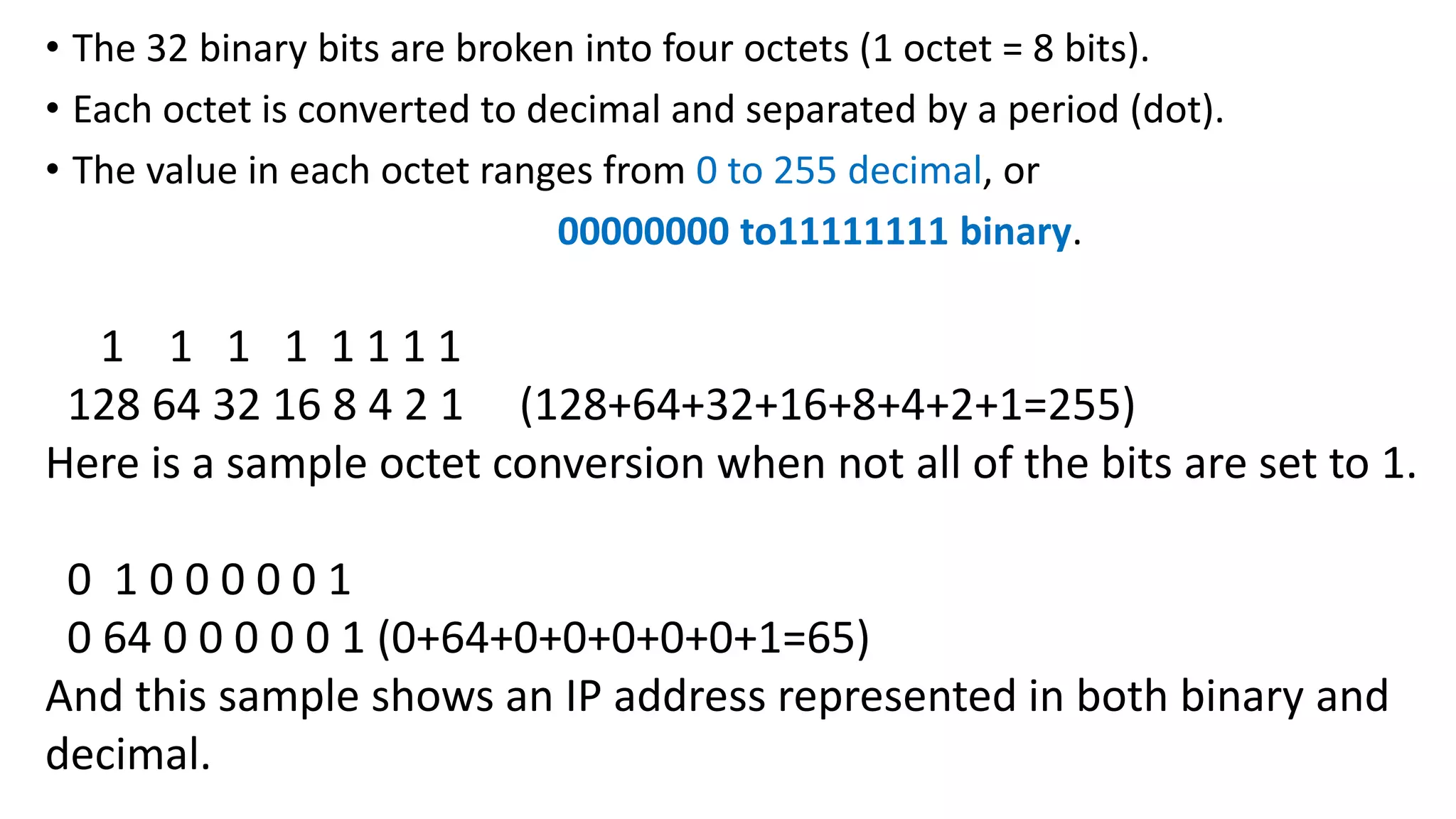
- IPv4 addresses are 32-bit addresses that uniquely identify devices connected to the Internet. They allow for over 4 billion unique addresses.
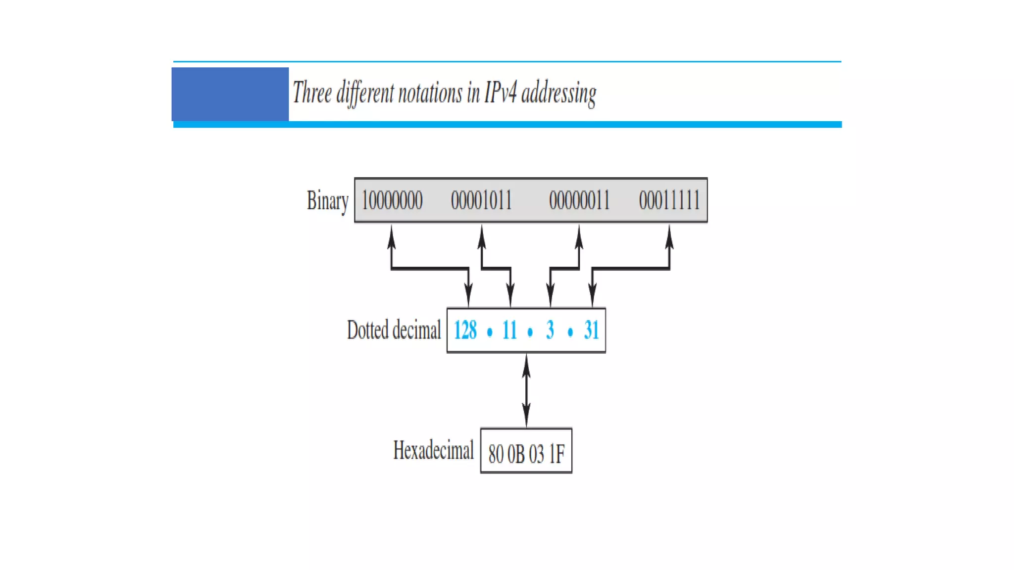
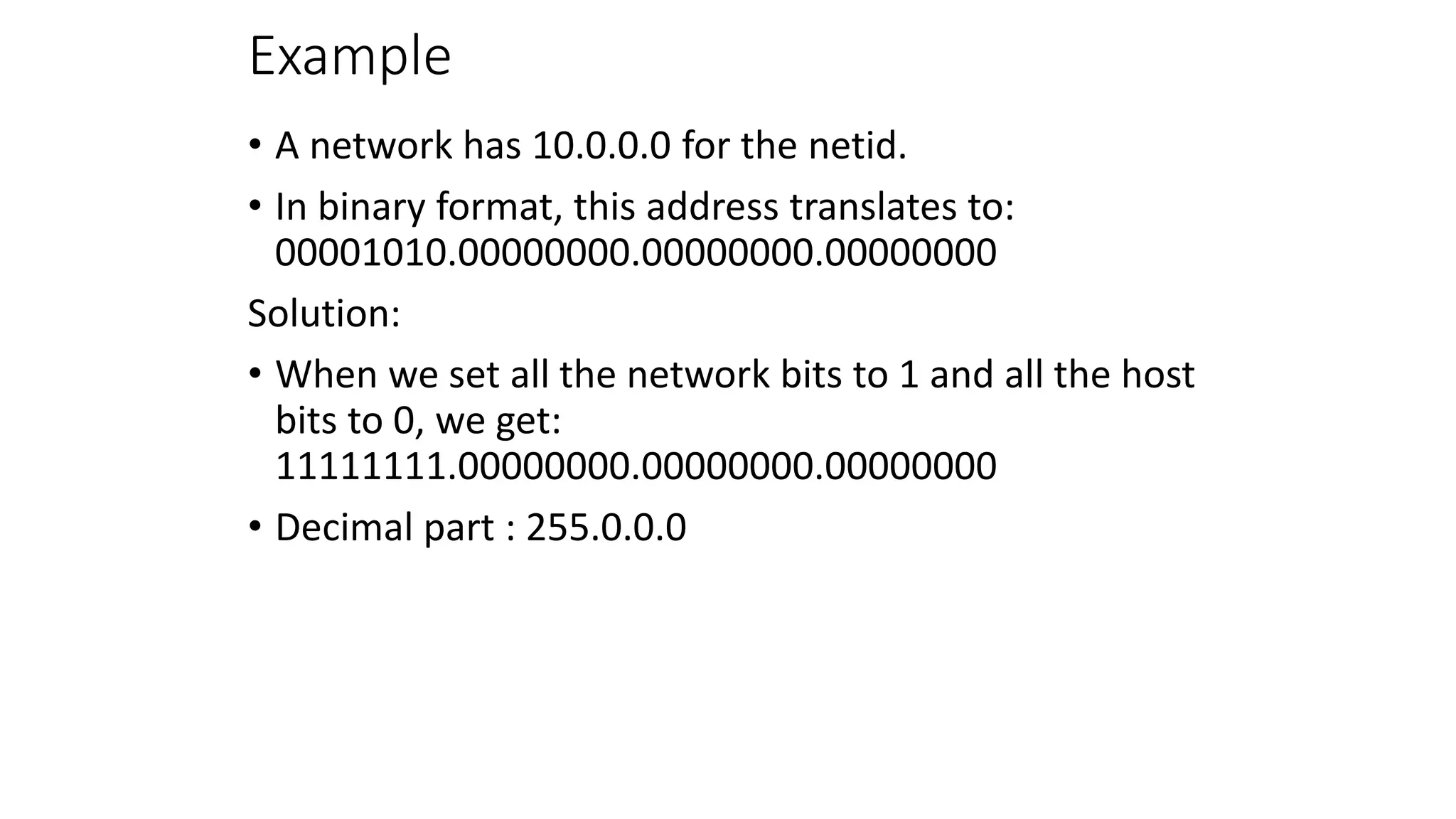
- IPv4 addresses can be written in binary, decimal dotted notation, or hexadecimal formats. They are hierarchical, with a network portion and host portion.
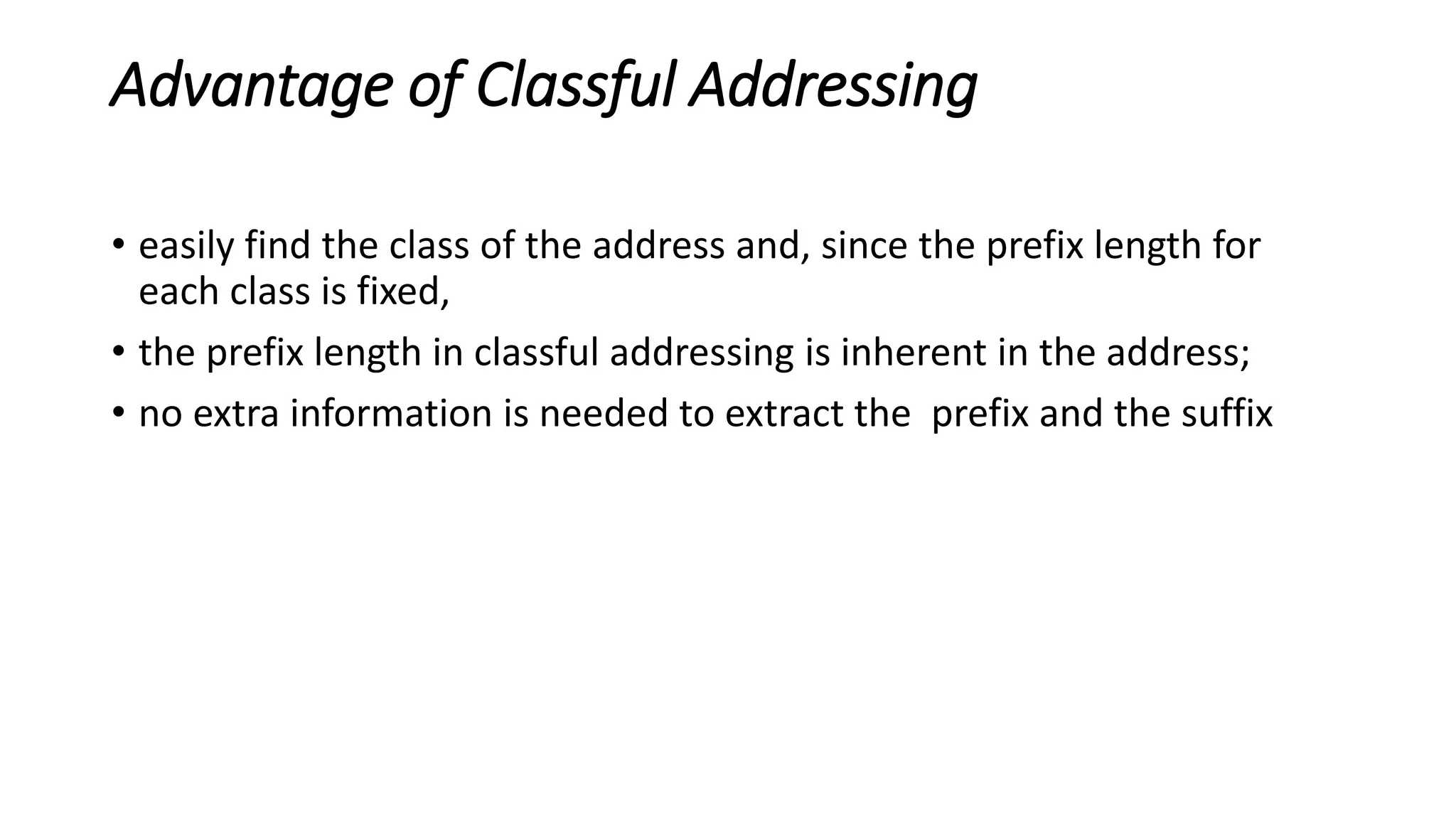
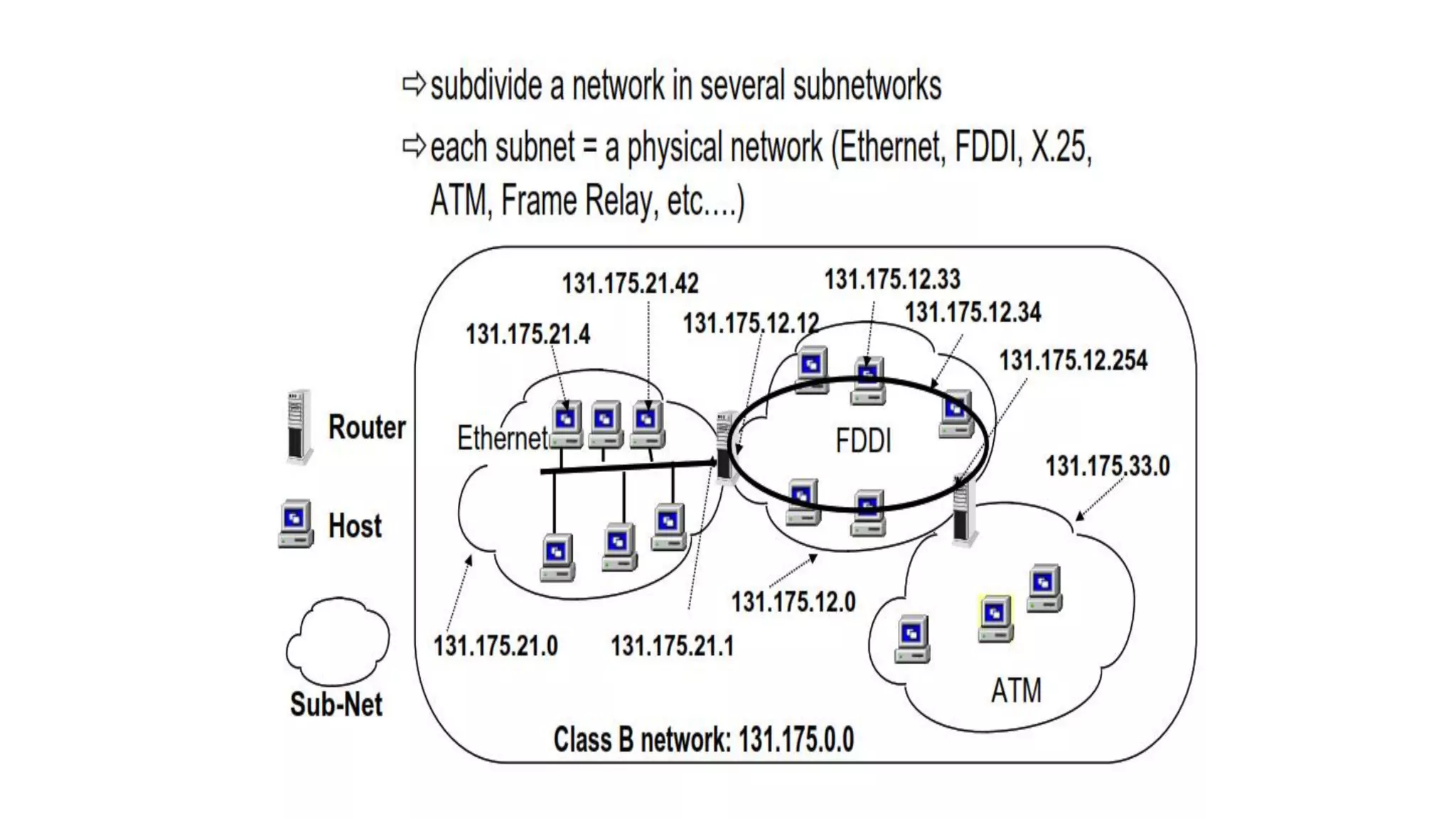
- Originally, IPv4 used classful addressing with fixed length prefixes to divide the address space. This led to inefficient address allocation and depletion.
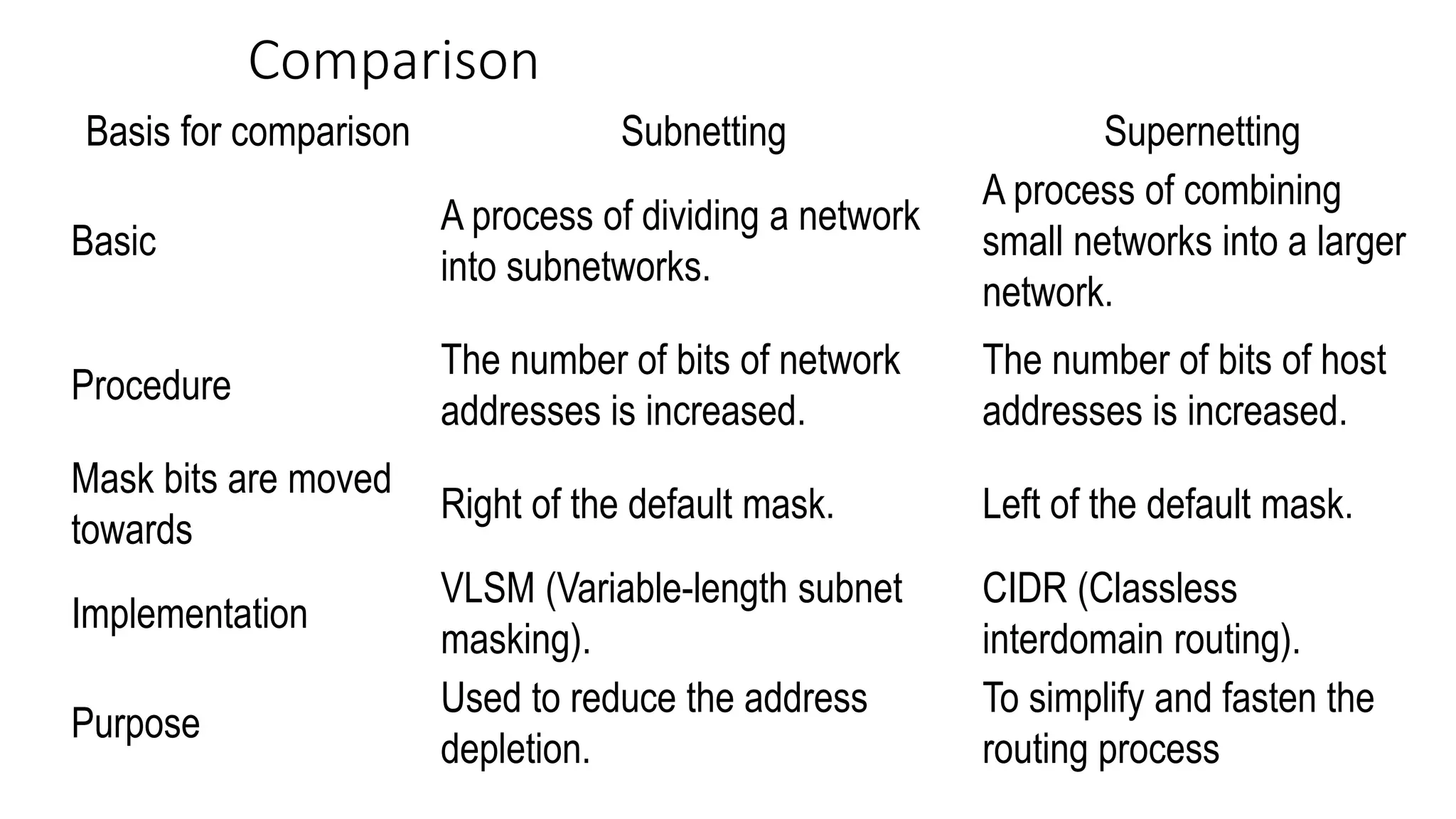
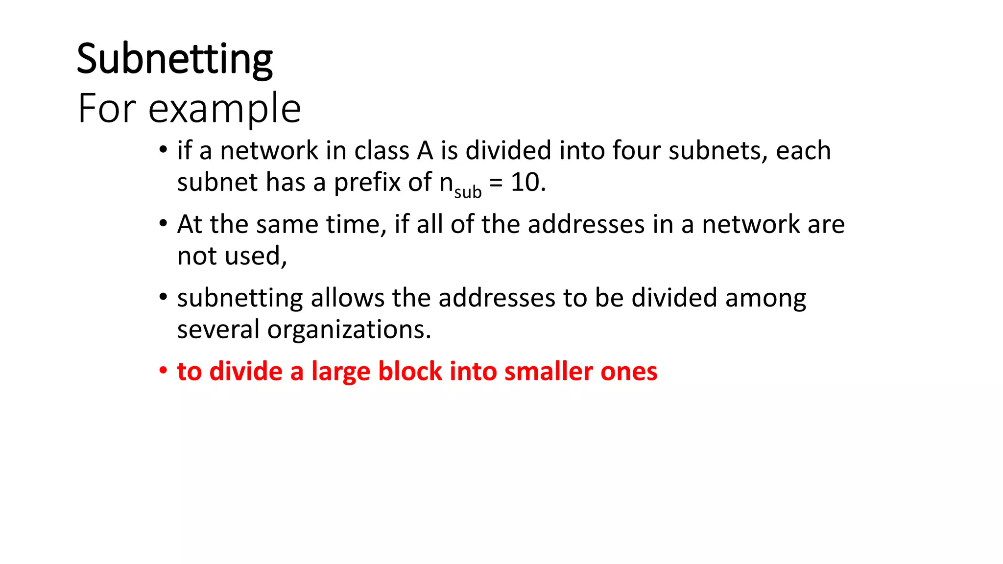
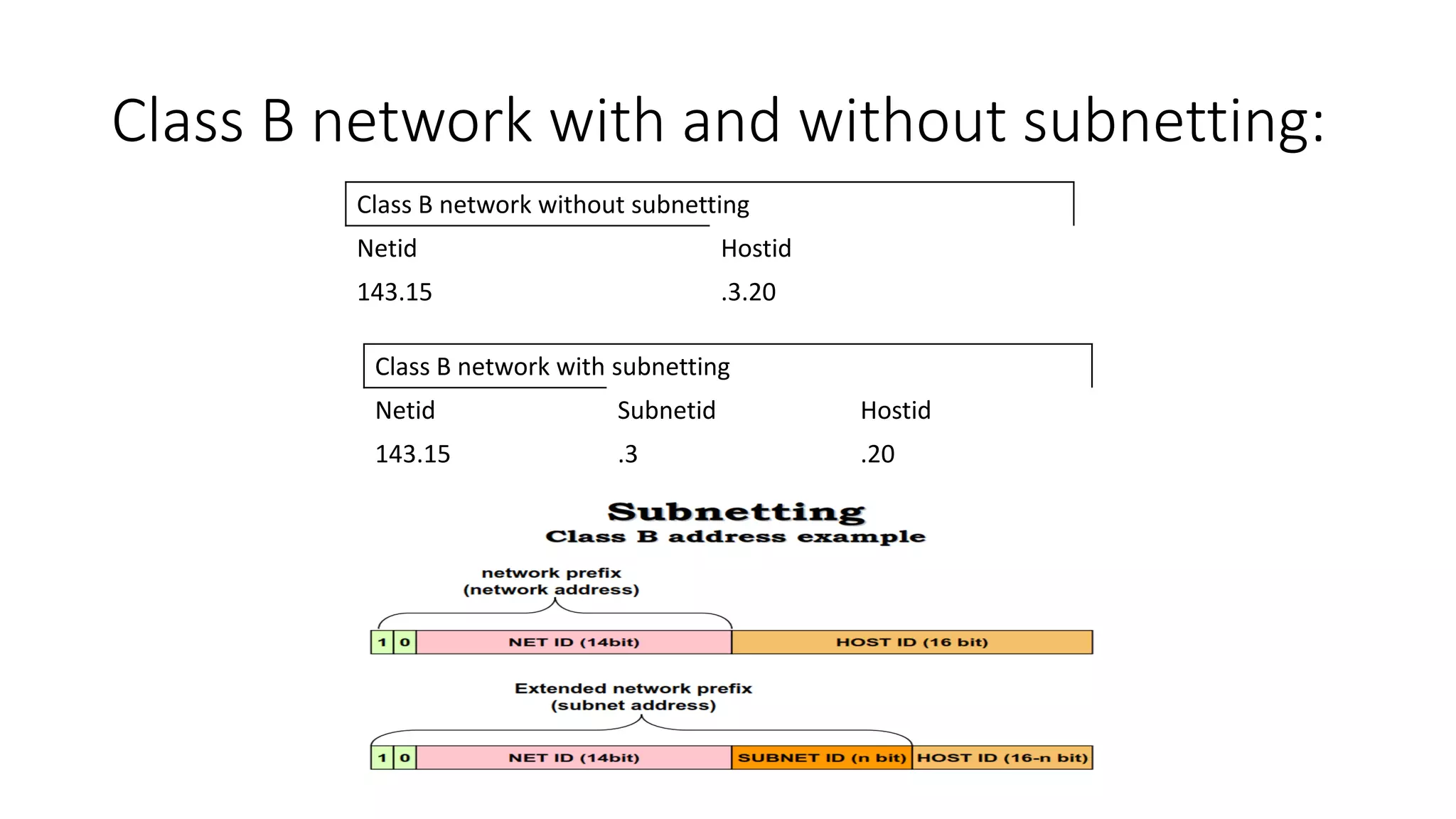
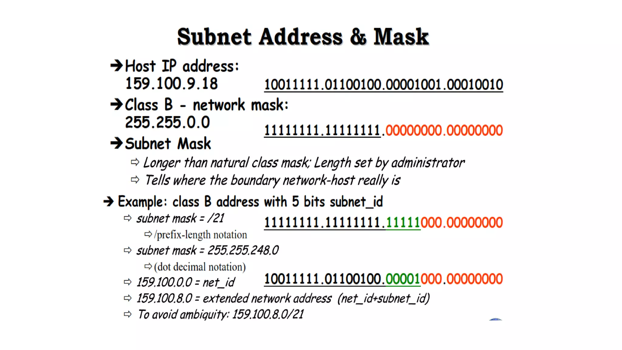
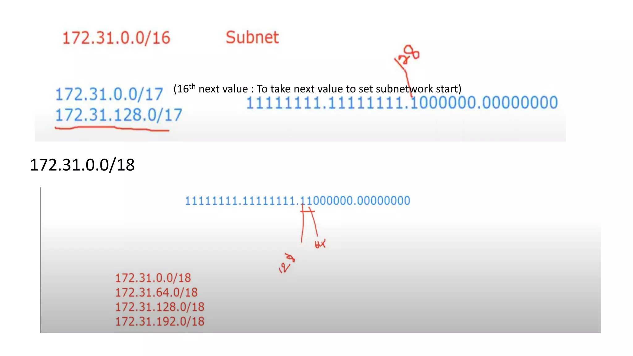
- Subnetting and supernetting were introduced to allow flexible division of networks into subnets and combining of networks. This helped optimize address usage.


![For 1st Subnet-
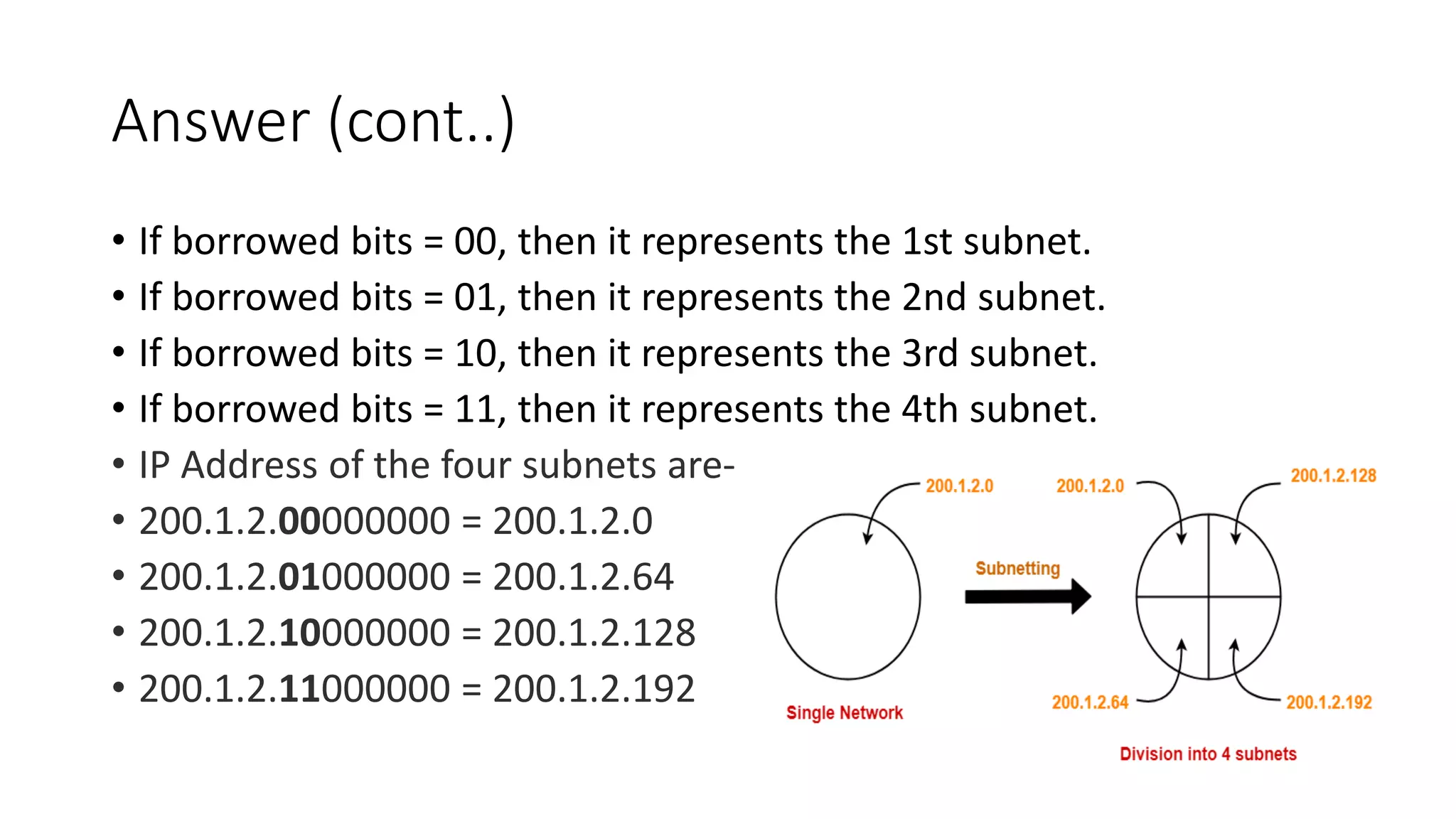
• IP Address of the subnet = 200.1.2.0
• Total number of IP Addresses = 27 = 128
• Total number of hosts that can be configured = 128 – 2(Reserved bits/special
address) = 126
• Range of IP Addresses =
[200.1.2.00000000, 200.1.2.01111111] = [200.1.2.0, 200.1.2.127]
• Direct Broadcast Address = 200.1.2.01111111 = 200.1.2.127
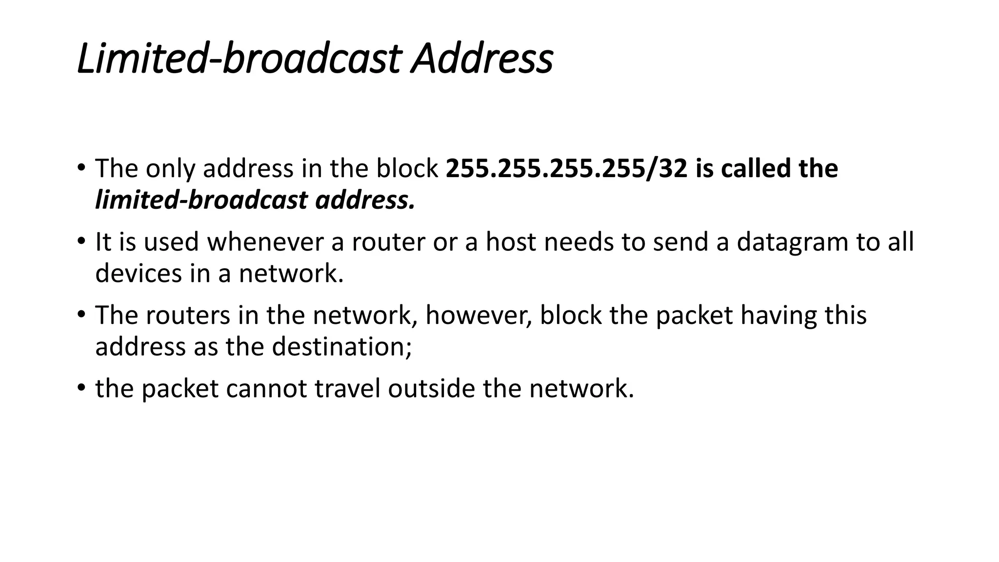
• Limited Broadcast Address = 255.255.255.255](https://image.slidesharecdn.com/ipv4addresses-211006101616/75/IPV4-addresses-37-2048.jpg)
![For 2nd Subnet-
• IP Address of the subnet = 200.1.2.128
• Total number of IP Addresses = 27 = 128
• Total number of hosts that can be configured = 128 – 2 = 126
• Range of IP Addresses =
[200.1.2.10000000, 200.1.2.11111111] = [200.1.2.128, 200.1.2.255]
• Direct Broadcast Address = 200.1.2.11111111 = 200.1.2.255
• Limited Broadcast Address = 255.255.255.255](https://image.slidesharecdn.com/ipv4addresses-211006101616/75/IPV4-addresses-38-2048.jpg)


![For 1st Subnet-
• IP Address of the subnet = 200.1.2.0
• Total number of IP Addresses = 26 = 64
• Total number of hosts that can be configured = 64 – 2 = 62
• Range of IP Addresses = [200.1.2.00000000, 200.1.2.00111111] =
[200.1.2.0, 200.1.2.63]
• Direct Broadcast Address = 200.1.2.00111111 = 200.1.2.63
• Limited Broadcast Address = 255.255.255.255](https://image.slidesharecdn.com/ipv4addresses-211006101616/75/IPV4-addresses-42-2048.jpg)
![For 2nd Subnet-
• IP Address of the subnet = 200.1.2.64
• Total number of IP Addresses = 26 = 64
• Total number of hosts that can be configured = 64 – 2 = 62
• Range of IP Addresses = [200.1.2.01000000, 200.1.2.01111111] =
[200.1.2.64, 200.1.2.127]
• Direct Broadcast Address = 200.1.2.01111111 = 200.1.2.127
• Limited Broadcast Address = 255.255.255.255](https://image.slidesharecdn.com/ipv4addresses-211006101616/75/IPV4-addresses-43-2048.jpg)
![For 3rd Subnet-
• IP Address of the subnet = 200.1.2.128
• Total number of IP Addresses = 26 = 64
• Total number of hosts that can be configured = 64 – 2 = 62
• Range of IP Addresses = [200.1.2.10000000, 200.1.2.10111111] =
[200.1.2.128, 200.1.2.191]
• Direct Broadcast Address = 200.1.2.10111111 = 200.1.2.191
• Limited Broadcast Address = 255.255.255.255](https://image.slidesharecdn.com/ipv4addresses-211006101616/75/IPV4-addresses-44-2048.jpg)
![For 4th Subnet-
• IP Address of the subnet = 200.1.2.192
• Total number of IP Addresses = 26 = 64
• Total number of hosts that can be configured = 64 – 2 = 62
• Range of IP Addresses = [200.1.2.11000000, 200.1.2.11111111] =
[200.1.2.192, 200.1.2.255]
• Direct Broadcast Address = 200.1.2.11111111 = 200.1.2.255
• Limited Broadcast Address = 255.255.255.255](https://image.slidesharecdn.com/ipv4addresses-211006101616/75/IPV4-addresses-45-2048.jpg)


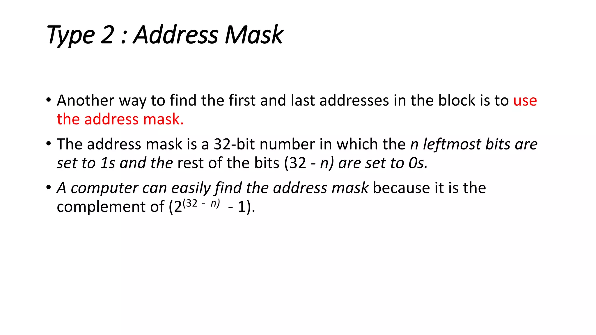
![Address Mask
• Another way to find the first and last addresses in the block is to use the
address mask.
• find the address mask because it is the complement of (232 − n − 1).
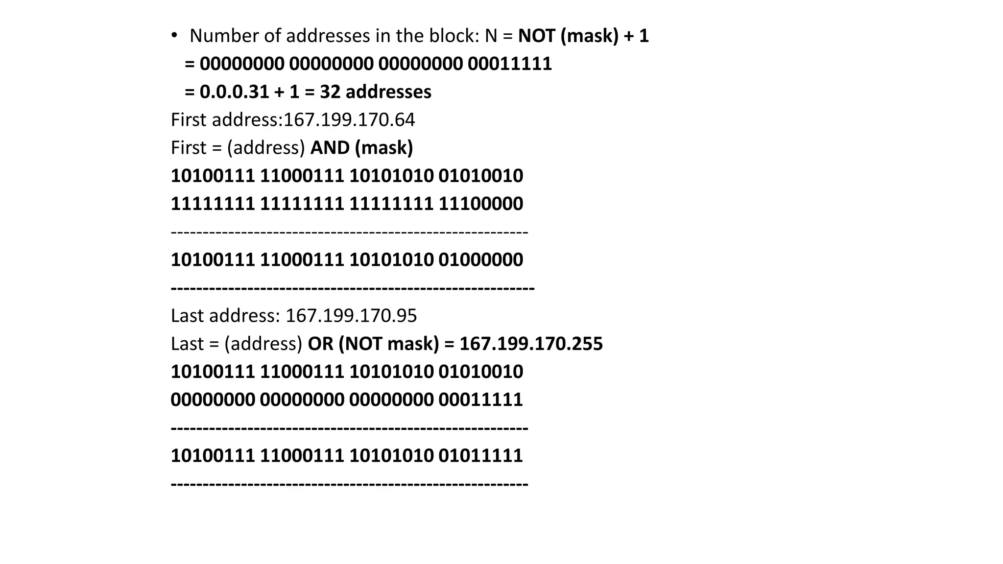
• 1. The number of addresses in the block N = NOT (mask) + 1.
• 2. The first address in the block = (Any address in the block) AND (mask).
• 3. The last address in the block = (Any address in the block) OR [(NOT (mask)].](https://image.slidesharecdn.com/ipv4addresses-211006101616/75/IPV4-addresses-90-2048.jpg)
![Address Mask
• The reason for defining a mask in this way is that it can be
used by a computer program to extract the information in
a block, using the three bit-wise operations NOT, AND,
and OR.
1. The number of addresses in the block N = NOT (mask) +
1.
2. The first address in the block = (Any address in the
block) AND (mask).
3. The last address in the block = (Any address in the
block) OR [(NOT (mask)].](https://image.slidesharecdn.com/ipv4addresses-211006101616/75/IPV4-addresses-92-2048.jpg)