Download as PDF, PPTX


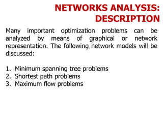


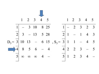
![FLOYD’S ALGORITHM
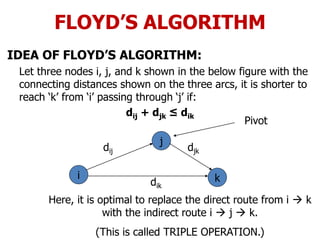
Use to find the shortest path between any two nodes
in the network.
• Floyd’s algorithm represents an ‘n’ node network as a
square matrix with ‘n’ rows and ‘n’ columns.
• Where:
Dn = [ dij ] and Sn = Matrix of the node –
Sequence
• For matrix Dn: Entry (i, j) of the matrix gives the
distance dij from node – ‘i’ to node – ‘j’, which is finite
if ‘i’ is linked directly to ‘j’, and infinite otherwise.](https://image.slidesharecdn.com/networkanalysis-161104024423/85/Network-analysis-26-320.jpg)
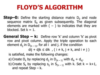


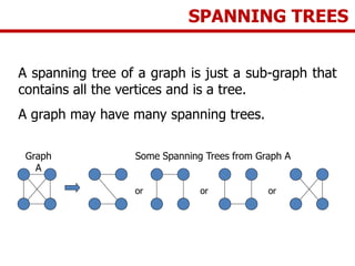
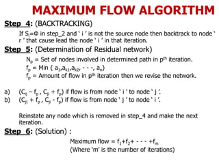
![MAXIMUM FLOW ALGORITHM
NOTATIONS:
Cij = Initial capacity of arc from node ‘ i ’ to node ‘ j ’.
Cji = Initial capacity of arc from node ‘ j ’ to node ‘ i ’.
Cij = Residual capacity of arc from node ‘ i ’ to node ‘ j ’.
Cji = Residual capacity of arc from node ‘ i ’ to node ‘ j ’.
[ aj , i ] = Denotes that aj amount of flow is received at node ‘
j’ from node ‘ i ’.](https://image.slidesharecdn.com/networkanalysis-161104024423/85/Network-analysis-41-320.jpg)
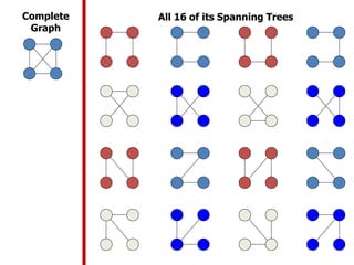
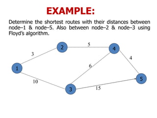
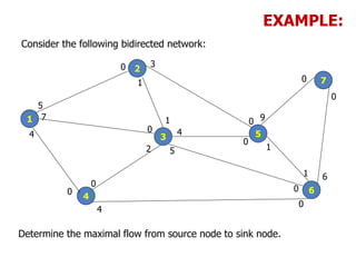
![MAXIMUM FLOW ALGORITHM
Step_1: Set a1= ∞, then label node_1 as [∞, -].
Step_2: Si=Set of unlabelled nodes ‘ j ’ directly connected to node
‘ i ’ , with positive capacity i.e.: Cij>0.
Step_3: Determine Cik = Max { Cij }
For Example:
j ε Si
1
3
2
4
[∞, -]
5
10
8
[10,1]
S1 = { 2,3,4}
Max = { C12,C13,C14}
= C13
Thus, ak = Cik, label node_k {ak,i}
Set i = k, go to step_2.](https://image.slidesharecdn.com/networkanalysis-161104024423/85/Network-analysis-42-320.jpg)
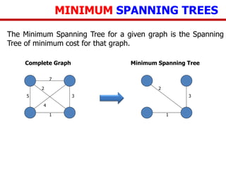
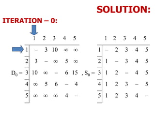
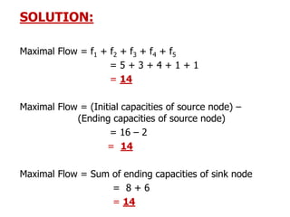
![SOLUTION:
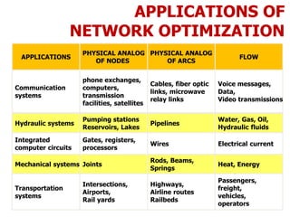
Iteration_1: -
1
2
3
4
5
6
7
7
50
0
6
0[∞ , -] [7 , 1]
[5 , 3]
[6 , 6]
f1 = 5
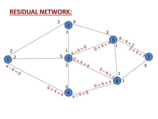
Now, We develop the Residual network from the
above network ---](https://image.slidesharecdn.com/networkanalysis-161104024423/85/Network-analysis-45-320.jpg)
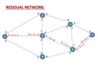
![SOLUTION:
Iteration_2: -
1
2
3
4
5
6
7
0
5
3 0 9
[∞ , -]
[5 , 1]
[9 , 5]
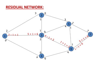
f2 = 3
Now again, We develop the Residual network from
the above network ---
[3 , 2]
0](https://image.slidesharecdn.com/networkanalysis-161104024423/85/Network-analysis-47-320.jpg)
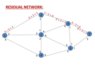
![Solution:
Iteration_3: -
1
2
3
4
5
6
7
0
4
3 0 6
[∞ , -]
[6 , 5]
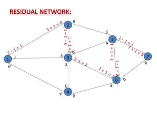
f3 = 4
Now again, We develop the Residual network from
the above network ---
[4 , 1]
3
4 0
5
[4 , 4]
0
4[5 , 6]
[4 , 3]](https://image.slidesharecdn.com/networkanalysis-161104024423/85/Network-analysis-49-320.jpg)
![Solution:
Iteration_4: -
1
2
3
4
5
6
7
2
4
1
[∞ , -]
[1 , 6]
f4 = 1
Now again, We develop the Residual network from
the above network ---
[4 , 6]
5
0 4
1
[4 , 3]
5
[2 , 1]](https://image.slidesharecdn.com/networkanalysis-161104024423/85/Network-analysis-51-320.jpg)
![Solution:
Iteration_5: -
1
2
3
4
5
6
7
2
3
1
[∞ , -]
[2 , 5]
f5 = 1
Now again, We develop the Residual network from
the above network ---
[4 , 6]
7
0 4
2
[3 , 3]
[2 , 1]
3
1
1
[1 , 2]
1
[1 , 6]
2](https://image.slidesharecdn.com/networkanalysis-161104024423/85/Network-analysis-53-320.jpg)
![Solution:
Iteration_6: -
1
2
3
4
5
6
7
1
2
[∞ , -]
[4 , 6]
0 4
3
[2 , 3]
6
[1 , 1]
Now, There is no way to move towards sink node. So,](https://image.slidesharecdn.com/networkanalysis-161104024423/85/Network-analysis-55-320.jpg)


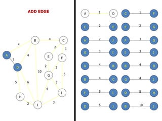
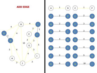
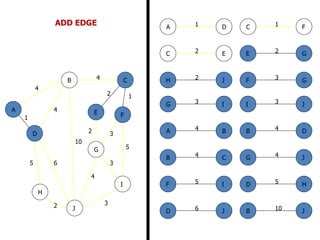
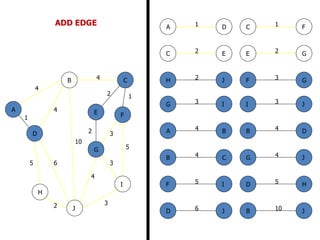
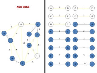
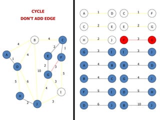
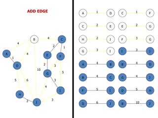
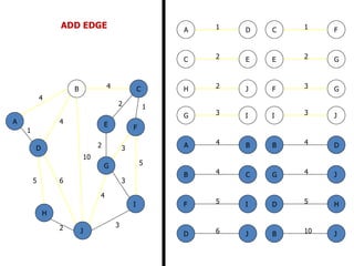
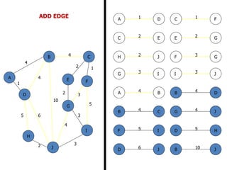
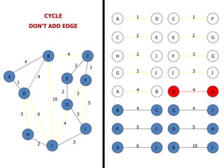
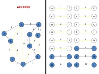
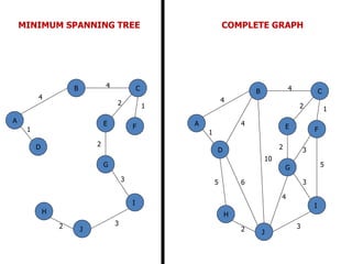
The document discusses network modeling and analysis, specifically covering minimum spanning tree problems, shortest path problems, and maximum flow problems. It provides examples of Kruskal's algorithm to find minimum spanning trees and Floyd's algorithm to find shortest paths between nodes in a network. The document contains examples applying these algorithms to sample network graphs.