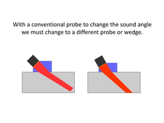
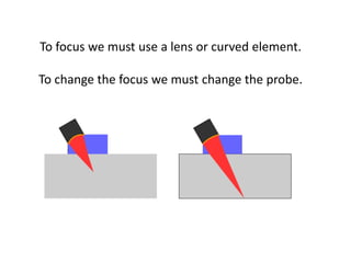
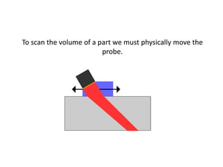
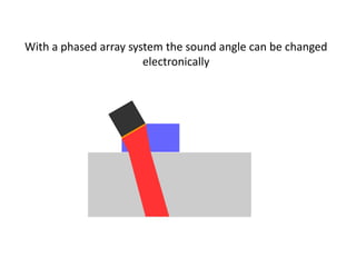
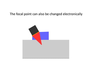
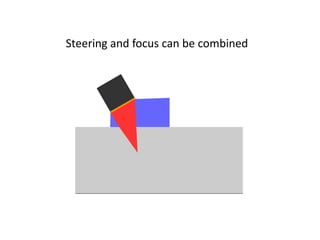
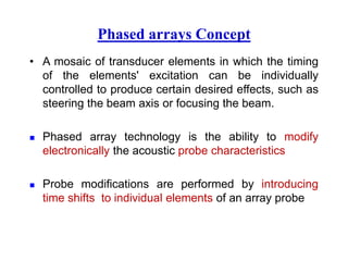
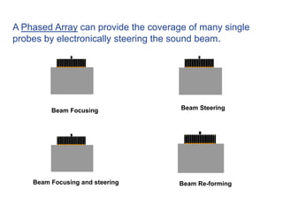
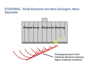
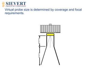
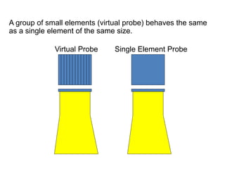
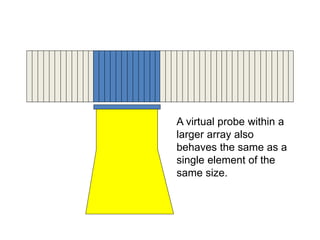
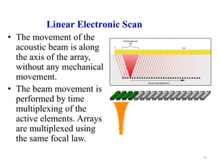
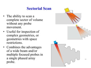
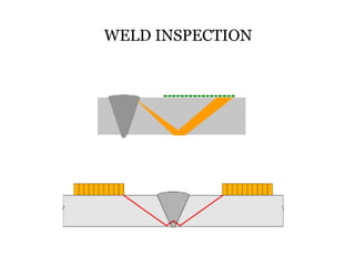
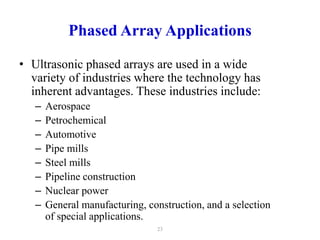
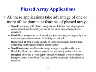
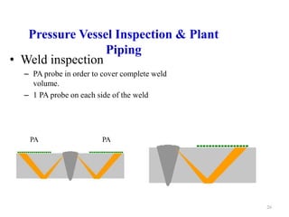
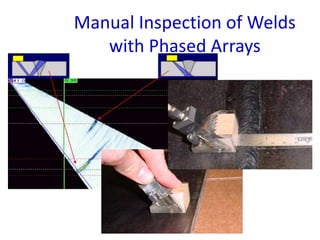
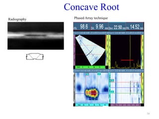
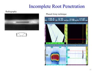
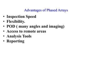
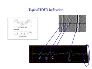
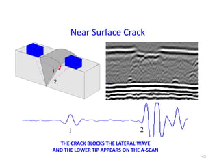
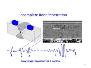
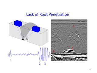
Phased Array & TOFD UT
With a conventional probe to change the sound angle
we must change to a different probe or wedge.
To focus we must use a lens or curved element.
To change the focus we must change the probe.
To scan the volume of a part we must physically move the
probe.
With a phased array system the sound angle can be changed
electronically
The focal point can also be changed electronically
Steering and focus can be combined
Phased arrays Concept
• A mosaic of transducer elements in which the timing
of the elements' excitation can be individually
controlled to produce certain desired effects, such as
steering the beam axis or focusing the beam.
 Phased array technology is the ability to modify
electronically the acoustic probe characteristics
 Probe modifications are performed by introducing
time shifts to individual elements of an array probe
Beam Focusing and steering
Beam Focusing Beam Steering
Beam Re-forming
A Phased Array can provide the coverage of many single
probes by electronically steering the sound beam.
Phased-Array Probe
Basically, a phased-array is a long conventional probe
cut into many elements.
Pitch:
– Center-to-center distance between two adjacent elements
Elevation:
– Width of a single element
Virtual Probe:
– The number of single elements pulsed as a group to
create the desired sound beam characteristics (aperture).
Phased Array Terminology
Pitch Elevation
Phased Array - Electronic Steering
Small overlap of adjacent
sound beams yields low
amplitude (weak) wavefront.
STEERING: Large Elements Are Less Divergent, Less
Steerable
Phased Array - Electronic Steering
Overlapping beams from
individual elements produces
higher amplitude wavefront.
STEERING: Small Elements Are More Divergent, More
Steerable
Nearfield
Farfield
Virtual probe size is determined by coverage and focal
requirements.
A group of small elements (virtual probe) behaves the same
as a single element of the same size.
Virtual Probe Single Element Probe
A virtual probe within a
larger array also
behaves the same as a
single element of the
same size.
One array probe does the job of many single-
element transducers:
Probe size
Probe focus
Probe scanning
Probe direction
Under Electronic
Control
Phased Array
Scanning Types
18
Linear Electronic Scan
• The movement of the
acoustic beam is along
the axis of the array,
without any mechanical
movement.
• The beam movement is
performed by time
multiplexing of the
active elements. Arrays
are multiplexed using
the same focal law.
19
Sectorial Scan
• The ability to scan a
complete sector of volume
without any probe
movement.
• Useful for inspection of
complex geometries, or
geometries with space
restrictions.
• Combines the advantages
of a wide beam and/or
multiple focused probes in
a single phased array
probe.
20
WELD INSPECTION
Phased Array
Applications
22
Phased Array Applications
• Ultrasonic phased arrays are used in a wide
variety of industries where the technology has
inherent advantages. These industries include:
– Aerospace
– Petrochemical
– Automotive
– Pipe mills
– Steel mills
– Pipeline construction
– Nuclear power
– General manufacturing, construction, and a selection
of special applications.
23
Phased Array Applications
• All these applications take advantage of one or
more of the dominant features of phased arrays:
– Speed: scanning with phased arrays is much faster than single-probe
conventional mechanical systems, at the same time offering better
coverage.
– Flexibility: setups can be changed in a few minutes, and typically a lot
more component-dimension flexibility is available.
– Inspection angles: a wide variety of inspection angles can be used,
depending on the requirements and the array.
– Small footprint: small matrix arrays can give significantly more
flexibility than conventional probes for inspecting restricted areas.
– Imaging: showing a “true depth” image of defects is much easier to
interpret than a waveform. The data can be saved and redisplayed as
required.
24
Industrial
Applications
25
Pressure Vessel Inspection & Plant
Piping
• Weld inspection
– PA probe in order to cover complete weld
volume.
– 1 PA probe on each side of the weld
26
PA PA
27
Manual Inspection of Welds
with Phased Arrays
40 degree beam 70 degree beam
27
Index axis
Scan axis
VC-END(D)
VIEW
Usound axis
Index axis
Side and End Views
Usound axis
VC-SIDE(B)
VIEW
Scan axis
28
Index axis
Scan axis
VC-TOP(C)
VIEW
Index axis
Scan axis
Top View
29
30
Root Crack
Radiography Phased Array technique
31
Porosity
Radiography Phased Array technique
32
Inclusion
Radiography Phased Array technique
33
Lack of Root Fusion
Radiography Phased Array technique
34
Concave Root
Radiography Phased Array technique
35
Incomplete Root Penetration
Radiography
Phased Array technique
Advantages of Phased Arrays
• Inspection Speed
• Flexibility.
• POD ( many angles and imaging)
• Access to remote areas
• Analysis Tools
• Reporting
36
Conditions and limitations of UT in Lieu of RT
• ASME CC2235 – Use of Ultrasonic
Examination in Lieu of Radiograph ( Boiler
and Pressure vessel )
• ASME CC181 – Use of Alternating
Ultrasonic Examination Acceptance criteria
( Pressure piping)
37
What is TOFD?
• Time-Of-Flight Diffraction (TOFD) relies on the
diffraction of ultrasonic energies from 'corners' and
'ends' of internal structures (primarily defects) in a
component being tested.
A-scan signals
Transmitter Receiver
Lateral wave
LW
Upper tip Lower tip
Back-wall reflection
BW
Data Visualization (TOFD)
Lateral
wave
Back-wall
A-scan
Indicatio
n
Visualization
White
+
Black
-
Amplitude
Time
Time
OneA-Scan is replaced by
one grey line
A-scan
41
Typical TOFD Indication
42
43
THE CRACK BLOCKS THE LATERAL WAVE
AND THE LOWER TIP APPEARS ON THE A-SCAN
2
1
1
2
Near Surface Crack
44
TWO SIGNALS FROM THE TOP & BOTTOM
1
2
3
4
1 2 3 4
Incomplete Root Penetration
45
Lack of Root Penetration
1
2
3
1
2
3
1
2 3
46
CLUSTER POROSITY
1
2
3
47
Lack of fusion -
interpass
1
2
3
48
Concave Root
TOFD technique
Radiography
49
Incomplete Root Penetration
TOFD technique
Radiography
Lack of Fusion, Side Wall
Note the two signals from the top & bottom
1
2
3
4
1
2
3
4
Porosity
Porosity may image in many forms
whether individual or cluster
1
2
3
1
2
Transverse Crack
In the LW we can observe the wide beam effect on the crack
1
2
3
4
1
2
3
1
2
3
Concave Root
• Distortion of back-wall echo
1
2
3
1
2
3
Advantages of TOFD
• Good midwall defect detection.
• Accurate sizing of defects using the time of arrivals
of diffracted signals.
• Defect detection even if defects are mis-oriented or
located away from the weld centreline.
• Excellent PoD for mid-wall defects
• Non-amplitude scanning and detection.
• Set-up independent of weld configuration.
• Dead zone at top surface (OD).
• Dead zone at bottom surface (ID).
Limitations of TOFD
55
Thanks for your
attention

Phased array & tofd