Download to read offline


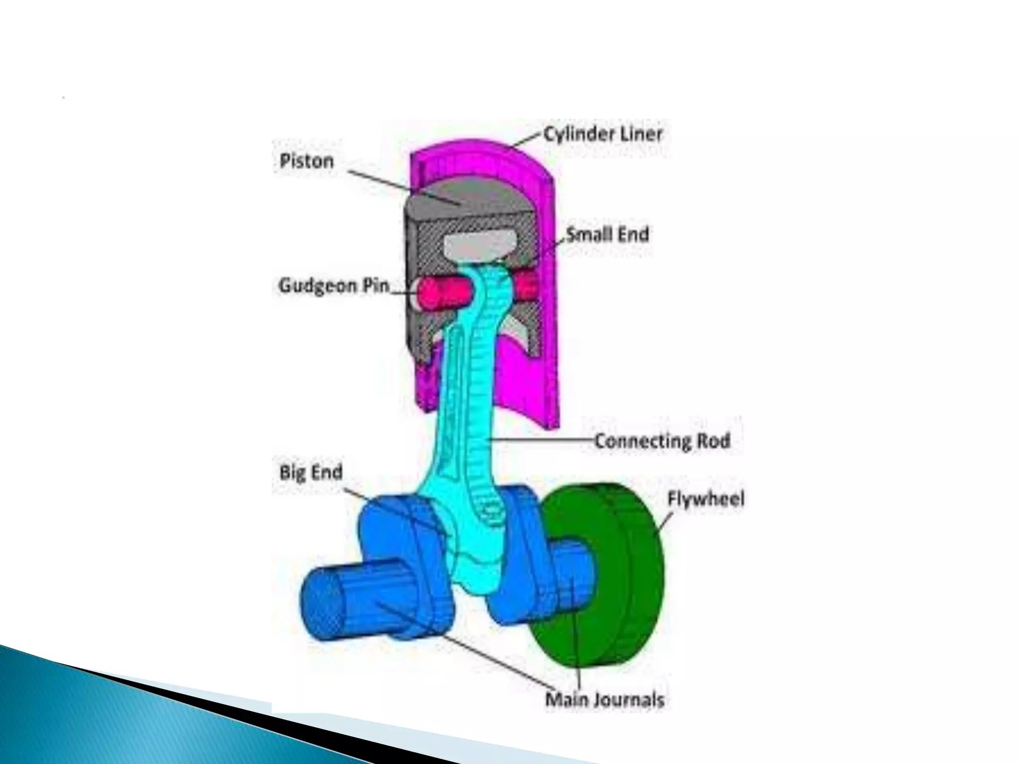
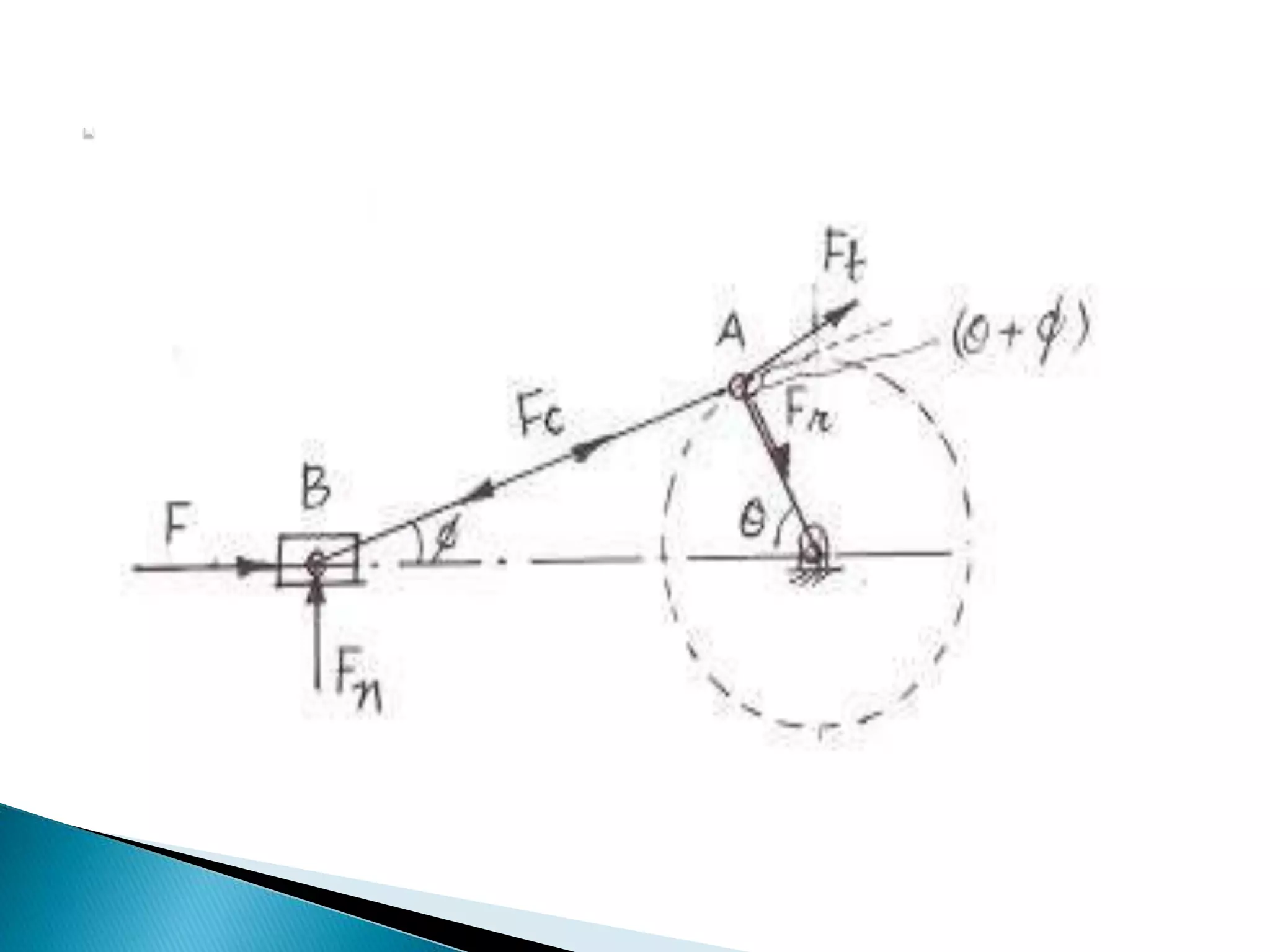
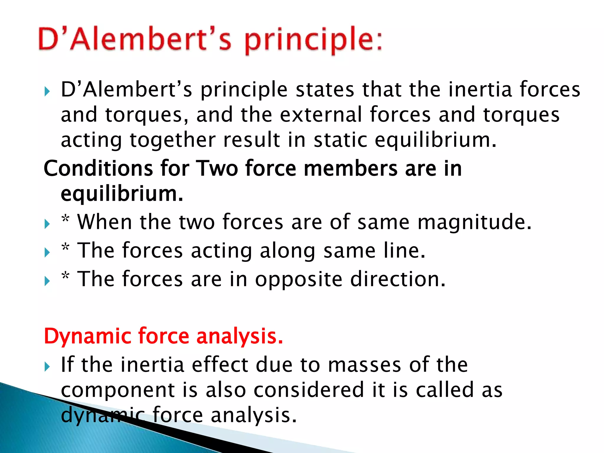
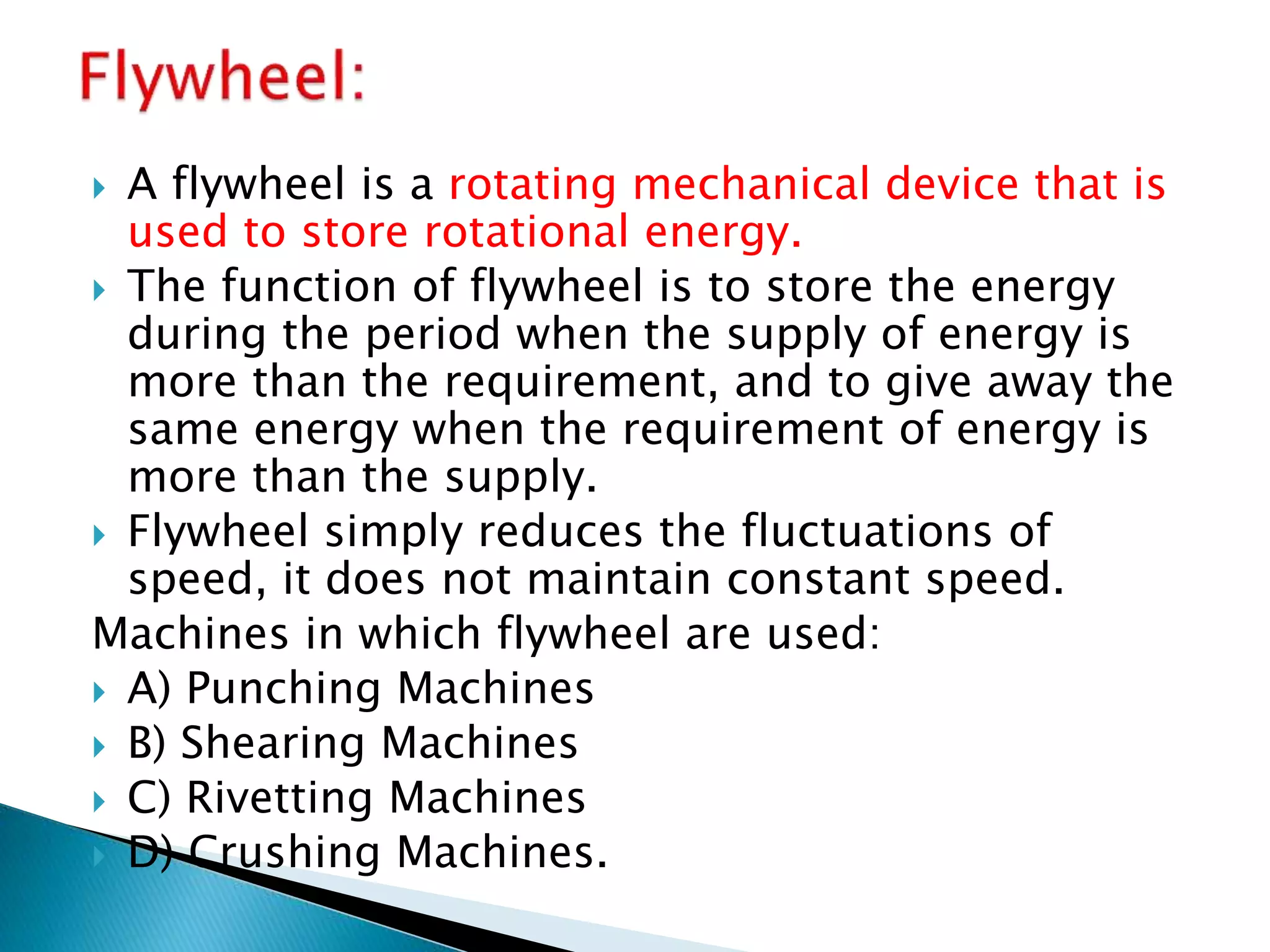
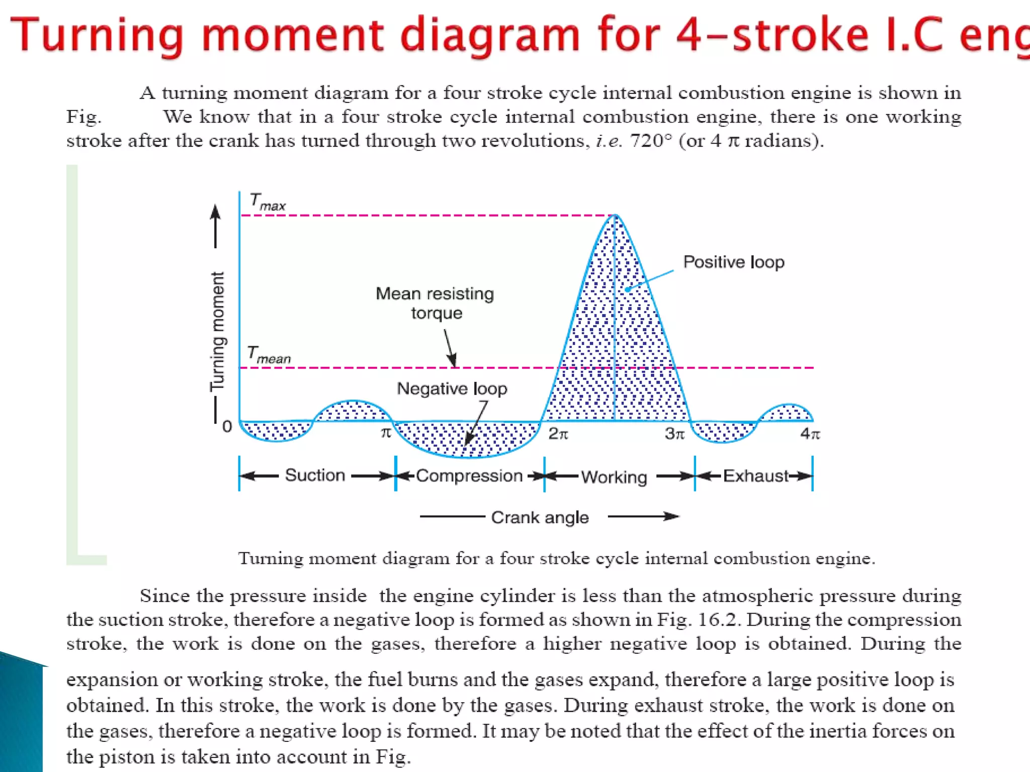
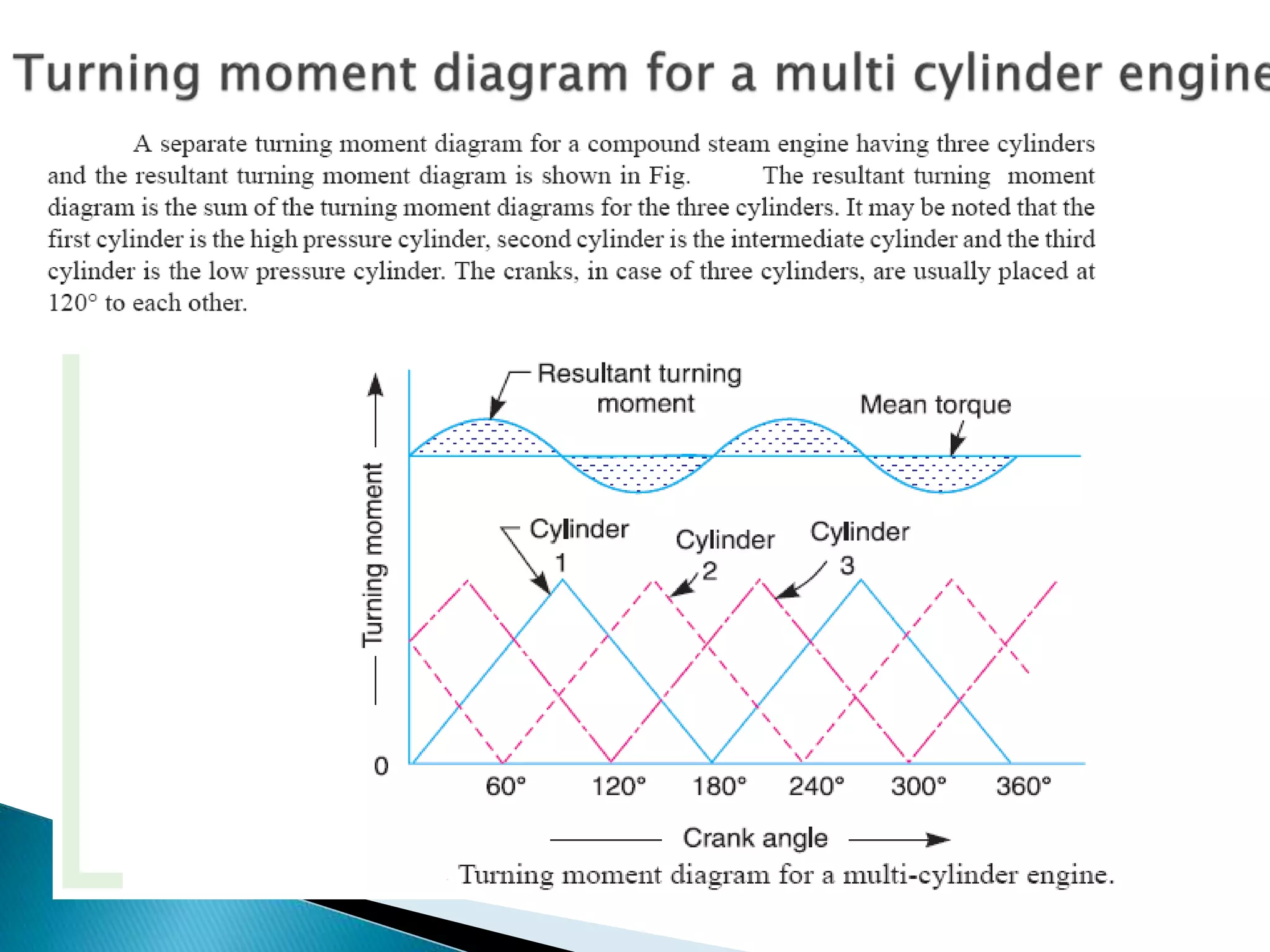
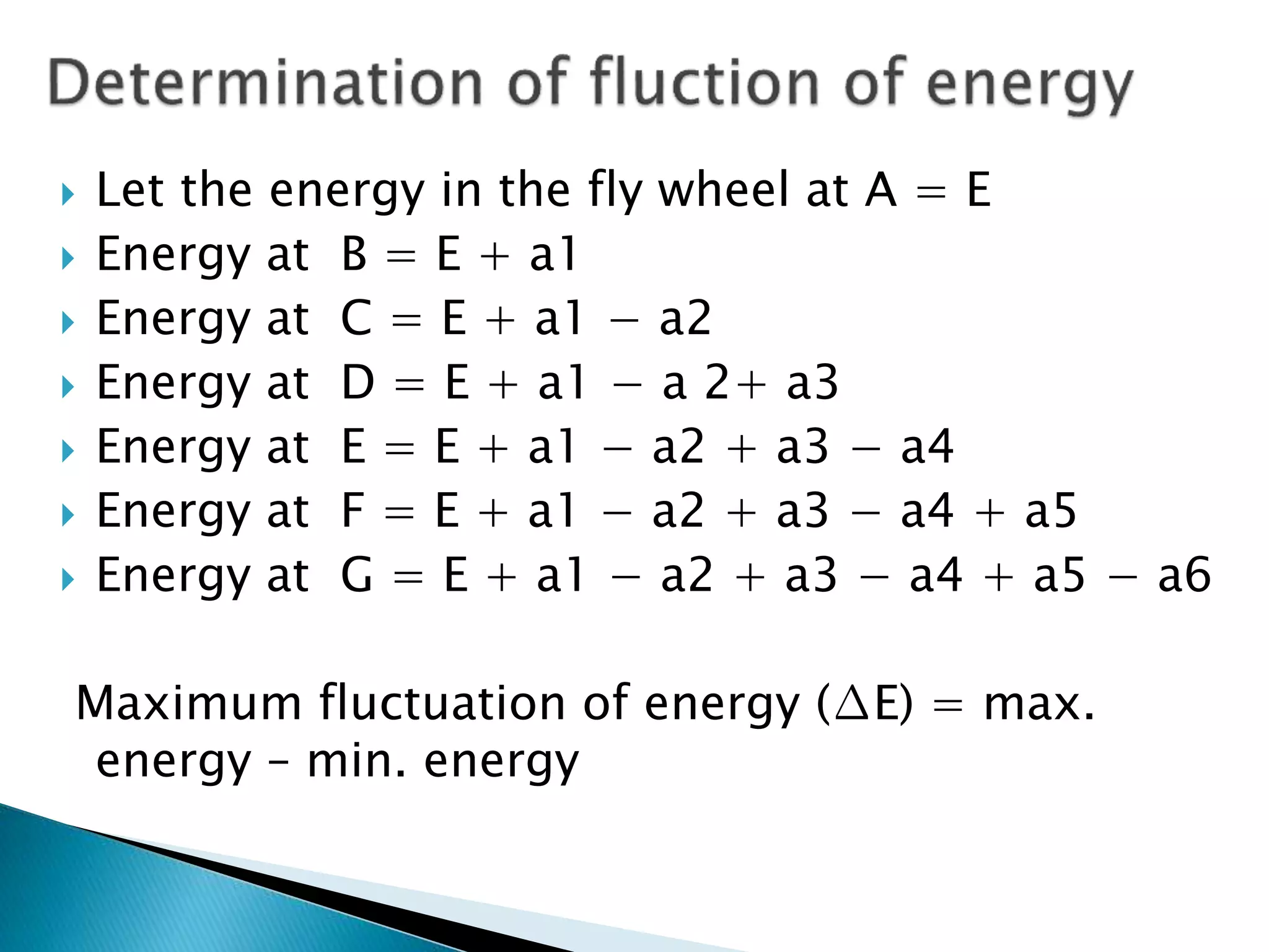
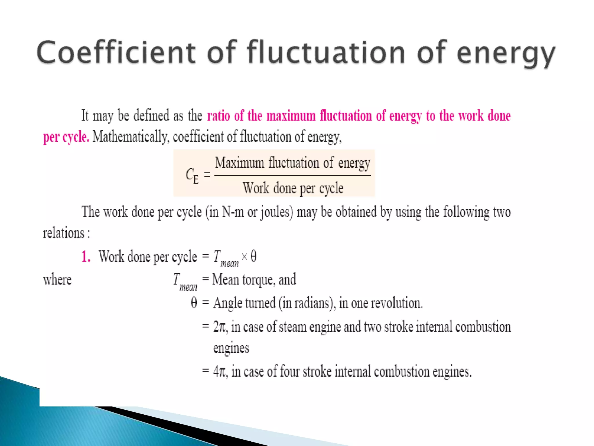
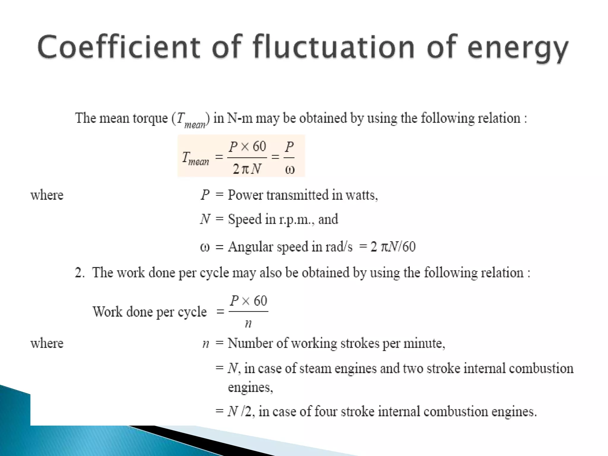
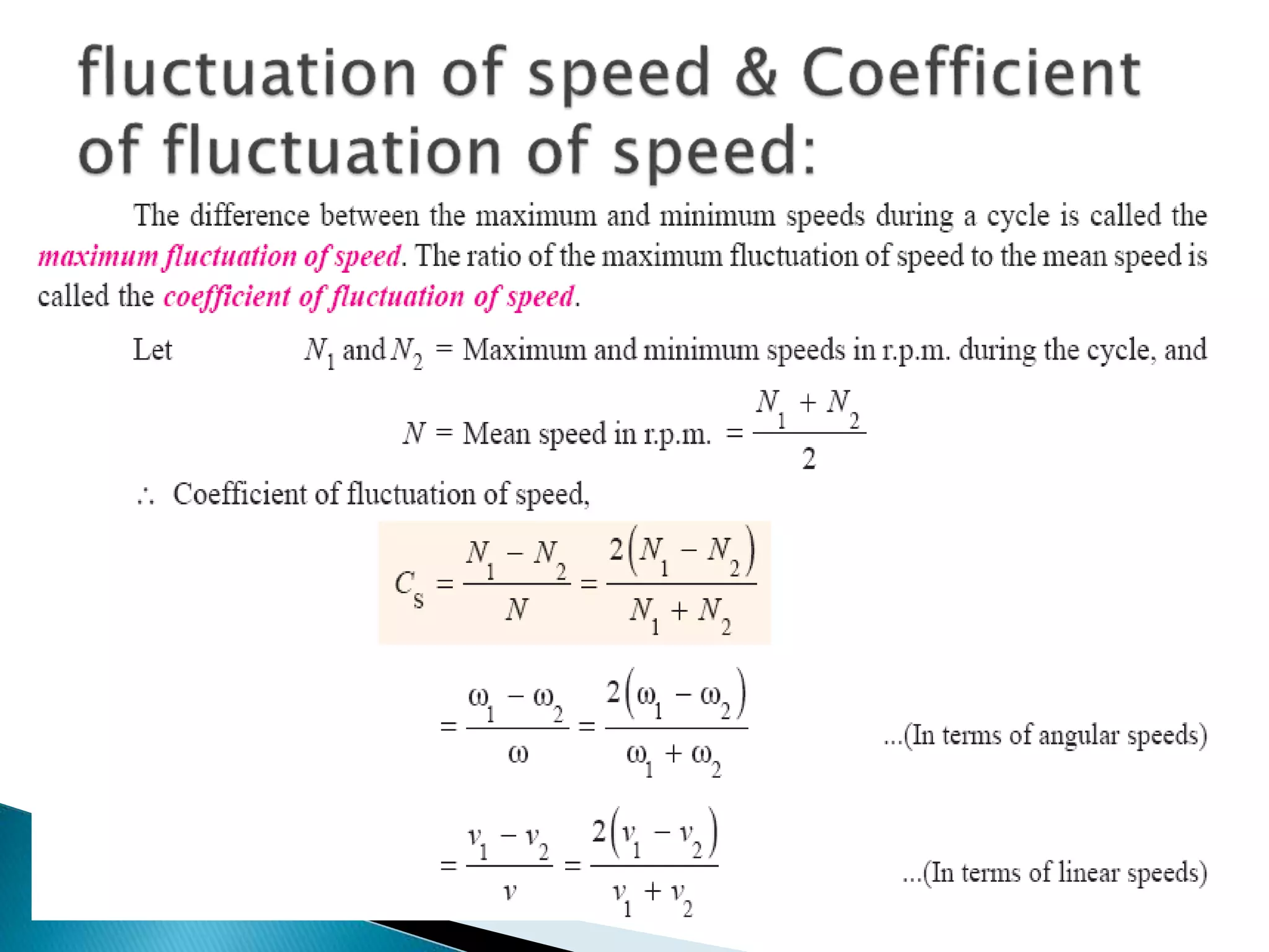

The document discusses force analysis and flywheels. It covers static and dynamic force analysis, including D'Alembert's principle. It also discusses applied forces, inertia, piston effort, crank effort, and crank-pin effort. Flywheels are described as rotating devices that store rotational energy to reduce fluctuations in speed. Turning moment diagrams are discussed as a way to analyze the torque on a crankshaft and determine work, power, mean torque, and maximum torque for engine design. Flywheel sizing is also informed by analyzing energy fluctuations using turning moment diagrams.