Downloaded 126 times
![FINAL TERM PRESENTATION
on
“MULTI-THRESHOLD”
SUB:- VLSI CIRCUIT DESIGN
SEC:-[E]](https://image.slidesharecdn.com/multi-threshold-151213152910/85/MULTI-Threshold-1-320.jpg)
![FINAL TERM PRESENTATION
on
“MULTI-THRESHOLD”
SUB:- VLSI CIRCUIT DESIGN
SEC:-[E]](https://image.slidesharecdn.com/multi-threshold-151213152910/75/MULTI-Threshold-1-2048.jpg)
![REFERENCES
[1] www.google.com/question _VLSI/
[2] www.geni.org/
[3] www.energypedia.info/
[4] www.eschooltoday.com/ MULTI THRESHOLD
.](https://image.slidesharecdn.com/multi-threshold-151213152910/85/MULTI-Threshold-10-320.jpg)


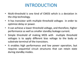
The document presents a final term presentation on 'multi-threshold' CMOS circuit design, highlighting its optimization of performance and power efficiency through the use of transistors with multiple threshold voltages. It discusses the unique methodology of the mtcmos technique, which reduces power dissipation using high threshold sleep transistors, while also outlining its applications in mobile technology and power gating. The presentation is prepared by a group of students for their EEE department faculty with references included for further reading.