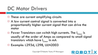
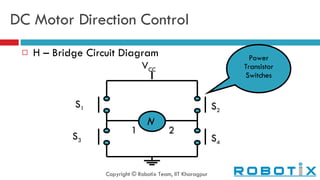
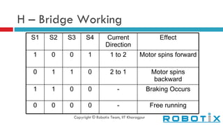
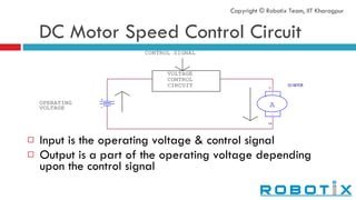
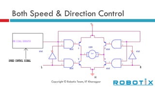
TECHNOLOGY ROBOTICS SOCIETY Indian Institute of Technology, Kharagpur
A TUTORIAL ON ROBOTICS Motor Drivers
DC Motor Drivers These are current amplifying circuits A low current control signal is converted into a proportionally higher current signal that can drive the motor Power Transistors can switch high currents. The I Cmax  is usually of the order of Amps as compared to small signal transistors which have I Cmax  in mA Example: L293d, L298, ULN2003 Copyright © Robotix Team, IIT Kharagpur
DC Motor Direction Control H – Bridge Circuit Diagram Copyright © Robotix Team, IIT Kharagpur S 1 S 3 S 2 S 4 M 1 2 V CC Power Transistor Switches
H – Bridge Working Copyright © Robotix Team, IIT Kharagpur S1 S2 S3 S4 Current Direction Effect 1 0 0 1 1 to 2 Motor spins forward 0 1 1 0 2 to 1 Motor spins backward 1 1 0 0 - Braking Occurs 0 0 0 0 - Free running
DC Motor Speed Control Circuit Input is the operating voltage & control signal Output is a part of the operating voltage depending upon the control signal Copyright © Robotix Team, IIT Kharagpur
DC Motor Speed Control Cont… Controlling the current by passing it through a variable resistor is not advisable as it is extremely energy inefficient A trick is done to achieve reduced average power Power is supplied to the motor in short intermittent bursts, as explained further Copyright © Robotix Team, IIT Kharagpur
Duty Cycle Fundamentals
Duty Cycle Cont… The time period ( τ ) is the duration after the voltage waveform repeats itself Duty Cycle is the % time of  τ , the voltage is equal to the operating voltage The average voltage is equal to the ‘Duty Cycle’ % of the Operating Voltage Copyright © Robotix Team, IIT Kharagpur
Pulse Width Modulation PWM is a technique using which we can modify the duty cycle of a waveform depending upon an input control voltage This forms the backbone of our speed control circuit It can be easily implemented using the popular multipurpose IC 555, used widely for hobby electronics Copyright © Robotix Team, IIT Kharagpur
Both Speed & Direction Control Copyright © Robotix Team, IIT Kharagpur

Motor Drivers

  • 1.
    TECHNOLOGY ROBOTICS SOCIETYIndian Institute of Technology, Kharagpur
  • 2.
    A TUTORIAL ONROBOTICS Motor Drivers
  • 3.
    DC Motor DriversThese are current amplifying circuits A low current control signal is converted into a proportionally higher current signal that can drive the motor Power Transistors can switch high currents. The I Cmax is usually of the order of Amps as compared to small signal transistors which have I Cmax in mA Example: L293d, L298, ULN2003 Copyright © Robotix Team, IIT Kharagpur
  • 4.
    DC Motor DirectionControl H – Bridge Circuit Diagram Copyright © Robotix Team, IIT Kharagpur S 1 S 3 S 2 S 4 M 1 2 V CC Power Transistor Switches
  • 5.
    H – BridgeWorking Copyright © Robotix Team, IIT Kharagpur S1 S2 S3 S4 Current Direction Effect 1 0 0 1 1 to 2 Motor spins forward 0 1 1 0 2 to 1 Motor spins backward 1 1 0 0 - Braking Occurs 0 0 0 0 - Free running
  • 6.
    DC Motor SpeedControl Circuit Input is the operating voltage & control signal Output is a part of the operating voltage depending upon the control signal Copyright © Robotix Team, IIT Kharagpur
  • 7.
    DC Motor SpeedControl Cont… Controlling the current by passing it through a variable resistor is not advisable as it is extremely energy inefficient A trick is done to achieve reduced average power Power is supplied to the motor in short intermittent bursts, as explained further Copyright © Robotix Team, IIT Kharagpur
  • 8.
  • 9.
    Duty Cycle Cont…The time period ( τ ) is the duration after the voltage waveform repeats itself Duty Cycle is the % time of τ , the voltage is equal to the operating voltage The average voltage is equal to the ‘Duty Cycle’ % of the Operating Voltage Copyright © Robotix Team, IIT Kharagpur
  • 10.
    Pulse Width ModulationPWM is a technique using which we can modify the duty cycle of a waveform depending upon an input control voltage This forms the backbone of our speed control circuit It can be easily implemented using the popular multipurpose IC 555, used widely for hobby electronics Copyright © Robotix Team, IIT Kharagpur
  • 11.
    Both Speed &Direction Control Copyright © Robotix Team, IIT Kharagpur