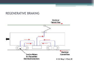
TRACTION MOTOR :
CONTROL AND APPLICATIONS
Content :
• Introduction
• Requirements of a traction system
• Control of DC motors
• Electronic Speed Control Methods for DC Motors
• Pulse Width Modulation
• Braking operation in DC motors
• Conclusion
• References
INTRODUCTION
• Traction motor refers to an electric motor
providing the primary rotational torque of a
machine, usually for conversion into linear
motion (traction).
• Traction motors are used in electrically
powered rail vehicles such as electric multiple
units and electric locomotives
Requirements of an Ideal Traction
System
• High starting pulling effort in order to have rapid
acceleration.
• Equipment capable of withstanding large temporary
overloads for short periods.
• The locomotive should be self contained and able to
run on any route.
• Capability of withstanding voltage fluctuations and
temporary interruption of supply.
• Parallel running usually more than one motor (two or
four motors ) should be possible.
COMPONENTS OF AN A.C LOCOMOTIVE
SEPEX
Short form of SEParate EXcitement of traction
motors where the armature and field coils of an
electric motor are fed with independently controlled
current. This has been made much more useful since
the introduction of thyristor control where motor
control can be much more precise. SEPEX control
also allows a degree of automatic wheel slip control
during acceleration
The DC Traction Motor: How it Drives the
Axle
How a DC motor drives the axle through a pinion and gearwheel
Speed control of dc motor :
• The purpose of a motor speed controller is to
take a signal representing the required speed,
and to drive a motor at that speed.
• Motor speed can be controlled by
controlling-
- Armature voltage (Va)
- Armature current (Ia)
Cont………
• It is obvious that the speed can be controlled by
varying
flux/pole,  (Flux Control)
resistance Ra of armature circuit (Rheostatic Control)
applied voltage V (Voltage Control)
Cont…
• The above methods have some demerits i.e
A large amount of power is wasted in the
controller resistance. Hence, efficiency is
decreased.
It needs expensive arrangement for dissipation of
heat produced in the controller resistance.
It gives speeds below the normal speed.
Electronic Speed Control Methods for DC
Motors :
• compared to the electric and electromechanical
systems of speed control, the electronic methods have
higher accuracy
greater reliability
quick response
higher efficiency
Principle :
• The main principle is control of power by varying the
duty cycle.
• Here the conduction time to the load is controlled.
• Let
 for a time t1, the input voltage appears across the load ie
ON state.
for t2 time the voltage across the load is zero.
The average voltage at output is given by
Va = 1/T  vodt = t1/T Vs = ft1 Vs = kVs
the average load current
Ia = Va/R = KVs/R
where T is the total time period =t1+t2
k = t1/T is the duty cycle
Cont……
• The rms value of output voltage is
V0 = ( i/T  V0
2 dt ) ½ = k Vs
• The output power and is given by
Pi = 1/T  v0idt = 1/T  v0
2/R dt = kVs2/R
• The duty cycle can be varied from 0 to 1 by varying t1, T or f.
Therefore, the output voltage V0 can be varied from 0 to Vs by
controlling k, and the power flow can be controlled.
• As the time t1 changes the width of pulse is varied and this type
of control is called pulse width modulation (PWM) control.
Pulse Width Modulation :
• Pulse width modulation (PWM) is a method for binary
signals generation, which has 2 signal periods (high
and low).
• The width (W) of each pulse varies between 0 and the
period (T).
• The duty cycle (D) of a signal is the ratio of pulse
width to period.
• D=(t1+t2) / T
Pictures of the Waveform :
• The motor is on for
most of the time and
only off a short while,
so the speed is near
maximum
• The switch is on 50%
and off 50%.
• The motor will only
rotate slowly.
Power Supply :
Circuit Description:
• The transformer is a center tap 12-0-12V 500mA and
supply 12v to the circuit.
• The i/p sine wave is rectified by using full wave
rectifier which convert it to one constant polarity.
• A 1000Fcapacitor is used for filtration purpose.
• The three terminal voltage regulators 7812 provides
regulated DC 12 v outputs for the operation of the
circuit.
Circuit Diagram :
(Motor Controller Sections)
Circuit Description :
• The design is based on astable multivibrator IC1a.
• output is low for a period determined by R1 and high
for a period set by R2 and P1.
• When C1 is discharged, the level at the input of IC1a is
below the lower threshold, so that the output of this
stage is high.
• The capacitor is then charged rapidly via D1 and R1,
and reaches the upper threshold in about
◦ t = ln(2)RC
= ln(2).(22k).(100nf)
=1.5 ms
Cont…..
• As output of IC1a goes low, whereupon C1 is
discharged via D2, R2, and P1.
• The discharge time could be set between 0.2ms and
25ms.
• the duty factor of the output signal may be varied
between 5% and 90%.
• The signal is inverted again and then applied to the
input of transistor BC557 through 4k7.
• The transistor Bc557 act as a buffer which transfer
electrical impedance from one circuit to another
circuit i.e. it act as a pre amplifier.
Cont…
• The o/p of Bc557 is given to the power transistor
2N3055 which is used in a circuit as an amplifier,
detector, or switch.
• The diode connected across the motor is for
freewheeling purpose i.e. the diode used to eliminate
flyback, the sudden voltage spike seen across an
inductive load when its supply voltage is suddenly
reduced or removed.
• The resistance of P1(Potentiometer) is at a minimum,
the rotary speed of the motor is at a maximum.
Advantage :
• PWM duty cycle control techniques enable
greater efficiency of the DC motor .
• PWM switching control methods improve speed
control and reduce the power losses in the
system.
• The pulses reach the full supply voltage and will
produce more torque in a motor by being able to
overcome the internal motor resistances more
easily.
Disadvantages :
• The main Disadvantages of PWM circuits are the
added complexity and the possibility of
generating radio frequency interference .
• It can give speed below the full speed, not above.
• It cannot be used for fast controlling of speed.
THYRISTOR CONTROL
Schematic of AC Electric Locomotive Power System with Thyristor Control and
Separately Excited DC Motors
DC Choppers
Thyristor Control Circuit for DC Supply to DC Motors
AC Locomotives with DC Drives
Schematic of AC locomotive with Tap Changer Control of Transformer
Output
Braking in traction motors
• Dynamic Braking: where the motors become
generators and feed the resulting current back.
• It classified into two categories:
1 Plugging
2. Rheostatic Braking
3. Regenerative Braking
• PLUGGING: Generally plugging is applied by
changing the phase sequence of the three phase
induction and synchronous motor
Rheostatic Braking
• The motors become generators and feed the resulting
current into an on-board resistance.
• When the driver calls for brake, the power circuit
connections to the motors are changed from their
power configuration to a brake configuration and the
resistors inserted into the motor circuit. As the
motor generated energy is dispersed in the resistors
and the train speed slows, the resistors are switched
out in steps, just as they are during acceleration.
Regenerative Braking
• the motors become generators and feed the resulting
current back into the supply system
• a train could use its motors to act as generators and that
this would provide some braking effect if a suitable way
could be found to dispose of the energy.
• Trains were designed therefore, which could return
current, generated during braking, to the supply system
for use by other trains.
REGENERATIVE BRAKING
CONCLUSION
• no single motor is ideal for traction purposes. But;
DC Series Motors are most suitable for this work
• Power Electronics have been resorted to in a major
way as in case of thyristor control.
• Different types of braking for the traction system was
studied.
REFERENCES
WEBSITES
• http://www.railway-technical.com
• http://en.wikipedia.org/wiki/Traction_motor
• http://www.engineeringexpert.net/Engineering-Expert-Witness-
Blog/?tag=traction-motor
BOOKS
• Ned Mohan, Tore M. Undeland, Power electronics: converters,
applications, and design , Third Edition , page 377-395
• Singh, K. B. Khanchandani,Power Electronics, Second Edition , pages 846-
890
Any
query
Electric-Traction-Railways.ppt

Electric-Traction-Railways.ppt

  • 1.
    TRACTION MOTOR : CONTROLAND APPLICATIONS
  • 2.
    Content : • Introduction •Requirements of a traction system • Control of DC motors • Electronic Speed Control Methods for DC Motors • Pulse Width Modulation • Braking operation in DC motors • Conclusion • References
  • 3.
    INTRODUCTION • Traction motorrefers to an electric motor providing the primary rotational torque of a machine, usually for conversion into linear motion (traction). • Traction motors are used in electrically powered rail vehicles such as electric multiple units and electric locomotives
  • 4.
    Requirements of anIdeal Traction System • High starting pulling effort in order to have rapid acceleration. • Equipment capable of withstanding large temporary overloads for short periods. • The locomotive should be self contained and able to run on any route. • Capability of withstanding voltage fluctuations and temporary interruption of supply. • Parallel running usually more than one motor (two or four motors ) should be possible.
  • 5.
    COMPONENTS OF ANA.C LOCOMOTIVE
  • 6.
    SEPEX Short form ofSEParate EXcitement of traction motors where the armature and field coils of an electric motor are fed with independently controlled current. This has been made much more useful since the introduction of thyristor control where motor control can be much more precise. SEPEX control also allows a degree of automatic wheel slip control during acceleration
  • 7.
    The DC TractionMotor: How it Drives the Axle How a DC motor drives the axle through a pinion and gearwheel
  • 8.
    Speed control ofdc motor : • The purpose of a motor speed controller is to take a signal representing the required speed, and to drive a motor at that speed. • Motor speed can be controlled by controlling- - Armature voltage (Va) - Armature current (Ia)
  • 9.
    Cont……… • It isobvious that the speed can be controlled by varying flux/pole,  (Flux Control) resistance Ra of armature circuit (Rheostatic Control) applied voltage V (Voltage Control)
  • 10.
    Cont… • The abovemethods have some demerits i.e A large amount of power is wasted in the controller resistance. Hence, efficiency is decreased. It needs expensive arrangement for dissipation of heat produced in the controller resistance. It gives speeds below the normal speed.
  • 11.
    Electronic Speed ControlMethods for DC Motors : • compared to the electric and electromechanical systems of speed control, the electronic methods have higher accuracy greater reliability quick response higher efficiency
  • 12.
    Principle : • Themain principle is control of power by varying the duty cycle. • Here the conduction time to the load is controlled. • Let  for a time t1, the input voltage appears across the load ie ON state. for t2 time the voltage across the load is zero. The average voltage at output is given by Va = 1/T  vodt = t1/T Vs = ft1 Vs = kVs the average load current Ia = Va/R = KVs/R where T is the total time period =t1+t2 k = t1/T is the duty cycle
  • 13.
    Cont…… • The rmsvalue of output voltage is V0 = ( i/T  V0 2 dt ) ½ = k Vs • The output power and is given by Pi = 1/T  v0idt = 1/T  v0 2/R dt = kVs2/R • The duty cycle can be varied from 0 to 1 by varying t1, T or f. Therefore, the output voltage V0 can be varied from 0 to Vs by controlling k, and the power flow can be controlled. • As the time t1 changes the width of pulse is varied and this type of control is called pulse width modulation (PWM) control.
  • 14.
    Pulse Width Modulation: • Pulse width modulation (PWM) is a method for binary signals generation, which has 2 signal periods (high and low). • The width (W) of each pulse varies between 0 and the period (T). • The duty cycle (D) of a signal is the ratio of pulse width to period. • D=(t1+t2) / T
  • 15.
    Pictures of theWaveform : • The motor is on for most of the time and only off a short while, so the speed is near maximum • The switch is on 50% and off 50%. • The motor will only rotate slowly.
  • 16.
  • 17.
    Circuit Description: • Thetransformer is a center tap 12-0-12V 500mA and supply 12v to the circuit. • The i/p sine wave is rectified by using full wave rectifier which convert it to one constant polarity. • A 1000Fcapacitor is used for filtration purpose. • The three terminal voltage regulators 7812 provides regulated DC 12 v outputs for the operation of the circuit.
  • 18.
    Circuit Diagram : (MotorController Sections)
  • 19.
    Circuit Description : •The design is based on astable multivibrator IC1a. • output is low for a period determined by R1 and high for a period set by R2 and P1. • When C1 is discharged, the level at the input of IC1a is below the lower threshold, so that the output of this stage is high. • The capacitor is then charged rapidly via D1 and R1, and reaches the upper threshold in about ◦ t = ln(2)RC = ln(2).(22k).(100nf) =1.5 ms
  • 20.
    Cont….. • As outputof IC1a goes low, whereupon C1 is discharged via D2, R2, and P1. • The discharge time could be set between 0.2ms and 25ms. • the duty factor of the output signal may be varied between 5% and 90%. • The signal is inverted again and then applied to the input of transistor BC557 through 4k7. • The transistor Bc557 act as a buffer which transfer electrical impedance from one circuit to another circuit i.e. it act as a pre amplifier.
  • 21.
    Cont… • The o/pof Bc557 is given to the power transistor 2N3055 which is used in a circuit as an amplifier, detector, or switch. • The diode connected across the motor is for freewheeling purpose i.e. the diode used to eliminate flyback, the sudden voltage spike seen across an inductive load when its supply voltage is suddenly reduced or removed. • The resistance of P1(Potentiometer) is at a minimum, the rotary speed of the motor is at a maximum.
  • 22.
    Advantage : • PWMduty cycle control techniques enable greater efficiency of the DC motor . • PWM switching control methods improve speed control and reduce the power losses in the system. • The pulses reach the full supply voltage and will produce more torque in a motor by being able to overcome the internal motor resistances more easily.
  • 23.
    Disadvantages : • Themain Disadvantages of PWM circuits are the added complexity and the possibility of generating radio frequency interference . • It can give speed below the full speed, not above. • It cannot be used for fast controlling of speed.
  • 24.
    THYRISTOR CONTROL Schematic ofAC Electric Locomotive Power System with Thyristor Control and Separately Excited DC Motors
  • 25.
    DC Choppers Thyristor ControlCircuit for DC Supply to DC Motors
  • 26.
    AC Locomotives withDC Drives Schematic of AC locomotive with Tap Changer Control of Transformer Output
  • 27.
    Braking in tractionmotors • Dynamic Braking: where the motors become generators and feed the resulting current back. • It classified into two categories: 1 Plugging 2. Rheostatic Braking 3. Regenerative Braking • PLUGGING: Generally plugging is applied by changing the phase sequence of the three phase induction and synchronous motor
  • 28.
    Rheostatic Braking • Themotors become generators and feed the resulting current into an on-board resistance. • When the driver calls for brake, the power circuit connections to the motors are changed from their power configuration to a brake configuration and the resistors inserted into the motor circuit. As the motor generated energy is dispersed in the resistors and the train speed slows, the resistors are switched out in steps, just as they are during acceleration.
  • 29.
    Regenerative Braking • themotors become generators and feed the resulting current back into the supply system • a train could use its motors to act as generators and that this would provide some braking effect if a suitable way could be found to dispose of the energy. • Trains were designed therefore, which could return current, generated during braking, to the supply system for use by other trains.
  • 30.
  • 31.
    CONCLUSION • no singlemotor is ideal for traction purposes. But; DC Series Motors are most suitable for this work • Power Electronics have been resorted to in a major way as in case of thyristor control. • Different types of braking for the traction system was studied.
  • 32.
    REFERENCES WEBSITES • http://www.railway-technical.com • http://en.wikipedia.org/wiki/Traction_motor •http://www.engineeringexpert.net/Engineering-Expert-Witness- Blog/?tag=traction-motor BOOKS • Ned Mohan, Tore M. Undeland, Power electronics: converters, applications, and design , Third Edition , page 377-395 • Singh, K. B. Khanchandani,Power Electronics, Second Edition , pages 846- 890
  • 33.