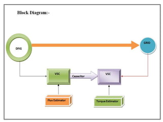
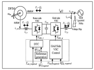
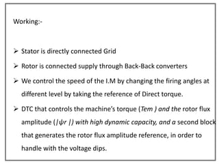
Direct Torque Control for Doubly Fed Induction
        Machine-Based Wind Turbines

  Under Voltage Dips and Without Crowbar
                 Protection
Abstract:-
       This paper proposes a rotor flux amplitude reference generation
  strategy for doubly fed induction machine based wind turbines.

       It is specially designed to address perturbations, such as voltage
  dips, keeping controlled the torque of the wind turbine, and
  considerably reducing the stator and rotor over currents during faults.
       In addition, a direct torque control strategy that provides fast
  dynamic response accompanies the overall control of the wind turbine.
       Despite the fact that the proposed control does not totally
  eliminate the necessity of the typical crowbar protection for this kind of
  turbines, it eliminates the activation of this protection during low depth
  voltage dips.
Aim:-

 The main aim of the project is to analyze the performance of the

  double fed induction generator(DFIG) which is an integral part of the
  wind energy generation system under unbalanced grid fault condition. .
  And we have to control the speed of the induction generator to
  produce constant current even in voltage dips and un balanced load
  conditions by using a new method         Direct torque control method
  with out using crowbar protections.
INTRODUCTION

 Here we discuss about the analysis on the control of doubly fed
  induction machine (DFIM) based high-power wind turbines when they
  operate under presence of voltage dips.

 Most of the wind turbine manufacturers build this kind of wind turbines
  with a back-to-back converter sized to approximately 30% of the
  nominal power.

 This reduced converter design provokes that when the machine is
  affected by voltage dips, it needs a special crowbar protection in order
  to avoid damages in the wind turbine and meet the grid-code
  requirements.
 The main objective of the control strategy proposed in this project is to
  eliminate the necessity of the crowbar protection when low-depth
  voltage dips occurs.

 Hence, by using direct torque control (DTC), with a proper rotor flux
  generation strategy, during the fault it will be possible to maintain the
  machine connected to the grid, generating power from the
  wind, reducing over currents, and eliminating the torque oscillations
  that normally produce such voltage dips
Conventional Methods:-

       Sensor methods
       Power electronic converters (VSI)
       Sensor less methods (Adaptive observer method)
       Crowbar protection
Disadvantages:-

       • Increases the size of the machine

       • Noise pollution

       • Drift effects are increased

   – By using A.O techniques

       • Require more memory space,

       • Have to check for number of estimated values,

       • Difficult to tune with number of values,

       • More complex of calculating part.
Proposed method:-

• Direct torque control method is one of the best control strategies which
   allow a torque control in steady state and transient operation of
   induction motor.

• The main aim of direct torque control strategies is to effectively control
   the torque and flux of induction motor.

• Direct torque control method made the motor more accurate and fast
   torque control, high dynamic speed response and simple to control.
Advantages:-

   – No need to use sensors.

   – Efficient output.

   – No chance of drift effects and power losses.

   – No need to use a crowbar protection.

   – Reduce the stator and rotor over currents during faults.
Wind Generation
• When wind strikes the stationary blade of the
  wind turbine forcely then it starts rotating.
 This blades are connected to hub it is
 connected to low speed shaft.
 This shaft starts rotate with the speed of wind and give
  dynamic energy to Gear box.

 This gear box connected to Generator with high speed level
  shaft to give more dynamic energy to the Generator

 This Generator converts this Gearbox M.E into E.E.

 This is the general process to generate electricity through

  Wind energy.
Why we use DFIG?
• Generally in wind generation we use DFIG.

• The reason is the speed of the rotor is based upon the wind speed.

• Wind speed is varies at every time. Due to this variation of speed the
   rotor shaft will be damaged.

• To overcome this problem in wind generation we use a specially
   designed machine “Double fed induction generator”

• It can withstand under presence of voltage dips,

• Ability to control rotor currents.

• Allows for reactive power control and variable speed operation.
Methods of Speed Control of Induction motors


(1) Stator voltage Control

(2) Stator Frequency Control

(3) Stator Current Control

(4) V/F Control

(5) Slip power recovery Control ( Wound Rotor Induction Machine)


                                                                   15
• General control techniques to control the speed of the Induction
  Motor are


   – Stator side

   – Rotor side
• But it is difficult to control through Rotor side and Stator side.
  The next step is to control the I.M is by using Sensors.
Disadvantages of sensors:-
If we use sensors to control IM,

   I.      We have to put voltage and current sensors at both stator and rotor

           sides.

   II.     So It increases the size of the machine and

   III.    It increases the cost of the machine.

   IV. If we use sensors in get some noisy, and sound polluted.

   V.      Drift effects are increased.

           To over come this problems the next step to control the I.M we go for

        sensor less techniques.
By using this AO Techniques we get accuracy output, but the
  main disadvantages are


   a)   Require more memory space,

   b)   Have to check for number of estimated values,

   c)   Difficult to tune with number of values,

   d)   More complex of calculating part.


To overcome this problems we use Crow-Bar protection.
Crowbar protection.
• It is used to mitigate the high voltages and high current
  ratings.

• A crowbar thyristor is connected across the input dc
  terminals.

• A current sensing resistor detects the value of converter
  current. If it exceeds preset value, gate circuit provides the
  signal to crowbar SCR and turns it on in a few microseconds.
• If we use Crow-Bar protection if any fault occurs
   – we have to replace the fuse and Thyristor.
   – The circuit became complex to design
   – The size and cost of the equipment increased.
   – Externally we have to add another device to reduce voltage
      dips.


   In order to overcome these problems and to reduce the faults
      with in the transmission here we use a new method
    Direct Torque Control Method.
Principles of Vector Control
 The basic conceptual implementation of vector control is
  illustrated in the below block diagram:


Note: The inverter is omitted from this diagram.
The motor phase currents, ia, ib and ic are converted to idss and
 iqss   in the stationary reference frame. These are then
 converted to the synchronously rotating reference frame d-q
 currents, ids and iqs.


In the controller two inverse transforms are performed:

 1) From the synchronous d-q to the

    stationary d-q reference frame;

 2) From d*-q* to a*, b*, c*.
There are two approaches to vector control:


1) Direct field oriented current control

 - here the rotation angle of the iqse vector with respect to the
  stator flux         s
                  qr ’    is being directly determined (e.g. by measuring
  air gap flux)


2) Indirect field oriented current control

 - here the rotor angle is being measured indirectly, such as by
  measuring slip speed.
Direct Vector Control
In direct vector control the field angle is calculated by using
 terminal voltages and current or Hall sensors or flux sense
 windings.


A block diagram of a direct vector control method using a PWM
 voltage-fed inverter is shown on the next slide.
Direct Vector Control (cont’d)
The principal vector control parameters, ids* and iqs*, which
are dc values in the synchronously rotating reference frame, are
converted to the stationary reference frame (using the vector
rotation (VR) block) by using the unit vector cos       e   and sin e.
These stationary reference frame control parameters idss* and
iqss* are then changed to the phase current command
signals, ia*, ib*, and ic* which are fed to the PWM inverter.
A flux control loop is used to precisely control the flux. Torque
 control is achieved through the current iqs* which is generated
 from the speed control loop (which includes a bipolar limiter
 that is not shown). The torque can be negative which will
 result in a negative phase orientation for iqs in the phasor
 diagram.


How do we maintain idsand iqs orthogonality? This is explained
 in the next slide.
Why FOC ?

• IM is superior to DC machine with respect to
   size, weight, inertia, cost, speed


• DC motor is superior to IM with respect to ease of control

   – High performance with simple control due de-coupling
      component of torque and flux

• FOC transforms the dynamics of IM to become similar to the
  DC motor’s – decoupling the torque and flux components
Basic Principles DC machine
                   By keeping flux
                   constant, torque can be
                   controlled by controlling
                   armature current

                     a

                             Te = k If Ia


                Current in
                Current out
       f
Basic Principles of IM
     s
         a
                         Stator current produce stator
                     r   flux

c’               b’
                         Stator flux induces rotor
                         current produces rotor flux


                         Interaction between stator and
                         rotor fluxes produces torque
b
                 c

                         Space angle between stator
                         and rotor fluxes varies with
                         load, and speed
FOC of IM drive
Torque equation :

                           3 p
                     Te              s
                                              is
                           2 2

                          3 p Lm
                     Te                   r        is
                          2 2 Lr
In d-q axis :
                      3 p Lm
                Te               (       rd
                                              i sq      rq
                                                             i sd )
                      2 2 Lr
FOC of IM drive
In d-q axis :
                              3 p Lm
                     Te                (   rd
                                                i sq          rq
                                                                   i sd )
                              2 2 Lr


Choose a frame such that:

                 r
            rd            r                      rq
                                                      r
                                                          0
FOC of IM drive


Choose a frame such that:

                 r
            rd       r           rq
                                      r
                                          0
FOC of IM drive
Choose a frame such that:

                       r
                  rd           r                         rq
                                                              r
                                                                         0

                                                    qs
As seen by stator reference frame:

     3 p Lm                                                              is
Te            (   rd
                       i sq   rq
                                   i sd )   i sq
     2 2 Lr
                                                                                   r
                                               rq


                                                                  i sd                 ds
                                                                              rd
FOC of IM drive
     Choose a frame such that:

                            r
                       rd         r                        rq
                                                                r
                                                                    0

                                                      qs
     Rotating reference frame:             r
                                      q
                                                                    is

                                                                                    d    r
        3 p Lm
Te               (     i ir
                     r rdsq sq   rq
                                      i sd )                                    r

        2 2 Lr                                    r
                                               i sq                         r
                                                                         i sd


                                                                                        ds
FOC of IM drive
 To implement rotor flux FOC need to know rotor flux position:

       (i)                Indirect FOC
Synchronous speed obtain by adding slip speed and rotor speed

Rotor voltage equation:                                                                         Rotor flux equation:
                          g
         g       d        r                               g
                                                                                                        g
                                                                                                            L r ir
                                                                                                                  g
                                                                                                                            L m is
                                                                                                                                    g
0    R i
       r r
                                  j(       g       r
                                                     )    r
                                                                                                        r
                     dt

                                                                                           g
                                       Rr      g         L mR r             g    d         r                         g
                              0                r
                                                                        i   s
                                                                                               j(   g       r
                                                                                                              )      r
                                       Lr                 Lr                         dt


                          Rr                   L mR r                                          d        r
             0                         r
                                                              i   sd
                                                                    r
                                                                                ji   sq
                                                                                       r
                                                                                                             j(      slip
                                                                                                                            )   r
                          Lr                       Lr                                           dt
FOC of IM drive - indirect


                      d component                                                  q component


    Rr           L mR r             d        r                                L mR r
0            r
                           i sdr                                      0                  i sqr      (   slip   )   r
    Lr            Lr                    dt                                         Lr


                 Rr            L mR r                                     d    r
         0             r
                                                 i   sd
                                                       r
                                                           ji   sq
                                                                  r
                                                                                        j(   slip
                                                                                                    )    r
                 Lr                Lr                                     dt
FOC of IM drive - indirect

                     Rr                L mR r                                              d       r
         0                 r
                                                         i   sd
                                                               r
                                                                        ji      sq
                                                                                  r
                                                                                                              j(    slip
                                                                                                                           )    r
                     Lr                    Lr                                              dt


                          d component                                                                  q component
                                                                        *
                                                                   4 Te         Lr
                                                         i sqr *
                                                                   3p       r
                                                                                Lm


    Rr               L mR r                 d        r                                         L mR r
0            r
                                   i sdr                                              0                         i sqr      (   slip   )   r
    Lr                Lr                        dt                                                     Lr


                               *                                                           L mR r
                               r                                            (          )                    i sqr
         i sd *  r                                                                slip         *
                                                                                               r
                                                                                                   Lr
                          Lm
FOC of IM drive - indirect
T*                               *
                                 r
                                              i   r *
                                                   sq             isq*          ia*
          i sdr *
                         Lm

                    4 Te
                             *
                                     Lr                                  2/3    ib*   CC
     i sqr *
                                              i   r *   ej
                    3p           r
                                     Lm            sd             isd*          ic*   VSI
*
                    L mR r
     (   slip
                )        *
                                      i sqr
                         r
                             Lr


                                                        1/s

                                     slip                                r
                                                    +         +


           Rotating frame                                    Stationary frame
FOC of IM drive
(ii)                 Direct FOC

Rotor flux estimated from motor’s terminal variables

Rotor flux can be estimated by:

            Rr       LmR r            d        r            g
       0         r
                             is                     j   r   r
            Lr        Lr                  dt


                                                                      Express in stationary frame

           3 p Lm
Te                                r
                                               is
           2 2 Lr
FOC of IM drive
     (ii)            Direct FOC

     Rr             L mR r                d      r                 g
0              r
                                   is                     j    r   r
     Lr                  Lr                 dt


     Rr                                 L mR r                            d(   rd
                                                                                         j   rq
                                                                                                  )
0         (    rd
                     j    rq
                               )                 ( i sd        ji sq )i                                j        r
                                                                                                                    (    rd
                                                                                                                                 j      rq
                                                                                                                                             )
     Lr                                  Lr                                         dt

                                                 d                                           q

              Rr              L mR r                                                             Rr                     L mR r
                                          i sd                     dt          rq                          rq
                                                                                                                                 i sq            r   rd
                                                                                                                                                          dt
rd
              Lr
                    rd
                                   Lr
                                                      r       rq
                                                                                                 Lr                      Lr


                                                     rq
                                                                                                      2                 2
                                                                                         r            rd                rq
                                                     rd
FOC of IM drive - direct
T*                               i    r *
                                       sq                           isq*              ia*
                       TC
                                                                           2/3        ib*          CC
                                                        ej
r*                                                                 isd*                            VSI
                                 i    r *

                       FC
                                       sd
                                                                                      ic*

     r
             Te
              Rr        LmR r          d        r           g
         0         r
                                 is                 j   r   r
              Lr            Lr             dt


                                                                                      3 p Lm
                                                                                 Te            r
                                                                                                   is
                                                                                      2 2 Lr


              Rotating frame                                    Stationary frame
Working:-


 Stator is directly connected Grid

 Rotor is connected supply through Back-Back converters

 We control the speed of the I.M by changing the firing angles at
  different level by taking the reference of Direct torque.

 DTC that controls the machine’s torque (Tem ) and the rotor flux
  amplitude (|ψr |) with high dynamic capacity, and a second block
  that generates the rotor flux amplitude reference, in order to
  handle with the voltage dips.
What is MATLAB?

 MATLAB (Matrix Laboratory)
– MATLAB is developed by The Math Works, Inc.
– MATLAB is a high-level technical computing
  language and interactive environment for
  algorithm development, data visualization, data
  analysis, and numeric computation.
– MATLAB can be install on Unix, Windows
• About MATLAB/Simulink:
  – Matlab is a high-performance language for technical
    computing.

  – It integrates computation, visualization, and programming in an
    easy-to-use environment where problems and solutions are
    expressed in familiar mathematical notation.
History of MATLAB:

     Fortran subroutines for solving linear (LINPACK) and eigen value
    (EISPACK) problems
     Developed primarily by Cleve Moler in the 1970’s

     Later, when teaching courses in mathematics,       Moler wanted    his
    students to be able to use LINPACK and EISPACK without requiring
    knowledge of Fortran
     MATLAB developed as an interactive system to access LINPACK and
    EISPACK.
     MATLAB gained popularity primarily through word of mouth because it
    was not officially distributed.
     In the 1980’s, MATLAB was rewritten in C with more functionality (such
    as plotting routines)
 The Mathworks, Inc. was created in 1984

 The Mathworks is now responsible for development, sale, and
  support for MATLAB

 The Mathworks is located in Natick,

 The Mathworks is an employer that hires co-ops through our co-op
  program
Strengths of MATLAB
• MATLAB is relatively easy to learn.
• MATLAB code is optimized to be relatively quick
  when performing matrix operations.
• MATLAB may behave like a calculator or as a
  programming language.
• MATLAB is interpreted, errors are easier to fix.
• Although primarily procedural, MATLAB does have
  some object-oriented elements.
Other Features
• 2-D and 3-D graphics functions for visualizing data

• Tools for building custom graphical user interfaces

• Functions for integrating MATLAB based algorithms
  with external applications and languages, such as
  C, C++, Fortran, Java, COM, and Microsoft Excel
Weaknesses of MATLAB
• MATLAB is NOT a general purpose programming
  language.
• MATLAB is an interpreted language (making it for
  the most part slower than a compiled language
  such as C++).
• MATLAB is designed for scientific computation and
  is not suitable for some things (such as parsing
  text).
Components of MATLAB Interface
•   Workspace
•   Current Directory
•   Command History
•   Command Window
SIMULINK
 It is a commercial tool for modeling, simulating and
  analyzing multidomain dynamic systems.
 Its primary interface is a graphical block diagramming
  tool and a customizable set of block libraries.
 Simulink is widely used in control theory and digital
  signal   processing   for   multidomain     simulation
  and Model-based design.
• Generally there are three ways to open Simulink

1.By using start in Matlab

2.By typing Simulink in Command prompt.

3.By clicking Simulink icon in toolbar.
Cont……


Simulink is widely used in control
 theory and digital signal processing for
 multidomain simulation and Model-based
 design.
Simulation diagram
Simulation results
Simulation results
• Conclusion:-

 we control the speed of the induction generator to produce
  constant current even in voltage dips and un balanced load
  conditions with out using any crowbar protections and by using
  a new method        Direct torque control method.

Direct torque control method

  • 1.
    Direct Torque Controlfor Doubly Fed Induction Machine-Based Wind Turbines Under Voltage Dips and Without Crowbar Protection
  • 2.
    Abstract:- This paper proposes a rotor flux amplitude reference generation strategy for doubly fed induction machine based wind turbines. It is specially designed to address perturbations, such as voltage dips, keeping controlled the torque of the wind turbine, and considerably reducing the stator and rotor over currents during faults. In addition, a direct torque control strategy that provides fast dynamic response accompanies the overall control of the wind turbine. Despite the fact that the proposed control does not totally eliminate the necessity of the typical crowbar protection for this kind of turbines, it eliminates the activation of this protection during low depth voltage dips.
  • 3.
    Aim:-  The mainaim of the project is to analyze the performance of the double fed induction generator(DFIG) which is an integral part of the wind energy generation system under unbalanced grid fault condition. . And we have to control the speed of the induction generator to produce constant current even in voltage dips and un balanced load conditions by using a new method Direct torque control method with out using crowbar protections.
  • 4.
    INTRODUCTION  Here wediscuss about the analysis on the control of doubly fed induction machine (DFIM) based high-power wind turbines when they operate under presence of voltage dips.  Most of the wind turbine manufacturers build this kind of wind turbines with a back-to-back converter sized to approximately 30% of the nominal power.  This reduced converter design provokes that when the machine is affected by voltage dips, it needs a special crowbar protection in order to avoid damages in the wind turbine and meet the grid-code requirements.
  • 5.
     The mainobjective of the control strategy proposed in this project is to eliminate the necessity of the crowbar protection when low-depth voltage dips occurs.  Hence, by using direct torque control (DTC), with a proper rotor flux generation strategy, during the fault it will be possible to maintain the machine connected to the grid, generating power from the wind, reducing over currents, and eliminating the torque oscillations that normally produce such voltage dips
  • 6.
    Conventional Methods:- Sensor methods Power electronic converters (VSI) Sensor less methods (Adaptive observer method) Crowbar protection
  • 7.
    Disadvantages:- • Increases the size of the machine • Noise pollution • Drift effects are increased – By using A.O techniques • Require more memory space, • Have to check for number of estimated values, • Difficult to tune with number of values, • More complex of calculating part.
  • 8.
    Proposed method:- • Directtorque control method is one of the best control strategies which allow a torque control in steady state and transient operation of induction motor. • The main aim of direct torque control strategies is to effectively control the torque and flux of induction motor. • Direct torque control method made the motor more accurate and fast torque control, high dynamic speed response and simple to control.
  • 10.
    Advantages:- – No need to use sensors. – Efficient output. – No chance of drift effects and power losses. – No need to use a crowbar protection. – Reduce the stator and rotor over currents during faults.
  • 11.
    Wind Generation • Whenwind strikes the stationary blade of the wind turbine forcely then it starts rotating.
  • 12.
     This bladesare connected to hub it is connected to low speed shaft.
  • 13.
     This shaftstarts rotate with the speed of wind and give dynamic energy to Gear box.  This gear box connected to Generator with high speed level shaft to give more dynamic energy to the Generator  This Generator converts this Gearbox M.E into E.E.  This is the general process to generate electricity through Wind energy.
  • 14.
    Why we useDFIG? • Generally in wind generation we use DFIG. • The reason is the speed of the rotor is based upon the wind speed. • Wind speed is varies at every time. Due to this variation of speed the rotor shaft will be damaged. • To overcome this problem in wind generation we use a specially designed machine “Double fed induction generator” • It can withstand under presence of voltage dips, • Ability to control rotor currents. • Allows for reactive power control and variable speed operation.
  • 15.
    Methods of SpeedControl of Induction motors (1) Stator voltage Control (2) Stator Frequency Control (3) Stator Current Control (4) V/F Control (5) Slip power recovery Control ( Wound Rotor Induction Machine) 15
  • 16.
    • General controltechniques to control the speed of the Induction Motor are – Stator side – Rotor side
  • 18.
    • But itis difficult to control through Rotor side and Stator side. The next step is to control the I.M is by using Sensors.
  • 19.
    Disadvantages of sensors:- Ifwe use sensors to control IM, I. We have to put voltage and current sensors at both stator and rotor sides. II. So It increases the size of the machine and III. It increases the cost of the machine. IV. If we use sensors in get some noisy, and sound polluted. V. Drift effects are increased. To over come this problems the next step to control the I.M we go for sensor less techniques.
  • 21.
    By using thisAO Techniques we get accuracy output, but the main disadvantages are a) Require more memory space, b) Have to check for number of estimated values, c) Difficult to tune with number of values, d) More complex of calculating part. To overcome this problems we use Crow-Bar protection.
  • 22.
    Crowbar protection. • Itis used to mitigate the high voltages and high current ratings. • A crowbar thyristor is connected across the input dc terminals. • A current sensing resistor detects the value of converter current. If it exceeds preset value, gate circuit provides the signal to crowbar SCR and turns it on in a few microseconds.
  • 24.
    • If weuse Crow-Bar protection if any fault occurs – we have to replace the fuse and Thyristor. – The circuit became complex to design – The size and cost of the equipment increased. – Externally we have to add another device to reduce voltage dips. In order to overcome these problems and to reduce the faults with in the transmission here we use a new method Direct Torque Control Method.
  • 25.
    Principles of VectorControl The basic conceptual implementation of vector control is illustrated in the below block diagram: Note: The inverter is omitted from this diagram.
  • 26.
    The motor phasecurrents, ia, ib and ic are converted to idss and iqss in the stationary reference frame. These are then converted to the synchronously rotating reference frame d-q currents, ids and iqs. In the controller two inverse transforms are performed: 1) From the synchronous d-q to the stationary d-q reference frame; 2) From d*-q* to a*, b*, c*.
  • 27.
    There are twoapproaches to vector control: 1) Direct field oriented current control - here the rotation angle of the iqse vector with respect to the stator flux s qr ’ is being directly determined (e.g. by measuring air gap flux) 2) Indirect field oriented current control - here the rotor angle is being measured indirectly, such as by measuring slip speed.
  • 28.
    Direct Vector Control Indirect vector control the field angle is calculated by using terminal voltages and current or Hall sensors or flux sense windings. A block diagram of a direct vector control method using a PWM voltage-fed inverter is shown on the next slide.
  • 29.
  • 30.
    The principal vectorcontrol parameters, ids* and iqs*, which are dc values in the synchronously rotating reference frame, are converted to the stationary reference frame (using the vector rotation (VR) block) by using the unit vector cos e and sin e. These stationary reference frame control parameters idss* and iqss* are then changed to the phase current command signals, ia*, ib*, and ic* which are fed to the PWM inverter.
  • 31.
    A flux controlloop is used to precisely control the flux. Torque control is achieved through the current iqs* which is generated from the speed control loop (which includes a bipolar limiter that is not shown). The torque can be negative which will result in a negative phase orientation for iqs in the phasor diagram. How do we maintain idsand iqs orthogonality? This is explained in the next slide.
  • 32.
    Why FOC ? •IM is superior to DC machine with respect to size, weight, inertia, cost, speed • DC motor is superior to IM with respect to ease of control – High performance with simple control due de-coupling component of torque and flux • FOC transforms the dynamics of IM to become similar to the DC motor’s – decoupling the torque and flux components
  • 33.
    Basic Principles DCmachine By keeping flux constant, torque can be controlled by controlling armature current a Te = k If Ia Current in Current out f
  • 34.
    Basic Principles ofIM s a Stator current produce stator r flux c’ b’ Stator flux induces rotor current produces rotor flux Interaction between stator and rotor fluxes produces torque b c Space angle between stator and rotor fluxes varies with load, and speed
  • 35.
    FOC of IMdrive Torque equation : 3 p Te s is 2 2 3 p Lm Te r is 2 2 Lr In d-q axis : 3 p Lm Te ( rd i sq rq i sd ) 2 2 Lr
  • 36.
    FOC of IMdrive In d-q axis : 3 p Lm Te ( rd i sq rq i sd ) 2 2 Lr Choose a frame such that: r rd r rq r 0
  • 37.
    FOC of IMdrive Choose a frame such that: r rd r rq r 0
  • 38.
    FOC of IMdrive Choose a frame such that: r rd r rq r 0 qs As seen by stator reference frame: 3 p Lm is Te ( rd i sq rq i sd ) i sq 2 2 Lr r rq i sd ds rd
  • 39.
    FOC of IMdrive Choose a frame such that: r rd r rq r 0 qs Rotating reference frame: r q is d r 3 p Lm Te ( i ir r rdsq sq rq i sd ) r 2 2 Lr r i sq r i sd ds
  • 40.
    FOC of IMdrive To implement rotor flux FOC need to know rotor flux position: (i) Indirect FOC Synchronous speed obtain by adding slip speed and rotor speed Rotor voltage equation: Rotor flux equation: g g d r g g L r ir g L m is g 0 R i r r j( g r ) r r dt g Rr g L mR r g d r g 0 r i s j( g r ) r Lr Lr dt Rr L mR r d r 0 r i sd r ji sq r j( slip ) r Lr Lr dt
  • 41.
    FOC of IMdrive - indirect d component q component Rr L mR r d r L mR r 0 r i sdr 0 i sqr ( slip ) r Lr Lr dt Lr Rr L mR r d r 0 r i sd r ji sq r j( slip ) r Lr Lr dt
  • 42.
    FOC of IMdrive - indirect Rr L mR r d r 0 r i sd r ji sq r j( slip ) r Lr Lr dt d component q component * 4 Te Lr i sqr * 3p r Lm Rr L mR r d r L mR r 0 r i sdr 0 i sqr ( slip ) r Lr Lr dt Lr * L mR r r ( ) i sqr i sd * r slip * r Lr Lm
  • 43.
    FOC of IMdrive - indirect T* * r i r * sq isq* ia* i sdr * Lm 4 Te * Lr 2/3 ib* CC i sqr * i r * ej 3p r Lm sd isd* ic* VSI * L mR r ( slip ) * i sqr r Lr 1/s slip r + + Rotating frame Stationary frame
  • 44.
    FOC of IMdrive (ii) Direct FOC Rotor flux estimated from motor’s terminal variables Rotor flux can be estimated by: Rr LmR r d r g 0 r is j r r Lr Lr dt Express in stationary frame 3 p Lm Te r is 2 2 Lr
  • 45.
    FOC of IMdrive (ii) Direct FOC Rr L mR r d r g 0 r is j r r Lr Lr dt Rr L mR r d( rd j rq ) 0 ( rd j rq ) ( i sd ji sq )i j r ( rd j rq ) Lr Lr dt d q Rr L mR r Rr L mR r i sd dt rq rq i sq r rd dt rd Lr rd Lr r rq Lr Lr rq 2 2 r rd rq rd
  • 46.
    FOC of IMdrive - direct T* i r * sq isq* ia* TC 2/3 ib* CC ej r* isd* VSI i r * FC sd ic* r Te Rr LmR r d r g 0 r is j r r Lr Lr dt 3 p Lm Te r is 2 2 Lr Rotating frame Stationary frame
  • 48.
    Working:-  Stator isdirectly connected Grid  Rotor is connected supply through Back-Back converters  We control the speed of the I.M by changing the firing angles at different level by taking the reference of Direct torque.  DTC that controls the machine’s torque (Tem ) and the rotor flux amplitude (|ψr |) with high dynamic capacity, and a second block that generates the rotor flux amplitude reference, in order to handle with the voltage dips.
  • 49.
    What is MATLAB? MATLAB (Matrix Laboratory) – MATLAB is developed by The Math Works, Inc. – MATLAB is a high-level technical computing language and interactive environment for algorithm development, data visualization, data analysis, and numeric computation. – MATLAB can be install on Unix, Windows
  • 50.
    • About MATLAB/Simulink: – Matlab is a high-performance language for technical computing. – It integrates computation, visualization, and programming in an easy-to-use environment where problems and solutions are expressed in familiar mathematical notation.
  • 51.
    History of MATLAB:  Fortran subroutines for solving linear (LINPACK) and eigen value (EISPACK) problems  Developed primarily by Cleve Moler in the 1970’s  Later, when teaching courses in mathematics, Moler wanted his students to be able to use LINPACK and EISPACK without requiring knowledge of Fortran  MATLAB developed as an interactive system to access LINPACK and EISPACK.  MATLAB gained popularity primarily through word of mouth because it was not officially distributed.  In the 1980’s, MATLAB was rewritten in C with more functionality (such as plotting routines)
  • 52.
     The Mathworks,Inc. was created in 1984  The Mathworks is now responsible for development, sale, and support for MATLAB  The Mathworks is located in Natick,  The Mathworks is an employer that hires co-ops through our co-op program
  • 53.
    Strengths of MATLAB •MATLAB is relatively easy to learn. • MATLAB code is optimized to be relatively quick when performing matrix operations. • MATLAB may behave like a calculator or as a programming language. • MATLAB is interpreted, errors are easier to fix. • Although primarily procedural, MATLAB does have some object-oriented elements.
  • 54.
    Other Features • 2-Dand 3-D graphics functions for visualizing data • Tools for building custom graphical user interfaces • Functions for integrating MATLAB based algorithms with external applications and languages, such as C, C++, Fortran, Java, COM, and Microsoft Excel
  • 55.
    Weaknesses of MATLAB •MATLAB is NOT a general purpose programming language. • MATLAB is an interpreted language (making it for the most part slower than a compiled language such as C++). • MATLAB is designed for scientific computation and is not suitable for some things (such as parsing text).
  • 56.
    Components of MATLABInterface • Workspace • Current Directory • Command History • Command Window
  • 58.
    SIMULINK  It isa commercial tool for modeling, simulating and analyzing multidomain dynamic systems.  Its primary interface is a graphical block diagramming tool and a customizable set of block libraries.  Simulink is widely used in control theory and digital signal processing for multidomain simulation and Model-based design.
  • 59.
    • Generally thereare three ways to open Simulink 1.By using start in Matlab 2.By typing Simulink in Command prompt. 3.By clicking Simulink icon in toolbar.
  • 60.
    Cont…… Simulink is widelyused in control theory and digital signal processing for multidomain simulation and Model-based design.
  • 70.
  • 71.
  • 72.
  • 73.
    • Conclusion:- wecontrol the speed of the induction generator to produce constant current even in voltage dips and un balanced load conditions with out using any crowbar protections and by using a new method Direct torque control method.